
RFEM/RSTAB BIM link for steel member design (EN) - OLD
1 How to activate the link
- Install the latest version of IDEA StatiCa
- Make sure you are using a supported version of RFEM/RSTAB
- You need to have the COM module installed in RFEM/RSTAB to create the BIM link with IDEA StatiCa.
IDEA StatiCa automatically integrates the BIM link into your CAD/CAE software during its installation. You can check the status and activate more BIM links for other software installed later in the BIM link installer.
Open IDEA StatiCa and navigate to the panel BIM and open the BIM link installer. A notification "Run as administrator" may appear, please confirm with the Yes button.
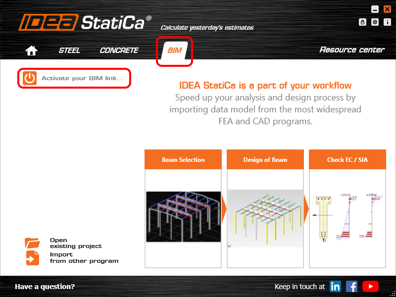
Select the software to integrate the IDEA StatiCa BIM link, click the Install button and check the status.

Note: RFEM/RSTAB BIM link provides importing only under the Eurocode (EN) standard.
2 How to use the link
First, open the source file RFEM.rf5 from the provided files for download (at the bottom of this tutorial) and open it in RFEM/RSTAB. There navigate to menu Add-on Modules then External Modules and run IDEA Statica Steel (for RFEM6/RSTAB9 use this process).

The Code-check manager opens and you can start the import process. Select one beam or column in the RFEM/RSTAB model and click Member to import it for the analysis in IDEA StatiCa Member under the EN code.

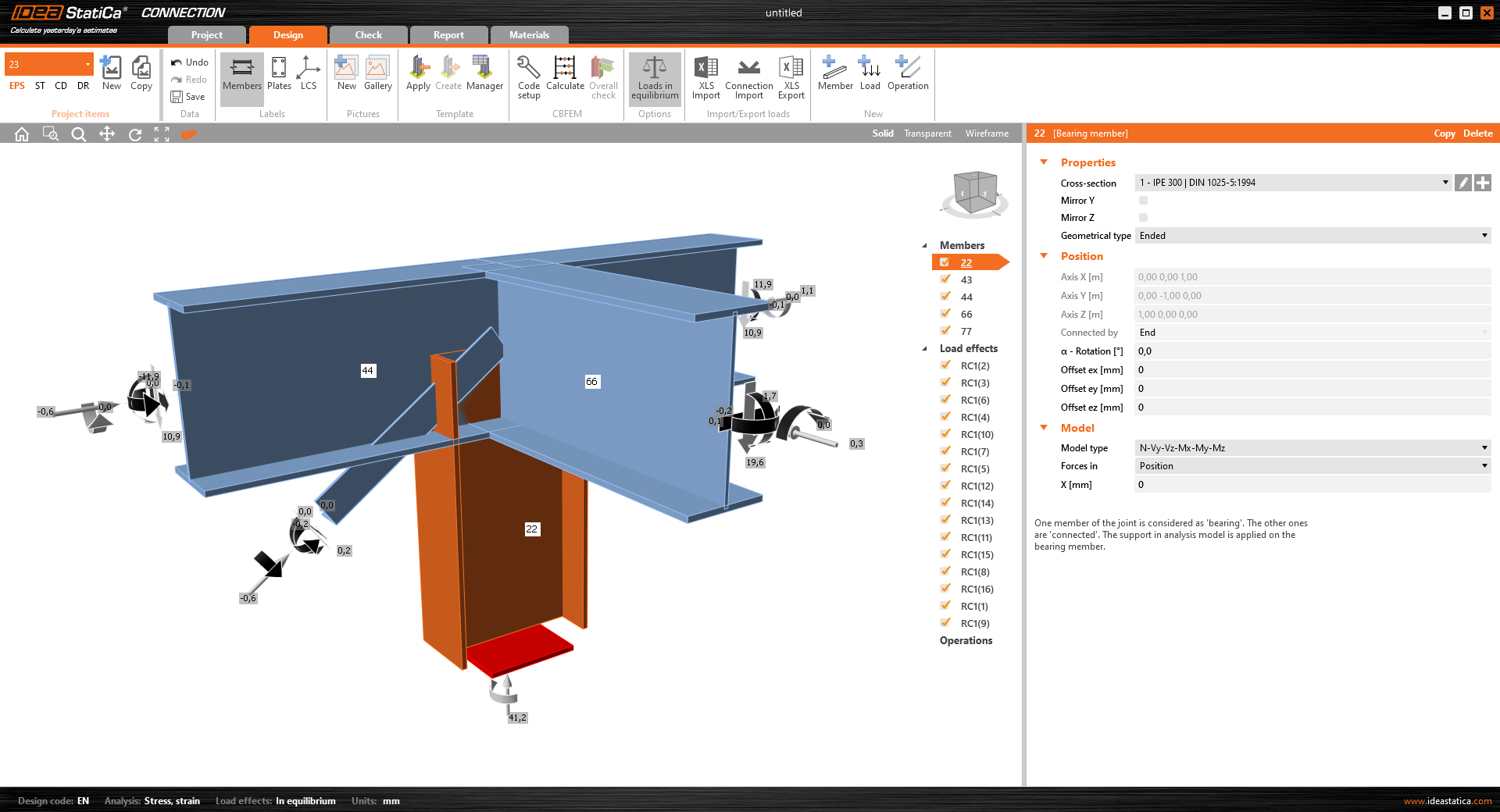
The member is added to the list together with corresponding joints and by selecting it the wireframe model together with the tab of cross-sections is displayed. In this step, you can manage the imported load cases. Leave the default settings and start configuring the connections first.

3 Design
Select node 22 in the list, click Finish, and open it in the Connection module to configure the connections by following the tutorial BIM link tutorial Connection - RFEM/RSTAB (EN) from chapter 3 on.

After that, select node 23, again click Finish, and open it to design the connections.

Instead of designing all the connections of this joint by adding the operations, take advantage of the predefined template from the provided files for download in this tutorial.
Open the template Manager and import the template into your IDEA StatiCa template database.
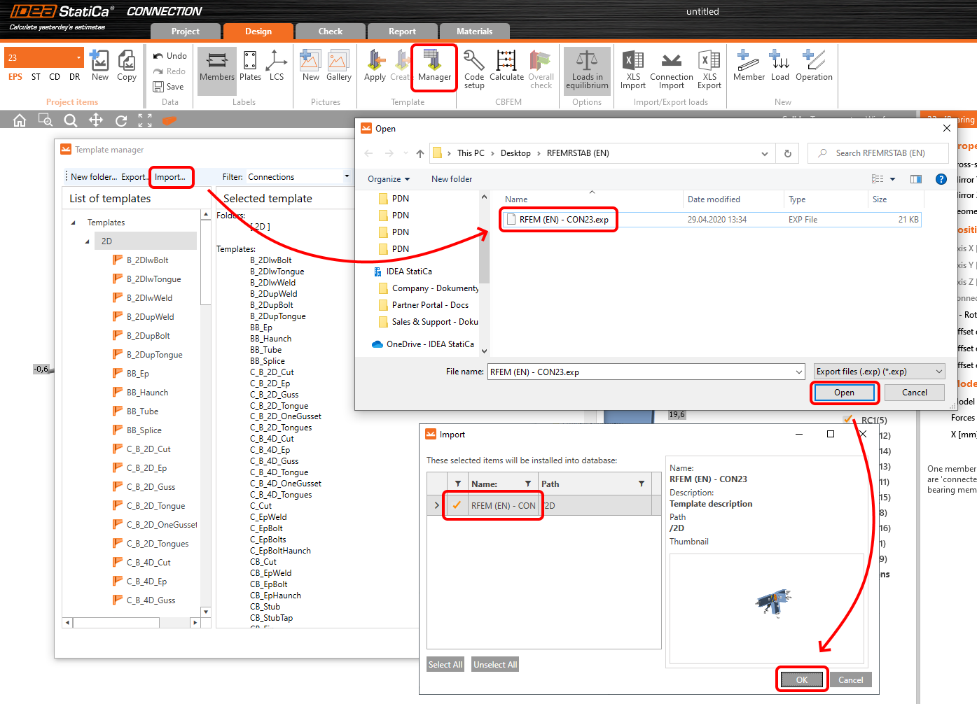
Then click Apply and select the template.

And select the default bolt assembly for this connection item.

The design template is applied and you can just click Save and close the Connection module, or you can run the analysis now and code-check the joint as well.

You have configured and designed both joints that are a part of the analyzed member. Now select the member in the list and click Finish.

And open it in the Member module.

All the data such as geometry and loads have been imported, and all connections have been already designed. The model is ready to be analyzed, but first, let's add some openings to the web of the member. Right-click on Operations in the tree menu and pick the operation Opening.

Edit the parameters of the operation, change the size and shape to N-gon (polygon with n sides) and multiply the openings number.

4 Check
Move to the Check tab, select the MNA (Materially Nonlinear Analysis) and start the analysis by clicking Calculate in the ribbon. The analysis model is automatically generated, the calculation is performed and you can see the overall check displayed together with basic values of check results.

In the next step, switch the CBFEM analysis type to LBA (Linear buckling analysis) and run the analysis again by clicking Calculate.

When the analysis is finished, you can browse the buckling shape factors in the tab, and by selecting some, e.g. buckling shape 1, you can see it visualized in the 3D window. Selecting the Uy results display highlights the deformation trend.

Now you can calculate the GMNIA (geometrically and materially non-linear analysis with imperfections). According to EN 1993-1-1, choose the most critical buckling shape or a combination of buckling shapes and input the initial imperfection of the critical beam. In this case, buckling shape 1 is the most critical one. Switch to the GMNIA tab in the right panel and determine the imperfection of 10 mm (0,5xL/300 = 0,5*6000/300 = 10 mm) to type in as the Amplitude in column 1. Click the Calculate button, for this analysis, the calculation may take several minutes.

The member passed the code-checks with applied initial imperfections and we can browse the results such as stress distribution and internal forces diagram.

5 Report
At last, go to the tab Report. IDEA StatiCa offers a fully customizable report to be printed out or saved in .doc editable format.

You have imported a member from RFEM and designed and code-checked it according to Eurocode (EN).
6 Synchronize models
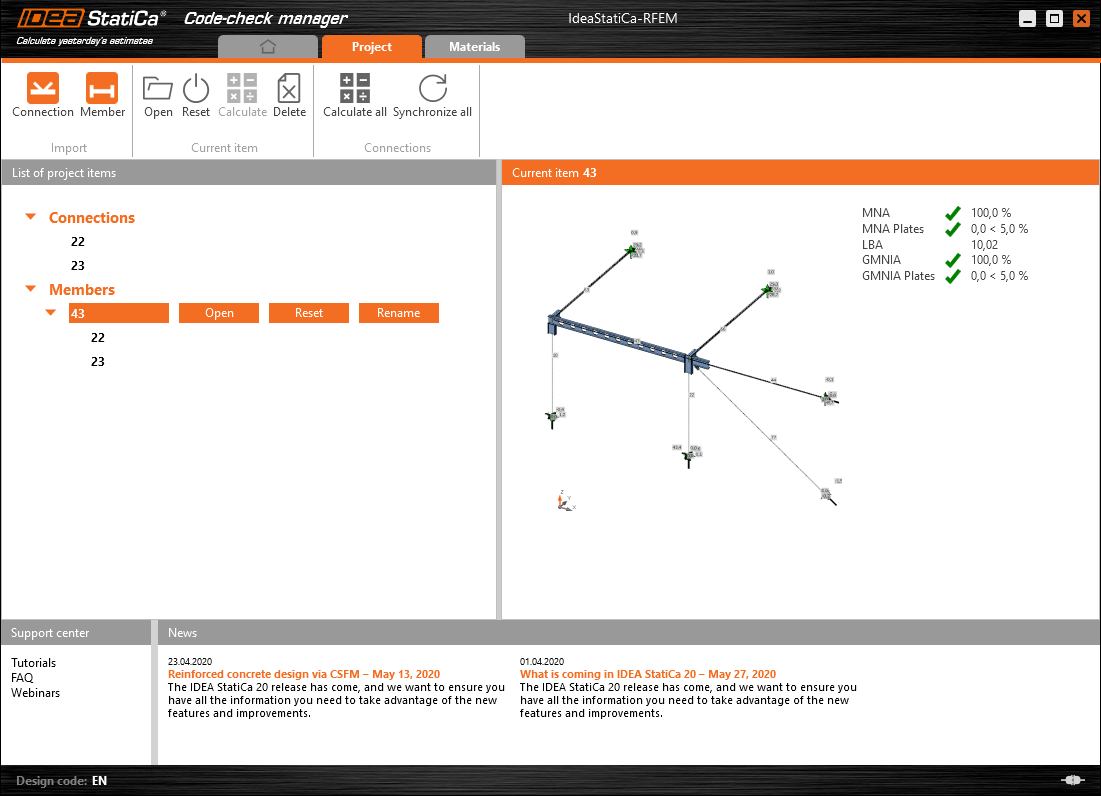
Save the project in IDEA StatiCa Member and close it. All structural details imported from RFEM/RSTAB project to IDEA StatiCa are kept on the list. The Code-check manager provides useful commands for further processing of the imported items.
To demonstrate the synchronize function, change the cross-section of the analyzed member.

Then, recalculate the project in RFEM/RSTAB and open the Code-check manager again.
Select the member from the list and click Synchronize all.
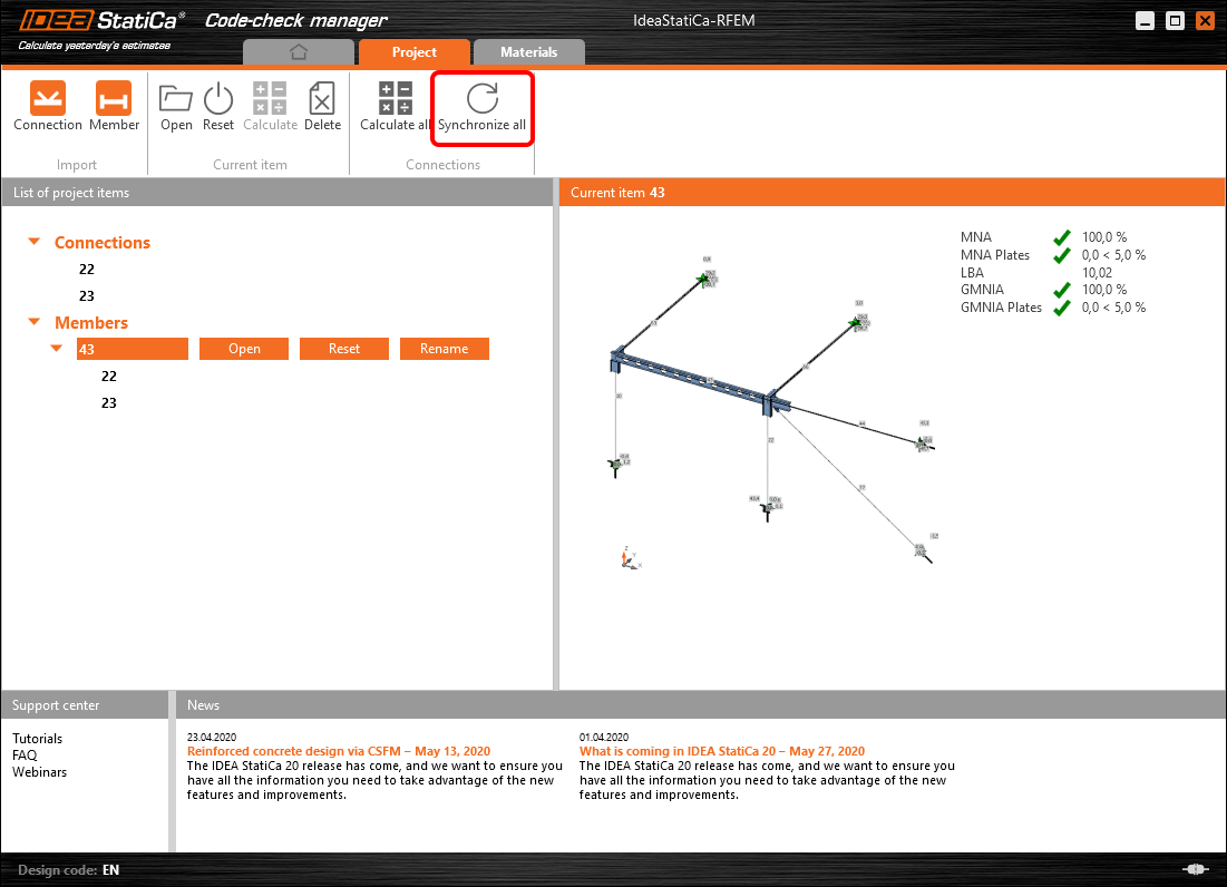
The geometry and load effects were updated and you can click Open to check the project item.

IDEA StatiCa opens and you can see the updated geometry while the design operations keep the settings.

You can check and adjust the design, recalculate and code-check the member, save and close it. Then you can continue importing and code-checking more joints or members.
Limitazioni note per RFEM/RSTAB
Per ora, il collegamento funziona per un'ampia varietà di collegamenti/giunti. Tuttavia, si prega di tenere conto delle funzionalità non ancora supportate.
Limitazione: Non è possibile esportare un elemento con un'estremità a mensola rastremata o un altro tipo di estremità conica o di altra forma.
Soluzione alternativa: La mensola rastremata viene ignorata e può essere modellata successivamente in IDEA StatiCa
Limitazione: L'esportazione di un collegamento su un elemento continuo senza un nodo intermedio non funziona.
Soluzione alternativa: Aggiungere il nodo intermedio utilizzando il comando per gli elementi "Divide Member Using n Intermediate Nodes". L'opzione "Place/Create new nodes without dividing it" per mantenere l'elemento continuo funzionerà solo in RFEM 5. L'applicazione Checkbot può riconoscere solo il tipo di nodo "Standard"; i tipi di nodo "On Member" o "On Line" non verranno riconosciuti.
RFEM 6:

RFEM 5:

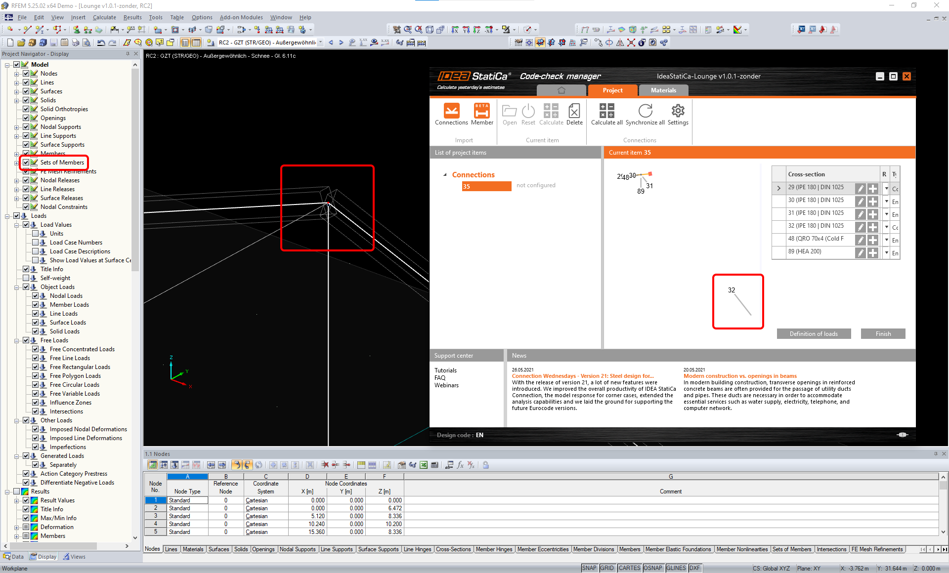
Limitazione: L'esportazione di un nodo quando l'impostazione di visualizzazione "Sets of member" è attiva può causare un trasferimento di dati errato per alcune sezioni trasversali degli elementi e l'importazione di elementi aggiuntivi o un messaggio di errore.
Soluzione alternativa: Disattivare "Sets of member" e ripetere l'esportazione del nodo.
Limitazione: Eccentricità geometrica – il nodo del giunto non si trova nel punto centrale.
Soluzione alternativa: RFEM/RSTAB offre diversi modi per inserire le eccentricità. L'inserimento dell'eccentricità tramite le coordinate locali x,y,z causa difficoltà nella trasformazione dei dati verso IDEA StatiCa a causa della varietà di opzioni del sistema di riferimento in RFEM/RSTAB. In tal caso, utilizzare invece l'inserimento dell'eccentricità tramite le coordinate globali X,Y,Z.

Limitazione: L'oggetto "Joint" non è supportato per il trasferimento dei dati e blocca l'importazione della geometria e dei carichi dei collegamenti in Checkbot.
Soluzione alternativa: Eliminare gli oggetti "Joint", ricalcolare il modello e importare i collegamenti.

Limitazione: L'importazione di casi di carico dinamici e combinazioni di carico contenenti carichi dinamici non è supportata.
Soluzione alternativa: Modificare la definizione dei casi di carico dinamici in RFEM/RSTAB in casi di carico standard con ciascuna direzione delle ampiezze separatamente, oppure inserire le forze interne in IDEA StatiCa manualmente o tramite l'importazione XLS.

Limitazione: L'importazione di sistemi di riferimento locale (LCS) non standard non è supportata.
Soluzione alternativa: Utilizzare solo le impostazioni supportate degli assi locali xyz.
Vedere la figura:
- verde = impostazioni supportate
- rosso = impostazioni non supportate

Limitazione di RFEM5/RSTAB8: Casi di carico assegnati a vari gruppi di carico per diverse Combinazioni di Risultati.
Ciò significa che in IDEA StatiCa ogni caso di carico è assegnato a un solo gruppo di carico per tutte le combinazioni, mentre in Dlubal un caso di carico può essere assegnato a un gruppo diverso in diverse Combinazioni di Risultati.
Soluzione alternativa: Per tutte le Combinazioni di Risultati, assegnare sempre i casi di carico allo stesso gruppo di carico. In alternativa, è possibile creare combinazioni esatte utilizzando lo strumento "Load Combinations".


Limitazione di RFEM5/RSTAB8: Gli effetti di tutti i casi di carico con lo stesso nome (ovvero elencati più volte nella combinazione di risultati) vengono sommati insieme al coefficiente corrispondente in Checkbot. Ciò può portare al raddoppio di determinati casi di carico (es. 1*LC7 +1*LC7=2*LC7) e all'annullamento di altri casi di carico nella combinazione (es. 1*LC9 -1*LC9= 0*LC9)!
Soluzione alternativa: Non utilizzare gli stessi casi di carico nella stessa Combinazione di Risultati più di una volta in RFEM o RSTAB. Se si desidera utilizzare il gruppo di carico in RFEM e RSTAB e assegnare lo stesso caso di carico a una Combinazione di Risultati una volta con segno positivo e una volta con segno negativo, procedere diversamente con 2 Combinazioni di Risultati o Combinazioni di Carico indipendenti.

Limitazione: Il riferimento ad altre Combinazioni di Risultati all'interno delle Combinazioni di Risultati non è supportato per l'importazione in Checkbot.
Soluzione alternativa: Aggiungere i casi di carico alla Combinazione di Risultati invece di aggiungere altre Combinazioni di Risultati.

Limitazione: Le forze interne non vengono importate in Checkbot se i valori dei risultati corrispondenti sono disattivati nel Result Table Manager.
Soluzione alternativa: Aprire Results → Result Table Manager e attivare i valori richiesti. Assicurarsi che le seguenti opzioni siano abilitate:
- Righe: Inizio elemento, Punti interni, Fine elemento
- Colonne: Forze interne, Momenti interni
