
RFEM/RSTAB BIM link for steel member design (EN) - OLD
1 How to activate the link
- Install the latest version of IDEA StatiCa
- Make sure you are using a supported version of RFEM/RSTAB
- You need to have the COM module installed in RFEM/RSTAB to create the BIM link with IDEA StatiCa.
IDEA StatiCa automatically integrates the BIM link into your CAD/CAE software during its installation. You can check the status and activate more BIM links for other software installed later in the BIM link installer.
Open IDEA StatiCa and navigate to the panel BIM and open the BIM link installer. A notification "Run as administrator" may appear, please confirm with the Yes button.
Select the software to integrate the IDEA StatiCa BIM link, click the Install button and check the status.

Note: RFEM/RSTAB BIM link provides importing only under the Eurocode (EN) standard.
2 How to use the link
First, open the source file RFEM.rf5 from the provided files for download (at the bottom of this tutorial) and open it in RFEM/RSTAB. There navigate to menu Add-on Modules then External Modules and run IDEA Statica Steel (for RFEM6/RSTAB9 use this process).

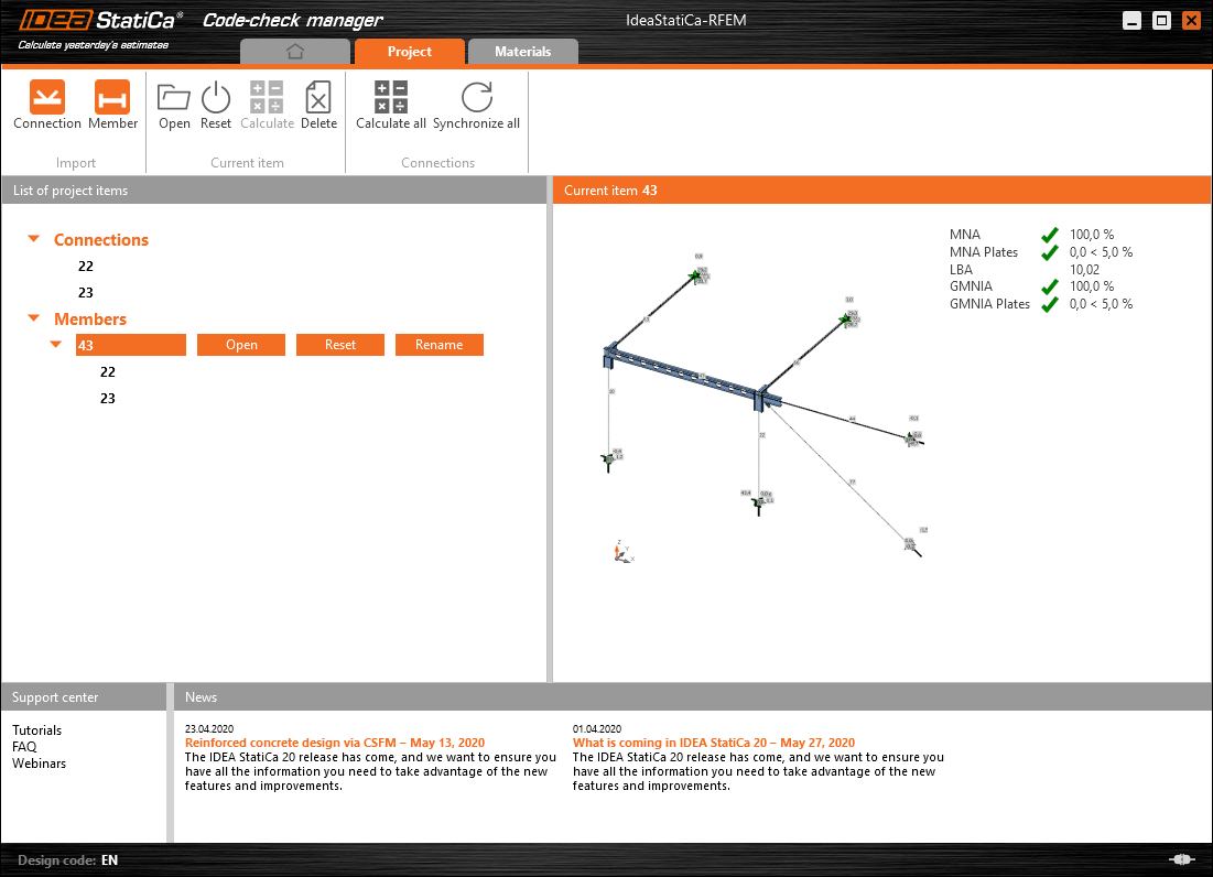
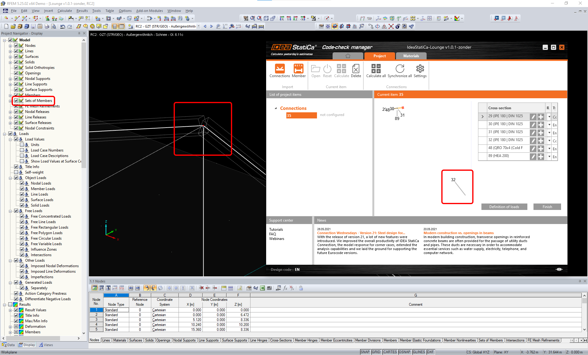
The Code-check manager opens and you can start the import process. Select one beam or column in the RFEM/RSTAB model and click Member to import it for the analysis in IDEA StatiCa Member under the EN code.

The member is added to the list together with corresponding joints and by selecting it the wireframe model together with the tab of cross-sections is displayed. In this step, you can manage the imported load cases. Leave the default settings and start configuring the connections first.

3 Design
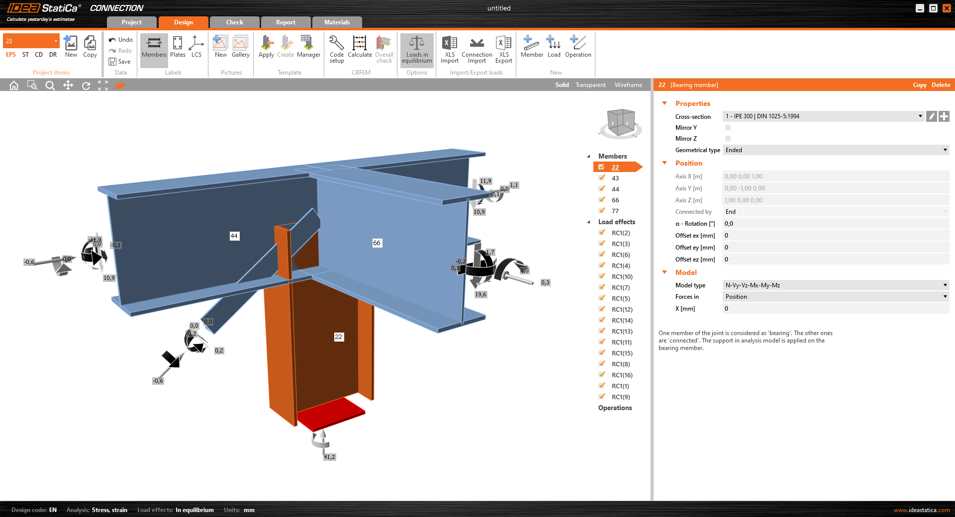
Select node 22 in the list, click Finish, and open it in the Connection module to configure the connections by following the tutorial BIM link tutorial Connection - RFEM/RSTAB (EN) from chapter 3 on.

After that, select node 23, again click Finish, and open it to design the connections.

Instead of designing all the connections of this joint by adding the operations, take advantage of the predefined template from the provided files for download in this tutorial.
Open the template Manager and import the template into your IDEA StatiCa template database.
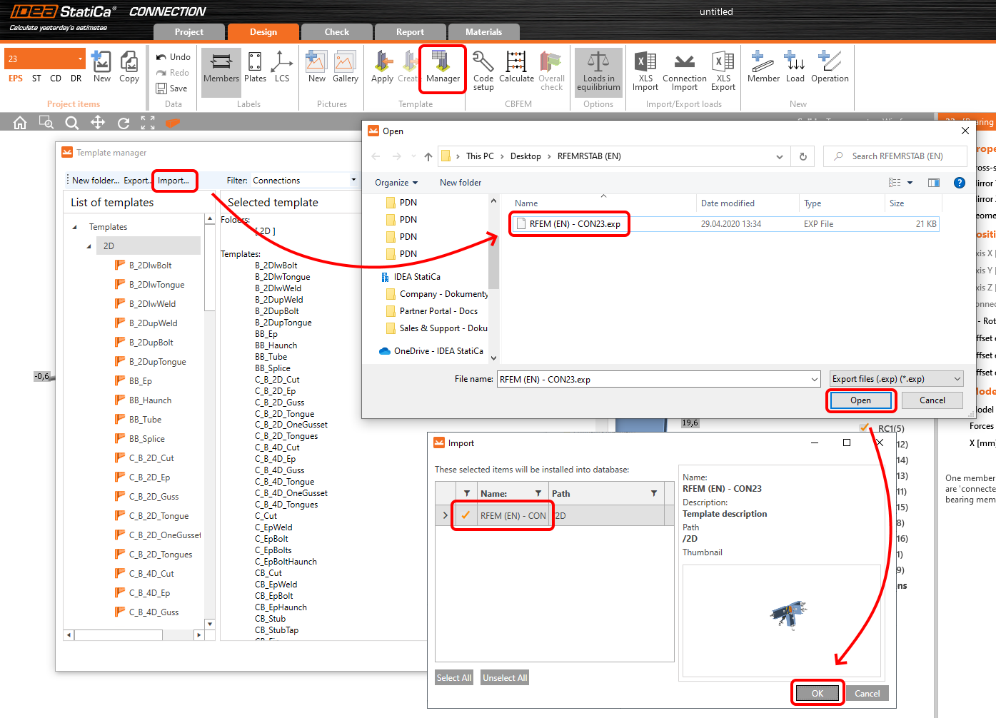
Then click Apply and select the template.

And select the default bolt assembly for this connection item.

The design template is applied and you can just click Save and close the Connection module, or you can run the analysis now and code-check the joint as well.

You have configured and designed both joints that are a part of the analyzed member. Now select the member in the list and click Finish.

And open it in the Member module.

All the data such as geometry and loads have been imported, and all connections have been already designed. The model is ready to be analyzed, but first, let's add some openings to the web of the member. Right-click on Operations in the tree menu and pick the operation Opening.

Edit the parameters of the operation, change the size and shape to N-gon (polygon with n sides) and multiply the openings number.

4 Check
Move to the Check tab, select the MNA (Materially Nonlinear Analysis) and start the analysis by clicking Calculate in the ribbon. The analysis model is automatically generated, the calculation is performed and you can see the overall check displayed together with basic values of check results.

In the next step, switch the CBFEM analysis type to LBA (Linear buckling analysis) and run the analysis again by clicking Calculate.

When the analysis is finished, you can browse the buckling shape factors in the tab, and by selecting some, e.g. buckling shape 1, you can see it visualized in the 3D window. Selecting the Uy results display highlights the deformation trend.

Now you can calculate the GMNIA (geometrically and materially non-linear analysis with imperfections). According to EN 1993-1-1, choose the most critical buckling shape or a combination of buckling shapes and input the initial imperfection of the critical beam. In this case, buckling shape 1 is the most critical one. Switch to the GMNIA tab in the right panel and determine the imperfection of 10 mm (0,5xL/300 = 0,5*6000/300 = 10 mm) to type in as the Amplitude in column 1. Click the Calculate button, for this analysis, the calculation may take several minutes.

The member passed the code-checks with applied initial imperfections and we can browse the results such as stress distribution and internal forces diagram.

5 Report
At last, go to the tab Report. IDEA StatiCa offers a fully customizable report to be printed out or saved in .doc editable format.

You have imported a member from RFEM and designed and code-checked it according to Eurocode (EN).
6 Synchronize models
Save the project in IDEA StatiCa Member and close it. All structural details imported from RFEM/RSTAB project to IDEA StatiCa are kept on the list. The Code-check manager provides useful commands for further processing of the imported items.
To demonstrate the synchronize function, change the cross-section of the analyzed member.

Then, recalculate the project in RFEM/RSTAB and open the Code-check manager again.
Select the member from the list and click Synchronize all.
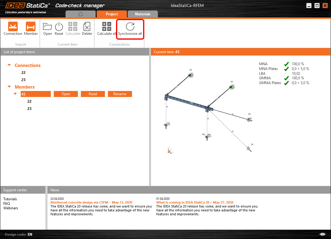
The geometry and load effects were updated and you can click Open to check the project item.

IDEA StatiCa opens and you can see the updated geometry while the design operations keep the settings.

You can check and adjust the design, recalculate and code-check the member, save and close it. Then you can continue importing and code-checking more joints or members.
Limitations connues pour RFEM/RSTAB
Pour l'instant, le lien fonctionne pour une grande variété d'assemblages/joints. Veuillez toutefois tenir compte des fonctionnalités non encore prises en charge.
Limitation : L'exportation d'une poutre avec une extrémité à jarret ou un autre type d'extrémité de poutre conique ou de forme particulière n'est pas possible.
Solution de contournement : Le jarret est ignoré et peut être modélisé ultérieurement dans IDEA StatiCa
Limitation : L'exportation d'un assemblage sur un élément continu sans nœud intermédiaire ne fonctionne pas.
Solution de contournement : Ajoutez le nœud intermédiaire à l'aide de la commande pour les éléments « Diviser l'élément en utilisant n nœuds intermédiaires ». L'option « Placer/Créer de nouveaux nœuds sans le diviser » pour conserver l'élément continu ne fonctionnera que dans RFEM 5. L'application Checkbot ne reconnaît que le type de nœud « Standard » ; les types de nœuds « Sur élément » ou « Sur ligne » ne seront pas reconnus.
RFEM 6 :

RFEM 5 :

Limitation : L'exportation d'un nœud lorsque le paramètre d'affichage « Ensembles d'éléments » est activé peut entraîner un transfert de données incorrect pour certaines sections transversales d'éléments, ainsi que l'importation d'éléments supplémentaires ou un message d'erreur.
Solution de contournement : Désactivez « Ensembles d'éléments » et répétez l'exportation du nœud.
Limitation : Excentricité géométrique – le nœud de l'assemblage n'est pas au point central.
Solution de contournement : RFEM/RSTAB offre plusieurs modes de saisie des excentricités. La saisie de l'excentricité à l'aide des coordonnées locales x, y, z entraîne des difficultés lors de la transformation des données vers IDEA StatiCa en raison de la variété des options de système de coordonnées dans RFEM/RSTAB. Le cas échéant, veuillez utiliser la saisie de l'excentricité en coordonnées globales X, Y, Z à la place.

Limitation : L'objet « Joint » n'est pas pris en charge pour le transfert de données et bloque l'importation de la géométrie et des charges des assemblages vers Checkbot.
Solution de contournement : Supprimez les objets « Joint », recalculez le modèle et importez les assemblages.

Limitation : L'importation des cas de charge dynamiques et des combinaisons de charges contenant des charges dynamiques n'est pas prise en charge.
Solution de contournement : Modifiez la définition des cas de charge dynamiques dans RFEM/RSTAB en cas de charge standard avec chaque direction d'amplitude séparément, ou saisissez les efforts intérieurs dans IDEA StatiCa manuellement ou via l'importation XLS.

Limitation : L'importation de repères locaux (LCS) non standard n'est pas prise en charge.
Solution de contournement : Utilisez uniquement les paramètres pris en charge des axes locaux xyz.
Voir la figure :
- vert = paramètres pris en charge
- rouge = paramètres non pris en charge

Limitation de RFEM5/RSTAB8 : Cas de charge affectés à différents groupes de charges pour différentes combinaisons de résultats.
Cela signifie que dans IDEA StatiCa, chaque cas de charge est affecté à un seul groupe de charges pour toutes les combinaisons, tandis que dans Dlubal, un cas de charge peut être affecté à un groupe différent dans différentes combinaisons de résultats.
Solution de contournement : Pour toutes les combinaisons de résultats, affectez toujours les cas de charge au même groupe de charges. Vous pouvez également créer des combinaisons exactes à l'aide de l'outil « Combinaisons de charges ».


Limitation de RFEM5/RSTAB8 : Les effets de tous les cas de charge portant le même nom (c'est-à-dire listés plusieurs fois dans la combinaison de résultats) sont additionnés avec le coefficient correspondant dans Checkbot. Cela peut entraîner le doublement de certains cas de charge (ex. : 1*LC7 +1*LC7=2*LC7) et l'annulation d'autres cas de charge dans la combinaison (ex. : 1*LC9 -1*LC9= 0*LC9) !
Solution de contournement : N'utilisez pas les mêmes cas de charge plus d'une fois dans la même combinaison de résultats dans RFEM ou RSTAB. Si vous souhaitez utiliser le groupe de charges dans RFEM et RSTAB et affecter le même cas de charge à une combinaison de résultats une fois avec un signe positif et une fois avec un signe négatif, procédez différemment avec 2 combinaisons de résultats ou combinaisons de charges indépendantes.

Limitation : La référence à d'autres combinaisons de résultats dans les combinaisons de résultats n'est pas prise en charge pour l'importation dans Checkbot.
Solution de contournement : Ajoutez des cas de charge à la combinaison de résultats au lieu d'ajouter d'autres combinaisons de résultats.

Limitation : Les efforts intérieurs ne sont pas importés dans Checkbot si les valeurs de résultats correspondantes sont désactivées dans le gestionnaire de tableaux de résultats.
Solution de contournement : Ouvrez Résultats → Gestionnaire de tableaux de résultats et activez les valeurs requises. Assurez-vous que les options suivantes sont activées :
- Lignes : Débuts d'éléments, Points intermédiaires, Fins d'éléments
- Colonnes : Efforts intérieurs, Moments intérieurs
