
RFEM/RSTAB BIM link for steel member design (EN) - OLD
1 How to activate the link
- Install the latest version of IDEA StatiCa
- Make sure you are using a supported version of RFEM/RSTAB
- You need to have the COM module installed in RFEM/RSTAB to create the BIM link with IDEA StatiCa.
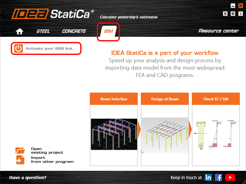
IDEA StatiCa automatically integrates the BIM link into your CAD/CAE software during its installation. You can check the status and activate more BIM links for other software installed later in the BIM link installer.
Open IDEA StatiCa and navigate to the panel BIM and open the BIM link installer. A notification "Run as administrator" may appear, please confirm with the Yes button.
Select the software to integrate the IDEA StatiCa BIM link, click the Install button and check the status.

Note: RFEM/RSTAB BIM link provides importing only under the Eurocode (EN) standard.
2 How to use the link
First, open the source file RFEM.rf5 from the provided files for download (at the bottom of this tutorial) and open it in RFEM/RSTAB. There navigate to menu Add-on Modules then External Modules and run IDEA Statica Steel (for RFEM6/RSTAB9 use this process).

The Code-check manager opens and you can start the import process. Select one beam or column in the RFEM/RSTAB model and click Member to import it for the analysis in IDEA StatiCa Member under the EN code.

The member is added to the list together with corresponding joints and by selecting it the wireframe model together with the tab of cross-sections is displayed. In this step, you can manage the imported load cases. Leave the default settings and start configuring the connections first.

3 Design
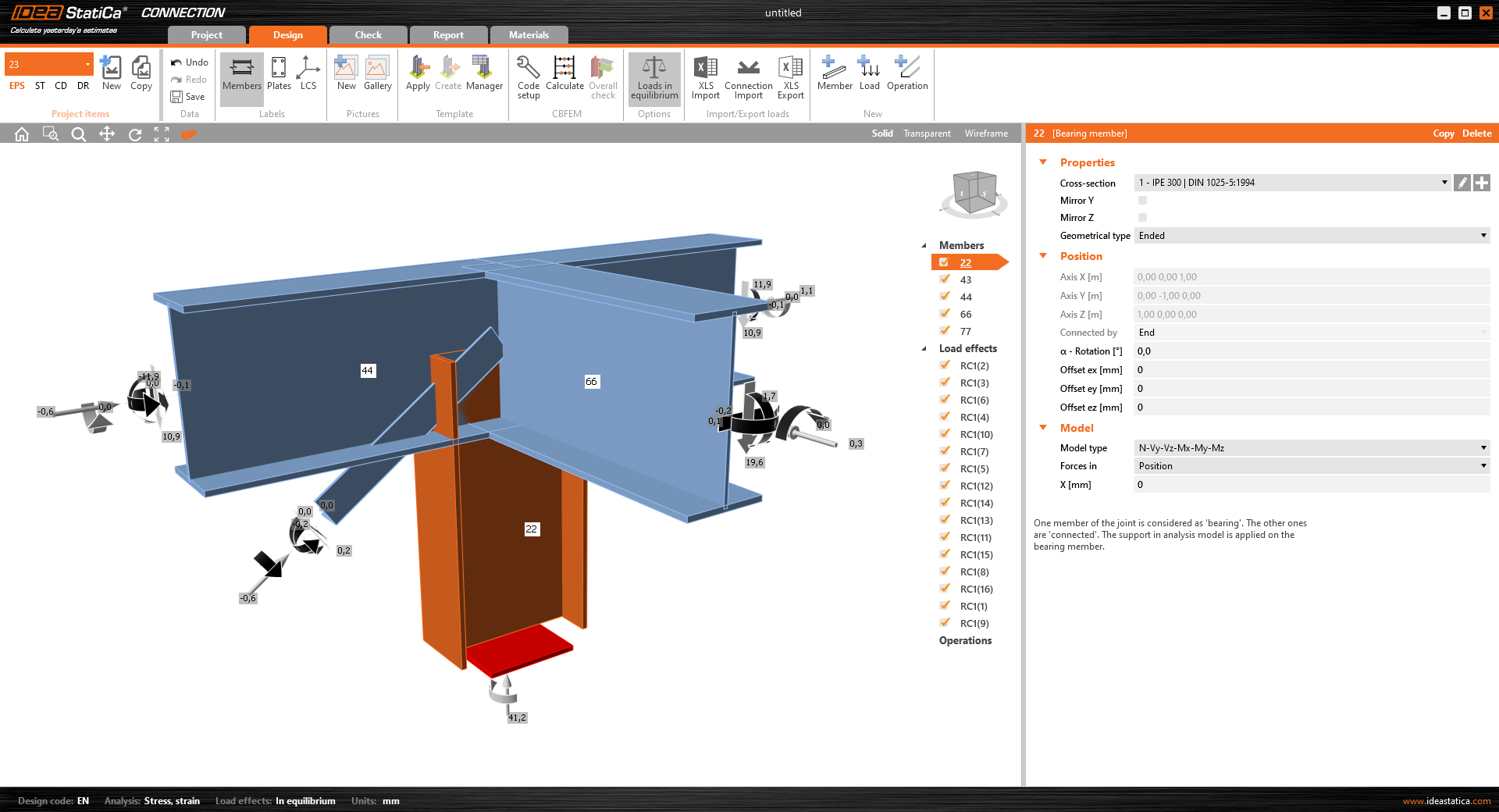
Select node 22 in the list, click Finish, and open it in the Connection module to configure the connections by following the tutorial BIM link tutorial Connection - RFEM/RSTAB (EN) from chapter 3 on.

After that, select node 23, again click Finish, and open it to design the connections.

Instead of designing all the connections of this joint by adding the operations, take advantage of the predefined template from the provided files for download in this tutorial.
Open the template Manager and import the template into your IDEA StatiCa template database.
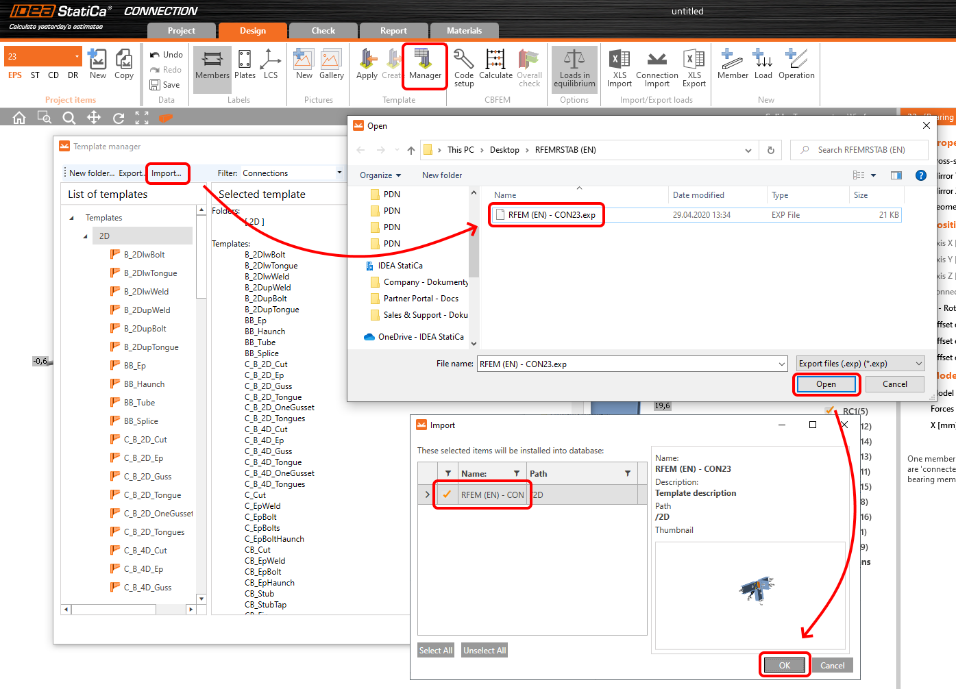
Then click Apply and select the template.

And select the default bolt assembly for this connection item.

The design template is applied and you can just click Save and close the Connection module, or you can run the analysis now and code-check the joint as well.

You have configured and designed both joints that are a part of the analyzed member. Now select the member in the list and click Finish.

And open it in the Member module.

All the data such as geometry and loads have been imported, and all connections have been already designed. The model is ready to be analyzed, but first, let's add some openings to the web of the member. Right-click on Operations in the tree menu and pick the operation Opening.

Edit the parameters of the operation, change the size and shape to N-gon (polygon with n sides) and multiply the openings number.

4 Check
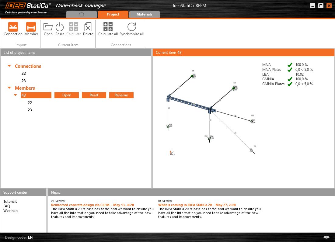
Move to the Check tab, select the MNA (Materially Nonlinear Analysis) and start the analysis by clicking Calculate in the ribbon. The analysis model is automatically generated, the calculation is performed and you can see the overall check displayed together with basic values of check results.

In the next step, switch the CBFEM analysis type to LBA (Linear buckling analysis) and run the analysis again by clicking Calculate.

When the analysis is finished, you can browse the buckling shape factors in the tab, and by selecting some, e.g. buckling shape 1, you can see it visualized in the 3D window. Selecting the Uy results display highlights the deformation trend.

Now you can calculate the GMNIA (geometrically and materially non-linear analysis with imperfections). According to EN 1993-1-1, choose the most critical buckling shape or a combination of buckling shapes and input the initial imperfection of the critical beam. In this case, buckling shape 1 is the most critical one. Switch to the GMNIA tab in the right panel and determine the imperfection of 10 mm (0,5xL/300 = 0,5*6000/300 = 10 mm) to type in as the Amplitude in column 1. Click the Calculate button, for this analysis, the calculation may take several minutes.

The member passed the code-checks with applied initial imperfections and we can browse the results such as stress distribution and internal forces diagram.

5 Report
At last, go to the tab Report. IDEA StatiCa offers a fully customizable report to be printed out or saved in .doc editable format.

You have imported a member from RFEM and designed and code-checked it according to Eurocode (EN).
6 Synchronize models
Save the project in IDEA StatiCa Member and close it. All structural details imported from RFEM/RSTAB project to IDEA StatiCa are kept on the list. The Code-check manager provides useful commands for further processing of the imported items.
To demonstrate the synchronize function, change the cross-section of the analyzed member.

Then, recalculate the project in RFEM/RSTAB and open the Code-check manager again.
Select the member from the list and click Synchronize all.
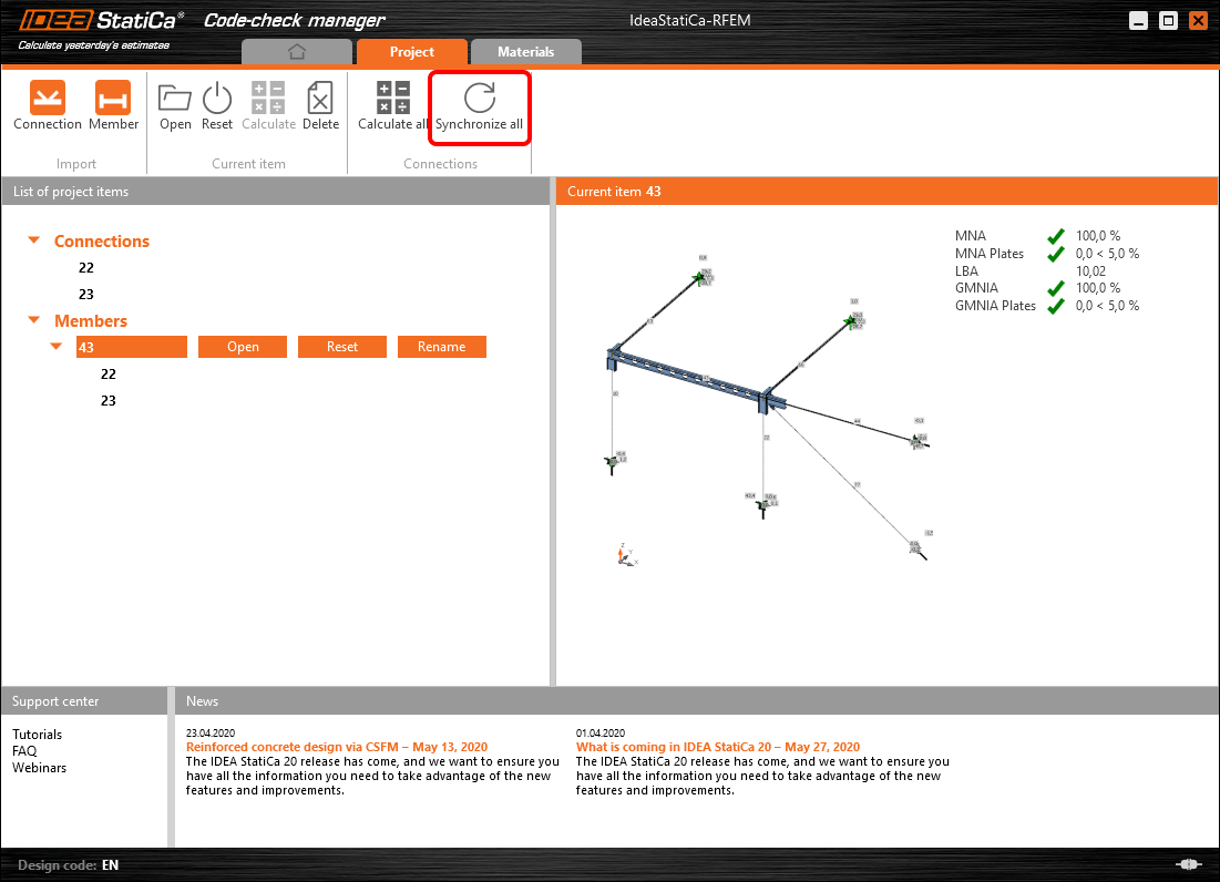
The geometry and load effects were updated and you can click Open to check the project item.

IDEA StatiCa opens and you can see the updated geometry while the design operations keep the settings.

You can check and adjust the design, recalculate and code-check the member, save and close it. Then you can continue importing and code-checking more joints or members.
RFEM/RSTAB의 알려진 제한 사항
현재 이 링크는 다양한 연결/접합부에 대해 작동합니다. 그러나 아직 지원되지 않는 기능을 고려하시기 바랍니다.
제한 사항: 헌치 단부 또는 다른 유형의 원뿔형 또는 기타 형상의 보 단부를 가진 보의 내보내기는 불가능합니다.
해결 방법: 헌치는 무시되며 이후 IDEA StatiCa에서 모델링할 수 있습니다.
제한 사항: 중간 노드 없이 연속 부재의 연결을 내보내는 것은 작동하지 않습니다.
해결 방법: 부재 명령 "Divide Member Using n Intermediate Nodes"를 사용하여 중간 노드를 추가하십시오. 부재를 연속으로 유지하기 위한 "Place/Create new nodes without dividing it" 옵션은 RFEM 5에서만 작동합니다. Checkbot 애플리케이션은 "Standard" 노드 유형만 인식할 수 있으며, "On Member" 또는 "On Line" 노드 유형은 인식되지 않습니다.
RFEM 6:

RFEM 5:

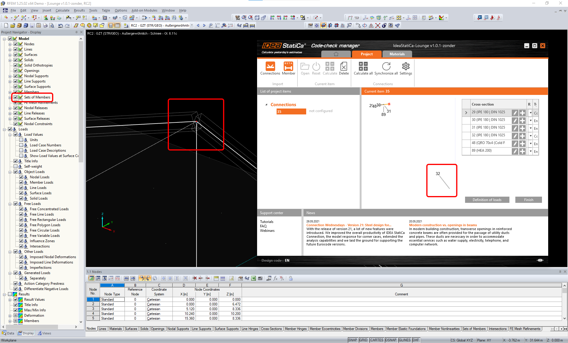
제한 사항: 표시 설정 "Sets of member"가 켜진 상태에서 노드를 내보내면 일부 부재 단면에 대한 잘못된 데이터 전송 및 추가 부재 가져오기 또는 오류 메시지가 발생할 수 있습니다.
해결 방법: "Sets of member"를 끄고 노드 내보내기를 반복하십시오.
제한 사항: 기하학적 편심 – 접합부 노드가 중심점에 있지 않습니다.
해결 방법: RFEM/RSTAB 은 편심 입력에 대한 다양한 방법을 제공합니다. 로컬 x,y,z 좌표를 사용한 편심 입력은 RFEM/RSTAB의 다양한 좌표계 옵션으로 인해 IDEA StatiCa로 데이터를 변환하는 데 어려움을 초래합니다. 이 경우 대신 전역 X,Y,Z 좌표 편심 입력을 사용하십시오.

제한 사항: "Joint" 객체는 데이터 전송에 지원되지 않으며, Checkbot으로의 연결 형상 및 하중 가져오기를 차단합니다.
해결 방법: "Joint" 객체를 삭제하고 모델을 재계산한 후 연결을 가져오십시오.

제한 사항: 동적 하중 케이스 및 동적 하중을 포함하는 하중 조합의 가져오기는 지원되지 않습니다.
해결 방법: RFEM/RSTAB에서 동적 하중 케이스의 정의를 각 진폭 방향별로 별도의 표준 하중 케이스로 변경하거나, IDEA StatiCa에서 수동으로 또는 XLS 가져오기를 사용하여 내력을 입력하십시오.

제한 사항: 비표준 LCS의 가져오기는 지원되지 않습니다.
해결 방법: 지원되는 로컬 축 xyz 설정만 사용하십시오.
그림 참조:
- 녹색 = 지원되는 설정
- 빨간색 = 지원되지 않는 설정

RFEM5/RSTAB8의 제한 사항: 서로 다른 결과 조합에 대해 다양한 하중 그룹에 할당된 하중 케이스.
이는 IDEA StatiCa에서 각 하중 케이스가 모든 조합에 대해 하나의 하중 그룹에만 할당되는 반면, Dlubal에서는 하중 케이스가 서로 다른 결과 조합에서 다른 그룹에 할당될 수 있음을 의미합니다.
해결 방법: 모든 결과 조합에 대해 항상 동일한 하중 그룹에 하중 케이스를 할당하십시오. 또는 "Load Combinations" 도구를 사용하여 정확한 조합을 생성할 수 있습니다.


RFEM5/RSTAB8의 제한 사항: 동일한 이름을 가진 모든 하중 케이스의 효과(즉, 결과 조합에 여러 번 나열된 경우)는 Checkbot에서 해당 계수와 함께 합산됩니다. 이로 인해 특정 하중 케이스가 두 배가 되거나(예: 1*LC7 +1*LC7=2*LC7) 조합에서 다른 하중 케이스가 상쇄될 수 있습니다(예: 1*LC9 -1*LC9= 0*LC9)!
해결 방법: RFEM 또는 RSTAB에서 동일한 결과 조합에 동일한 하중 케이스를 두 번 이상 사용하지 마십시오. RFEM 및 RSTAB에서 하중 그룹을 사용하고 동일한 하중 케이스를 결과 조합에 양의 부호와 음의 부호로 각각 한 번씩 할당하려면, 2개의 독립적인 결과 조합 또는 하중 조합을 사용하여 다르게 처리하십시오.

제한 사항: 결과 조합에서 다른 결과 조합을 참조하는 것은 Checkbot으로의 가져오기에 지원되지 않습니다.
해결 방법: 다른 결과 조합을 추가하는 대신 결과 조합에 하중 케이스를 추가하십시오.

제한 사항: 결과 테이블 관리자에서 해당 결과값이 비활성화된 경우 내력이 Checkbot으로 가져오기되지 않습니다.
해결 방법: Results → Result Table Manager를 열고 필요한 값을 활성화하십시오. 다음 옵션이 활성화되어 있는지 확인하십시오:
- 행: 부재 시작점, 내부 점, 부재 끝점
- 열: 내력, 내부 모멘트
