
RFEM/RSTAB BIM link for steel member design (EN) - OLD
1 How to activate the link
- Install the latest version of IDEA StatiCa
- Make sure you are using a supported version of RFEM/RSTAB
- You need to have the COM module installed in RFEM/RSTAB to create the BIM link with IDEA StatiCa.
IDEA StatiCa automatically integrates the BIM link into your CAD/CAE software during its installation. You can check the status and activate more BIM links for other software installed later in the BIM link installer.
Open IDEA StatiCa and navigate to the panel BIM and open the BIM link installer. A notification "Run as administrator" may appear, please confirm with the Yes button.
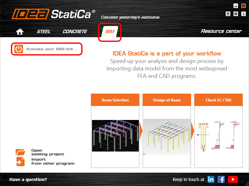
Select the software to integrate the IDEA StatiCa BIM link, click the Install button and check the status.

Note: RFEM/RSTAB BIM link provides importing only under the Eurocode (EN) standard.
2 How to use the link
First, open the source file RFEM.rf5 from the provided files for download (at the bottom of this tutorial) and open it in RFEM/RSTAB. There navigate to menu Add-on Modules then External Modules and run IDEA Statica Steel (for RFEM6/RSTAB9 use this process).

The Code-check manager opens and you can start the import process. Select one beam or column in the RFEM/RSTAB model and click Member to import it for the analysis in IDEA StatiCa Member under the EN code.

The member is added to the list together with corresponding joints and by selecting it the wireframe model together with the tab of cross-sections is displayed. In this step, you can manage the imported load cases. Leave the default settings and start configuring the connections first.

3 Design
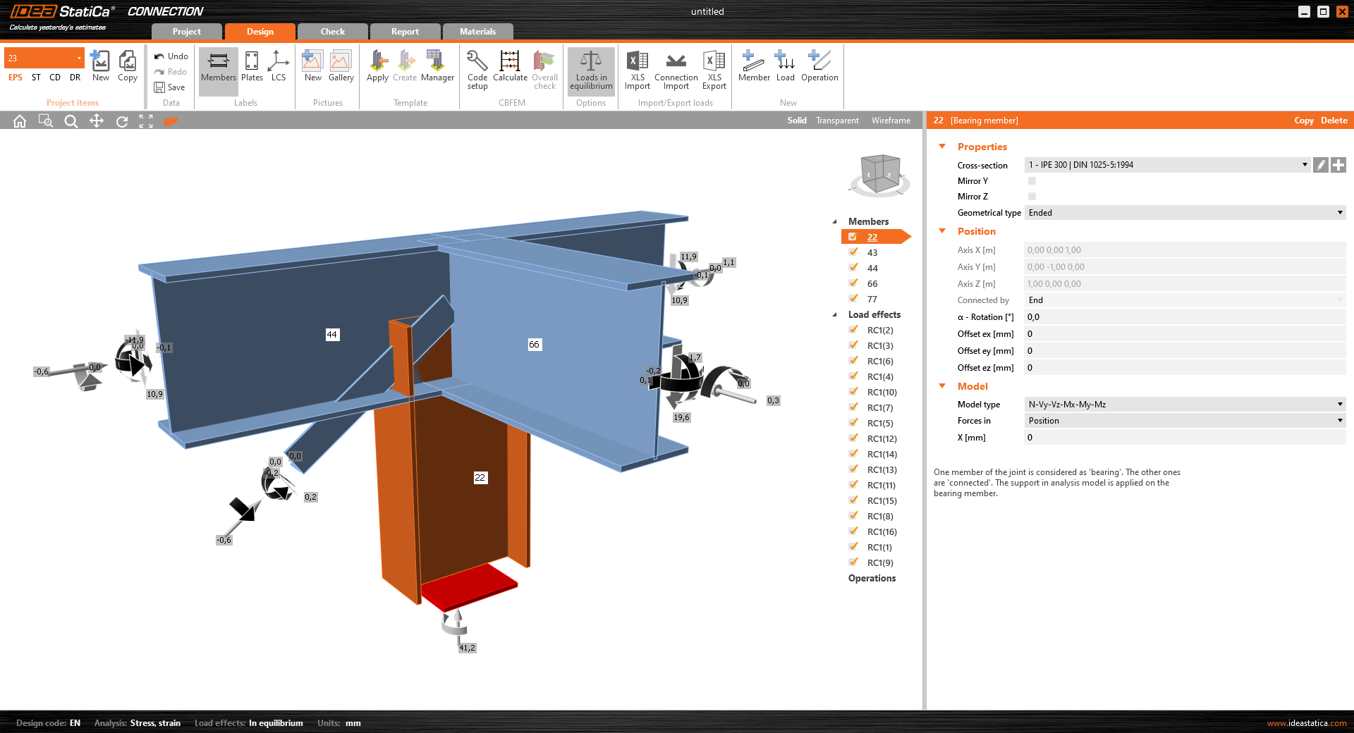
Select node 22 in the list, click Finish, and open it in the Connection module to configure the connections by following the tutorial BIM link tutorial Connection - RFEM/RSTAB (EN) from chapter 3 on.

After that, select node 23, again click Finish, and open it to design the connections.

Instead of designing all the connections of this joint by adding the operations, take advantage of the predefined template from the provided files for download in this tutorial.
Open the template Manager and import the template into your IDEA StatiCa template database.
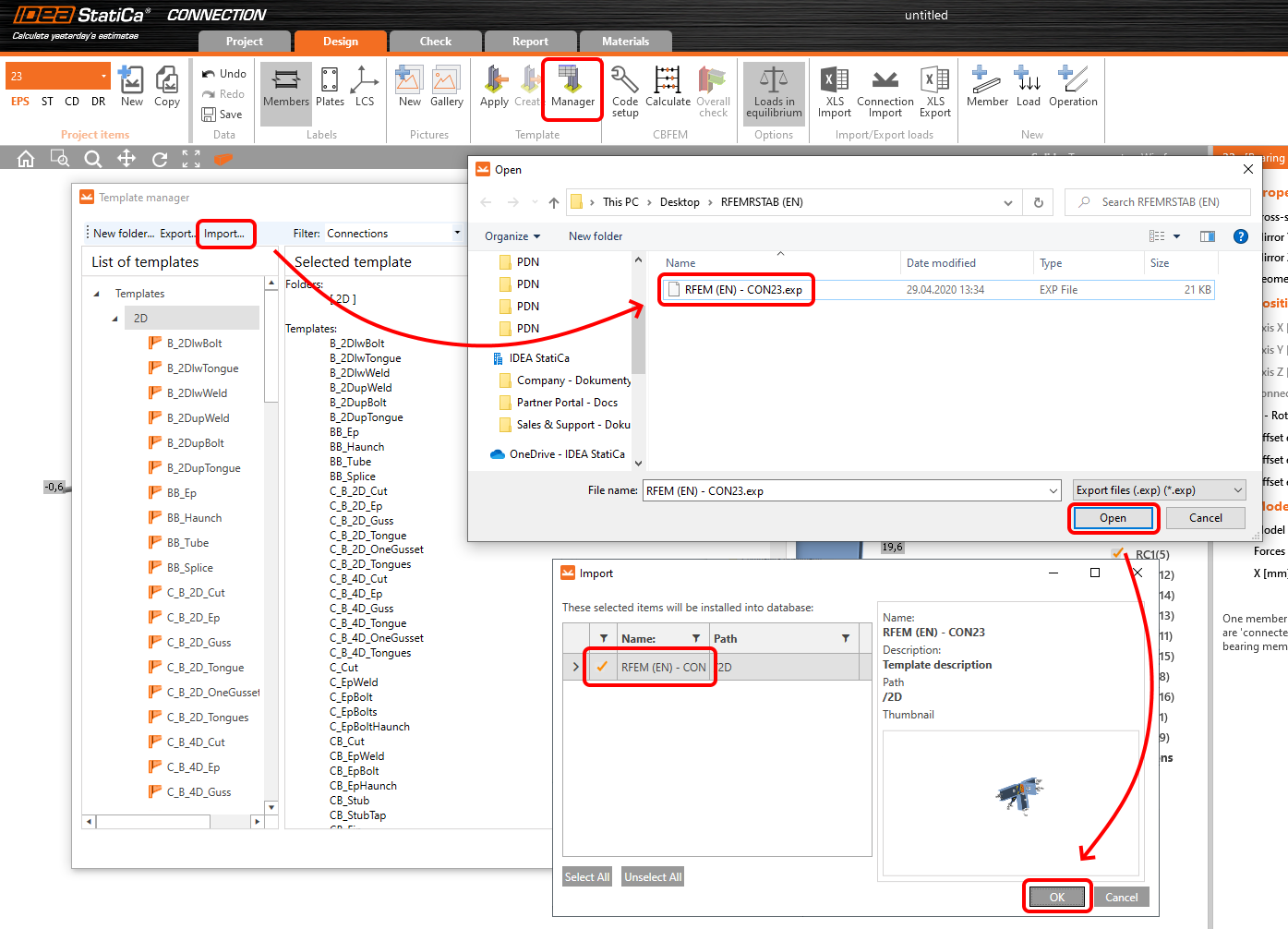
Then click Apply and select the template.

And select the default bolt assembly for this connection item.

The design template is applied and you can just click Save and close the Connection module, or you can run the analysis now and code-check the joint as well.

You have configured and designed both joints that are a part of the analyzed member. Now select the member in the list and click Finish.

And open it in the Member module.

All the data such as geometry and loads have been imported, and all connections have been already designed. The model is ready to be analyzed, but first, let's add some openings to the web of the member. Right-click on Operations in the tree menu and pick the operation Opening.

Edit the parameters of the operation, change the size and shape to N-gon (polygon with n sides) and multiply the openings number.

4 Check
Move to the Check tab, select the MNA (Materially Nonlinear Analysis) and start the analysis by clicking Calculate in the ribbon. The analysis model is automatically generated, the calculation is performed and you can see the overall check displayed together with basic values of check results.

In the next step, switch the CBFEM analysis type to LBA (Linear buckling analysis) and run the analysis again by clicking Calculate.

When the analysis is finished, you can browse the buckling shape factors in the tab, and by selecting some, e.g. buckling shape 1, you can see it visualized in the 3D window. Selecting the Uy results display highlights the deformation trend.

Now you can calculate the GMNIA (geometrically and materially non-linear analysis with imperfections). According to EN 1993-1-1, choose the most critical buckling shape or a combination of buckling shapes and input the initial imperfection of the critical beam. In this case, buckling shape 1 is the most critical one. Switch to the GMNIA tab in the right panel and determine the imperfection of 10 mm (0,5xL/300 = 0,5*6000/300 = 10 mm) to type in as the Amplitude in column 1. Click the Calculate button, for this analysis, the calculation may take several minutes.

The member passed the code-checks with applied initial imperfections and we can browse the results such as stress distribution and internal forces diagram.

5 Report
At last, go to the tab Report. IDEA StatiCa offers a fully customizable report to be printed out or saved in .doc editable format.

You have imported a member from RFEM and designed and code-checked it according to Eurocode (EN).
6 Synchronize models
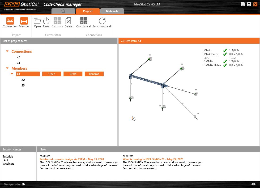
Save the project in IDEA StatiCa Member and close it. All structural details imported from RFEM/RSTAB project to IDEA StatiCa are kept on the list. The Code-check manager provides useful commands for further processing of the imported items.
To demonstrate the synchronize function, change the cross-section of the analyzed member.

Then, recalculate the project in RFEM/RSTAB and open the Code-check manager again.
Select the member from the list and click Synchronize all.
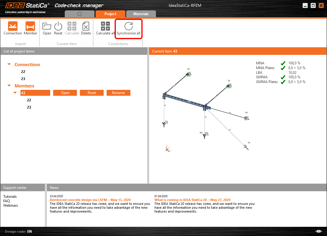
The geometry and load effects were updated and you can click Open to check the project item.

IDEA StatiCa opens and you can see the updated geometry while the design operations keep the settings.

You can check and adjust the design, recalculate and code-check the member, save and close it. Then you can continue importing and code-checking more joints or members.
ข้อจำกัดที่ทราบสำหรับ RFEM/RSTAB
ในขณะนี้ การเชื่อมโยงรองรับการเชื่อมต่อ/จุดต่อหลากหลายประเภท อย่างไรก็ตาม โปรดคำนึงถึงฟังก์ชันที่ยังไม่รองรับในปัจจุบัน
ข้อจำกัด: ไม่สามารถส่งออกคานที่มีปลายแบบ haunch หรือปลายคานรูปทรงกรวยหรือรูปทรงอื่นๆ ได้
วิธีแก้ไข: ส่วนเสริมคานจะถูกละเว้น และสามารถสร้างแบบจำลองได้ภายหลังใน IDEA StatiCa
ข้อจำกัด: การส่งออกการเชื่อมต่อบนชิ้นส่วนต่อเนื่องที่ไม่มี node กลางไม่สามารถทำได้
วิธีแก้ไข: เพิ่ม node กลางโดยใช้คำสั่งสำหรับชิ้นส่วน "Divide Member Using n Intermediate Nodes" ตัวเลือก "Place/Create new nodes without dividing it" เพื่อคงชิ้นส่วนให้ต่อเนื่องจะใช้งานได้เฉพาะใน RFEM 5 เท่านั้น แอปพลิเคชัน Checkbot สามารถรู้จักเฉพาะประเภท node แบบ "Standard" เท่านั้น ประเภท node แบบ "On Member" หรือ "On Line" จะไม่ถูกรู้จัก
RFEM 6:

RFEM 5:

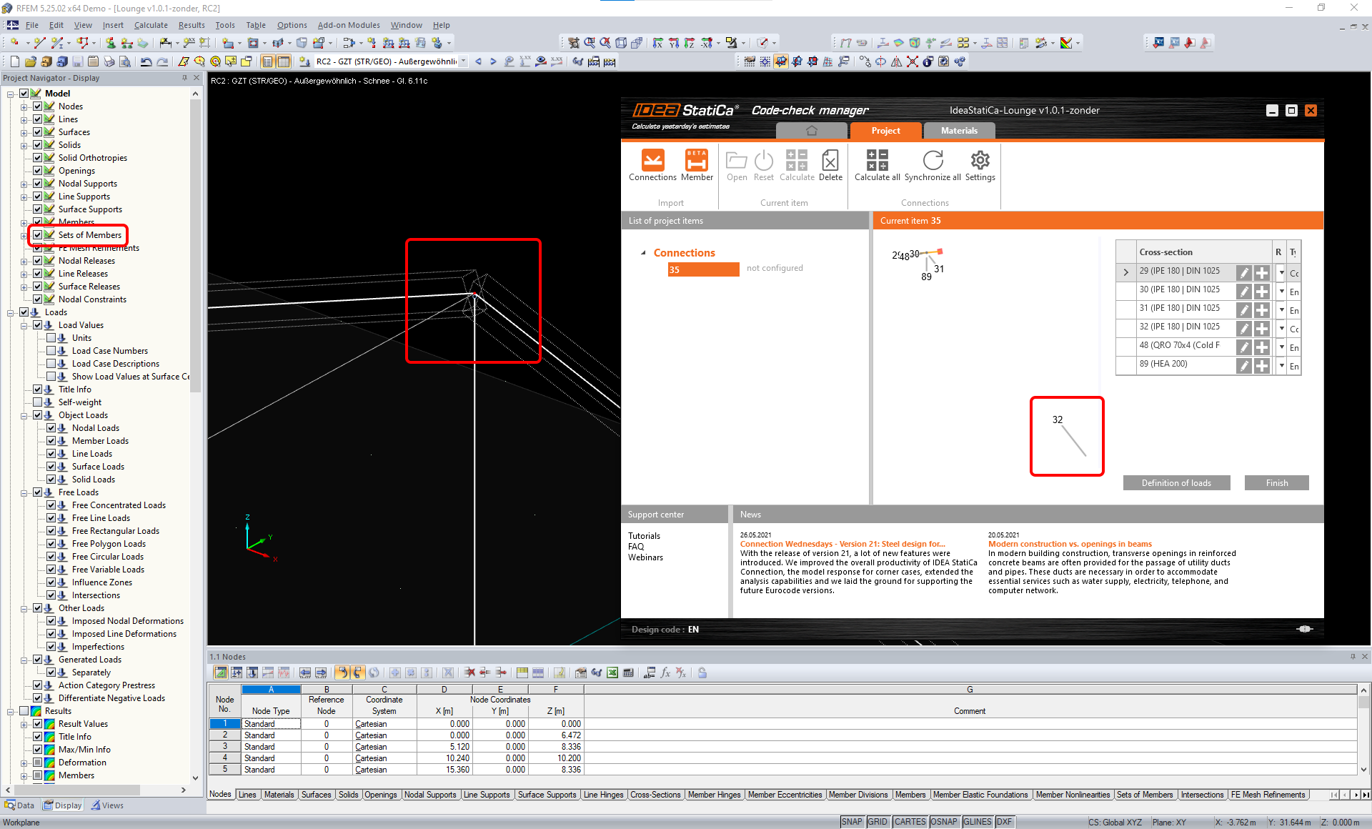
ข้อจำกัด: การส่งออก node เมื่อการตั้งค่าการแสดงผล "Sets of member" เปิดอยู่ อาจทำให้การถ่ายโอนข้อมูลไม่ถูกต้องสำหรับหน้าตัดชิ้นส่วนบางประเภท และนำเข้าชิ้นส่วนเพิ่มเติมหรือแสดงข้อความแสดงข้อผิดพลาด
วิธีแก้ไข: ปิด "Sets of member" และทำการส่งออก node ใหม่อีกครั้ง
ข้อจำกัด: ความเยื้องศูนย์ทางเรขาคณิต – node ของจุดต่อไม่อยู่ที่จุดกึ่งกลาง
วิธีแก้ไข: RFEM/RSTAB มีวิธีการป้อนค่าความเยื้องศูนย์หลายวิธี การป้อนค่าความเยื้องศูนย์โดยใช้พิกัด Local x,y,z ทำให้เกิดความยุ่งยากในการแปลงข้อมูลไปยัง IDEA StatiCa เนื่องจากความหลากหลายของตัวเลือกระบบพิกัดใน RFEM/RSTAB ในกรณีนี้ โปรดใช้การป้อนค่าความเยื้องศูนย์ด้วยพิกัด Global X,Y,Z แทน

ข้อจำกัด: ออบเจกต์ "Joint" ไม่รองรับการถ่ายโอนข้อมูล และขัดขวางการนำเข้าเรขาคณิตและการนำเข้าแรงกระทำของการเชื่อมต่อไปยัง Checkbot
วิธีแก้ไข: ลบออบเจกต์ "Joint" คำนวณแบบจำลองใหม่ และนำเข้าการเชื่อมต่อ

ข้อจำกัด: ไม่รองรับการนำเข้า load case แบบพลวัตและการรวมแรงกระทำที่มีแรงกระทำแบบพลวัต
วิธีแก้ไข: เปลี่ยนนิยามของ load case แบบพลวัตใน RFEM/RSTAB ให้เป็น load case มาตรฐานโดยแยกทิศทางของแอมพลิจูดออกจากกัน หรือป้อนแรงภายในใน IDEA StatiCa ด้วยตนเองหรือใช้การนำเข้าแบบ XLS

ข้อจำกัด: ไม่รองรับการนำเข้า LCS ที่ไม่ใช่มาตรฐาน
วิธีแก้ไข: ใช้เฉพาะการตั้งค่าที่รองรับของแกนท้องถิ่น xyz
ดูรูปประกอบ:
- สีเขียว = การตั้งค่าที่รองรับ
- สีแดง = การตั้งค่าที่ไม่รองรับ

ข้อจำกัดของ RFEM5/RSTAB8: Load case ที่กำหนดให้กับกลุ่มแรงกระทำต่างๆ สำหรับ Result Combination ที่แตกต่างกัน
หมายความว่าใน IDEA StatiCa แต่ละ load case จะถูกกำหนดให้กับกลุ่มแรงกระทำเพียงกลุ่มเดียวสำหรับทุกการรวมแรง ในขณะที่ใน Dlubal load case สามารถถูกกำหนดให้กับกลุ่มที่แตกต่างกันใน Result Combination ที่ต่างกันได้
วิธีแก้ไข: สำหรับ Result Combination ทั้งหมด ให้กำหนด load case ให้กับกลุ่มแรงกระทำเดียวกันเสมอ หรืออีกทางหนึ่ง คุณสามารถสร้างการรวมแรงที่แน่นอนโดยใช้เครื่องมือ "Load Combinations"


ข้อจำกัดของ RFEM5/RSTAB8: ผลกระทบของ load case ทั้งหมดที่มีชื่อเดียวกัน (กล่าวคือ ที่ปรากฏหลายครั้งใน result combination) จะถูกรวมเข้าด้วยกันพร้อมกับค่าสัมประสิทธิ์ที่สอดคล้องกันใน Checkbot ซึ่งอาจทำให้ load case บางรายการถูกนับสองเท่า (เช่น 1*LC7 +1*LC7=2*LC7) และ load case อื่นๆ ถูกหักล้างกันในการรวมแรง (เช่น 1*LC9 -1*LC9= 0*LC9)!
วิธีแก้ไข: อย่าใช้ load case เดียวกันใน Result Combination เดียวกันมากกว่าหนึ่งครั้งใน RFEM หรือ RSTAB หากต้องการใช้กลุ่มแรงกระทำใน RFEM และ RSTAB และกำหนด load case เดียวกันให้กับ Result Combination ครั้งหนึ่งด้วยเครื่องหมายบวกและอีกครั้งด้วยเครื่องหมายลบ ให้ดำเนินการแตกต่างออกไปโดยใช้ Result Combination หรือ Load Combination อิสระ 2 รายการ

ข้อจำกัด: ไม่รองรับการอ้างอิง Result Combination อื่นใน Result Combination สำหรับการนำเข้าไปยัง Checkbot
วิธีแก้ไข: เพิ่ม load case ลงใน Result Combination แทนการเพิ่ม Result Combination อื่น

ข้อจำกัด: แรงภายในจะไม่ถูกนำเข้าไปยัง Checkbot หากค่าผลลัพธ์ที่สอดคล้องกันถูกปิดใช้งานใน Result Table Manager
วิธีแก้ไข: เปิด Results → Result Table Manager และเปิดใช้งานค่าที่ต้องการ ตรวจสอบให้แน่ใจว่าตัวเลือกต่อไปนี้เปิดใช้งานอยู่:
- Rows: Member starts, Internal points, Member ends
- Columns: Internal forces, Internal moments
