
RFEM/RSTAB BIM link for steel member design (EN) - OLD
1 How to activate the link
- Install the latest version of IDEA StatiCa
- Make sure you are using a supported version of RFEM/RSTAB
- You need to have the COM module installed in RFEM/RSTAB to create the BIM link with IDEA StatiCa.
IDEA StatiCa automatically integrates the BIM link into your CAD/CAE software during its installation. You can check the status and activate more BIM links for other software installed later in the BIM link installer.
Open IDEA StatiCa and navigate to the panel BIM and open the BIM link installer. A notification "Run as administrator" may appear, please confirm with the Yes button.
Select the software to integrate the IDEA StatiCa BIM link, click the Install button and check the status.

Note: RFEM/RSTAB BIM link provides importing only under the Eurocode (EN) standard.
2 How to use the link
First, open the source file RFEM.rf5 from the provided files for download (at the bottom of this tutorial) and open it in RFEM/RSTAB. There navigate to menu Add-on Modules then External Modules and run IDEA Statica Steel (for RFEM6/RSTAB9 use this process).

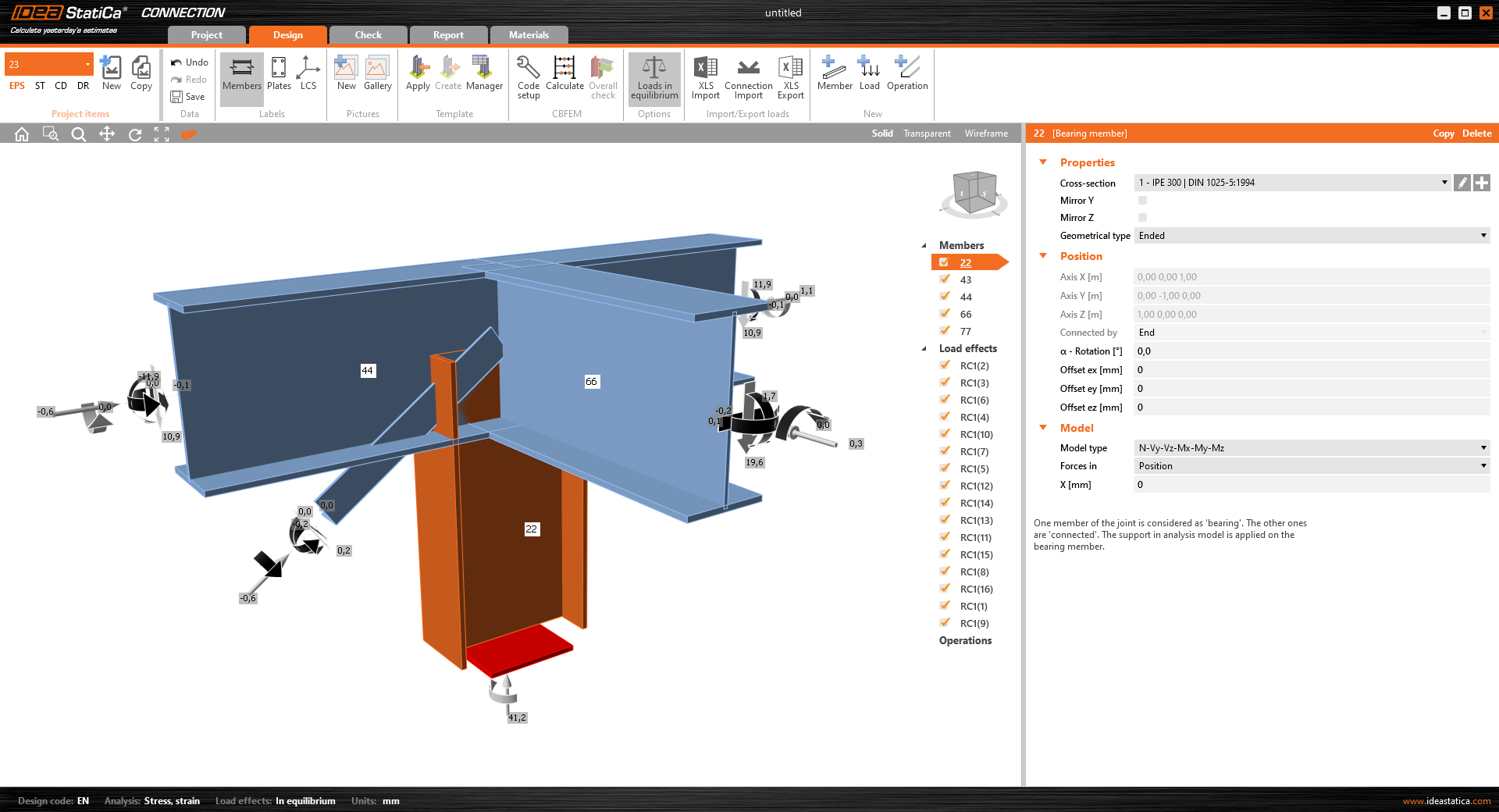
The Code-check manager opens and you can start the import process. Select one beam or column in the RFEM/RSTAB model and click Member to import it for the analysis in IDEA StatiCa Member under the EN code.

The member is added to the list together with corresponding joints and by selecting it the wireframe model together with the tab of cross-sections is displayed. In this step, you can manage the imported load cases. Leave the default settings and start configuring the connections first.

3 Design
Select node 22 in the list, click Finish, and open it in the Connection module to configure the connections by following the tutorial BIM link tutorial Connection - RFEM/RSTAB (EN) from chapter 3 on.

After that, select node 23, again click Finish, and open it to design the connections.

Instead of designing all the connections of this joint by adding the operations, take advantage of the predefined template from the provided files for download in this tutorial.
Open the template Manager and import the template into your IDEA StatiCa template database.
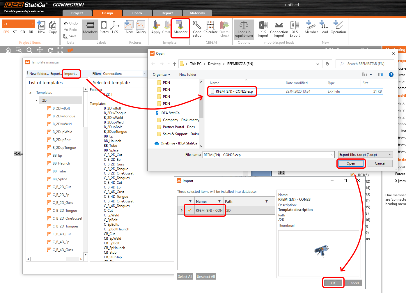
Then click Apply and select the template.

And select the default bolt assembly for this connection item.

The design template is applied and you can just click Save and close the Connection module, or you can run the analysis now and code-check the joint as well.

You have configured and designed both joints that are a part of the analyzed member. Now select the member in the list and click Finish.

And open it in the Member module.

All the data such as geometry and loads have been imported, and all connections have been already designed. The model is ready to be analyzed, but first, let's add some openings to the web of the member. Right-click on Operations in the tree menu and pick the operation Opening.

Edit the parameters of the operation, change the size and shape to N-gon (polygon with n sides) and multiply the openings number.

4 Check
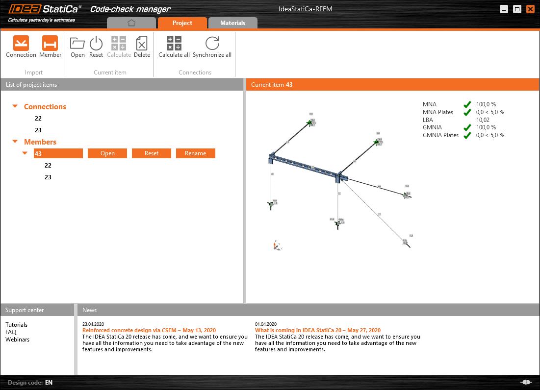
Move to the Check tab, select the MNA (Materially Nonlinear Analysis) and start the analysis by clicking Calculate in the ribbon. The analysis model is automatically generated, the calculation is performed and you can see the overall check displayed together with basic values of check results.

In the next step, switch the CBFEM analysis type to LBA (Linear buckling analysis) and run the analysis again by clicking Calculate.

When the analysis is finished, you can browse the buckling shape factors in the tab, and by selecting some, e.g. buckling shape 1, you can see it visualized in the 3D window. Selecting the Uy results display highlights the deformation trend.

Now you can calculate the GMNIA (geometrically and materially non-linear analysis with imperfections). According to EN 1993-1-1, choose the most critical buckling shape or a combination of buckling shapes and input the initial imperfection of the critical beam. In this case, buckling shape 1 is the most critical one. Switch to the GMNIA tab in the right panel and determine the imperfection of 10 mm (0,5xL/300 = 0,5*6000/300 = 10 mm) to type in as the Amplitude in column 1. Click the Calculate button, for this analysis, the calculation may take several minutes.

The member passed the code-checks with applied initial imperfections and we can browse the results such as stress distribution and internal forces diagram.

5 Report
At last, go to the tab Report. IDEA StatiCa offers a fully customizable report to be printed out or saved in .doc editable format.

You have imported a member from RFEM and designed and code-checked it according to Eurocode (EN).
6 Synchronize models
Save the project in IDEA StatiCa Member and close it. All structural details imported from RFEM/RSTAB project to IDEA StatiCa are kept on the list. The Code-check manager provides useful commands for further processing of the imported items.
To demonstrate the synchronize function, change the cross-section of the analyzed member.

Then, recalculate the project in RFEM/RSTAB and open the Code-check manager again.
Select the member from the list and click Synchronize all.
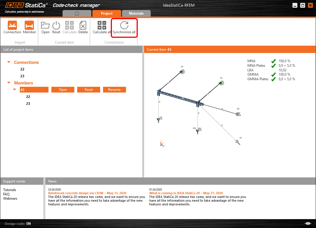
The geometry and load effects were updated and you can click Open to check the project item.

IDEA StatiCa opens and you can see the updated geometry while the design operations keep the settings.

You can check and adjust the design, recalculate and code-check the member, save and close it. Then you can continue importing and code-checking more joints or members.
Ismert korlátozások az RFEM/RSTAB esetén
Egyelőre a kapcsolat a kapcsolatok/csomópontok széles körénél működik. Kérjük azonban, vegye figyelembe a még nem támogatott funkciókat.
Korlátozás: Váll-végű vagy más típusú kúpos, illetve egyéb alakú gerincvégű gerenda exportálása nem lehetséges.
Megkerülő megoldás: A váll figyelmen kívül marad, és utólag modellezhető az IDEA StatiCa-ban.
Korlátozás: Közbenső csomópont nélküli folytonos szerkezeti elemen lévő kapcsolat exportálása nem működik.
Megkerülő megoldás: Adja hozzá a közbenső csomópontot a „Divide Member Using n Intermediate Nodes" paranccsal. A „Place/Create new nodes without dividing it" opció, amely a szerkezeti elemet folytonosként tartja meg, csak az RFEM 5-ben működik. A Checkbot alkalmazás csak „Standard" csomóponttípust ismer fel, az „On Member" vagy „On Line" csomóponttípust nem ismeri fel.
RFEM 6:

RFEM 5:

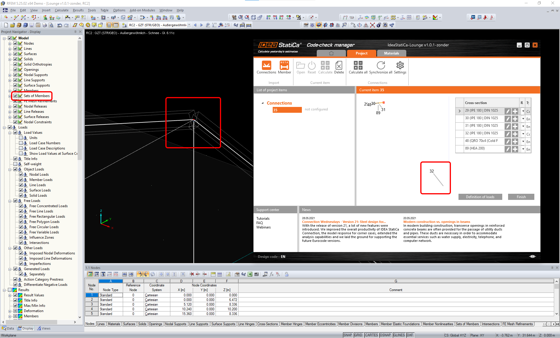
Korlátozás: A csomópont exportálása, amikor a „Sets of member" megjelenítési beállítás BE van kapcsolva, helytelen adatátvitelhez vezethet egyes szerkezeti elem keresztmetszeteinél, valamint extra szerkezeti elemek importálásához vagy hibaüzenethez.
Megkerülő megoldás: Kapcsolja KI a „Sets of member" beállítást, és ismételje meg a csomópont exportálását.
Korlátozás: Geometriai excentricitás – a csomóponti csomópont nem a középpontban van.
Megkerülő megoldás: Az RFEM/RSTAB többféle excentricitás-beviteli lehetőséget kínál. A helyi x,y,z koordinátákkal megadott excentricitás nehézségeket okoz az adatok IDEA StatiCa-ba való átalakításakor az RFEM/RSTAB koordináta-rendszer opcióinak sokfélesége miatt. Ebben az esetben kérjük, használja helyette a globális X,Y,Z koordinátás excentricitás-bevitelt.

Korlátozás: A „Joint" objektum nem támogatott az adatátvitelhez, és blokkolja a geometria importálását, valamint a kapcsolatok terheinek importálását a Checkbot-ba.
Megkerülő megoldás: Törölje a „Joint" objektumokat, számítsa újra a modellt, és importálja a kapcsolatokat.

Korlátozás: A dinamikus teherkombinációk és a dinamikus terheléseket tartalmazó teherkombinációk importálása nem támogatott.
Megkerülő megoldás: Módosítsa a dinamikus teherkombinációk definícióját az RFEM/RSTAB-ban standard teherkombinációra, az amplitúdók minden irányát külön-külön megadva, vagy adja meg a belső erőket az IDEA StatiCa-ban manuálisan, illetve XLS importálással.

Korlátozás: A nem szabványos LCS importálása nem támogatott.
Megkerülő megoldás: Csak a helyi tengelyek xyz támogatott beállításait használja.
Lásd az ábrát:
- zöld = támogatott beállítások
- piros = nem támogatott beállítások

Az RFEM5/RSTAB8 korlátozása: A különböző eredménykombinációkhoz különböző terhelési csoportokhoz rendelt teherkombinációk.
Ez azt jelenti, hogy az IDEA StatiCa-ban minden teherkombináció csak egy terhelési csoporthoz van rendelve az összes kombinációhoz, míg a Dlubal-ban egy teherkombináció különböző eredménykombinációkban különböző csoporthoz rendelhető.
Megkerülő megoldás: Az összes eredménykombinációhoz mindig rendelje a teherkombinációkat ugyanahhoz a terhelési csoporthoz. Alternatívaként pontos kombinációkat hozhat létre a „Load Combinations" eszközzel.


Az RFEM5/RSTAB8 korlátozása: Az összes azonos nevű teherkombináció hatásai (azaz az eredménykombinációban többször szerepelő esetek) összeadódnak a megfelelő együtthatóval a Checkbot-ban. Ez bizonyos teherkombinációk megduplázódásához (pl. 1*LC7 +1*LC7=2*LC7) és más teherkombinációk kieséséhez vezethet a kombinációban (pl. 1*LC9 -1*LC9= 0*LC9)!
Megkerülő megoldás: Ne használja ugyanazokat a teherkombinációkat ugyanabban az eredménykombinációban egynél többször az RFEM-ben vagy az RSTAB-ban. Ha terhelési csoportot szeretne használni az RFEM-ben és az RSTAB-ban, és ugyanazt a teherkombinációt egyszer pozitív, egyszer negatív előjellel szeretné hozzárendelni egy eredménykombinációhoz, ezt 2 független eredménykombinációval vagy teherkombinációval tegye.

Korlátozás: Az eredménykombinációkban más eredménykombinációkra való hivatkozás nem támogatott a Checkbot-ba való importáláshoz.
Megkerülő megoldás: Adjon teherkombinációkat az eredménykombinációhoz más eredménykombináció hozzáadása helyett.

Korlátozás: A belső erők nem importálódnak a Checkbot-ba, ha a megfelelő eredményértékek deaktiválva vannak az Eredménytábla-kezelőben.
Megkerülő megoldás: Nyissa meg az Eredmények → Eredménytábla-kezelő menüpontot, és aktiválja a szükséges értékeket. Győződjön meg arról, hogy a következő opciók engedélyezve vannak:
- Sorok: Szerkezeti elem kezdete, Belső pontok, Szerkezeti elem vége
- Oszlopok: Belső erők, Belső nyomatékok
