
RFEM/RSTAB BIM link for steel member design (EN) - OLD
1 How to activate the link
- Install the latest version of IDEA StatiCa
- Make sure you are using a supported version of RFEM/RSTAB
- You need to have the COM module installed in RFEM/RSTAB to create the BIM link with IDEA StatiCa.
IDEA StatiCa automatically integrates the BIM link into your CAD/CAE software during its installation. You can check the status and activate more BIM links for other software installed later in the BIM link installer.
Open IDEA StatiCa and navigate to the panel BIM and open the BIM link installer. A notification "Run as administrator" may appear, please confirm with the Yes button.
Select the software to integrate the IDEA StatiCa BIM link, click the Install button and check the status.

Note: RFEM/RSTAB BIM link provides importing only under the Eurocode (EN) standard.
2 How to use the link
First, open the source file RFEM.rf5 from the provided files for download (at the bottom of this tutorial) and open it in RFEM/RSTAB. There navigate to menu Add-on Modules then External Modules and run IDEA Statica Steel (for RFEM6/RSTAB9 use this process).

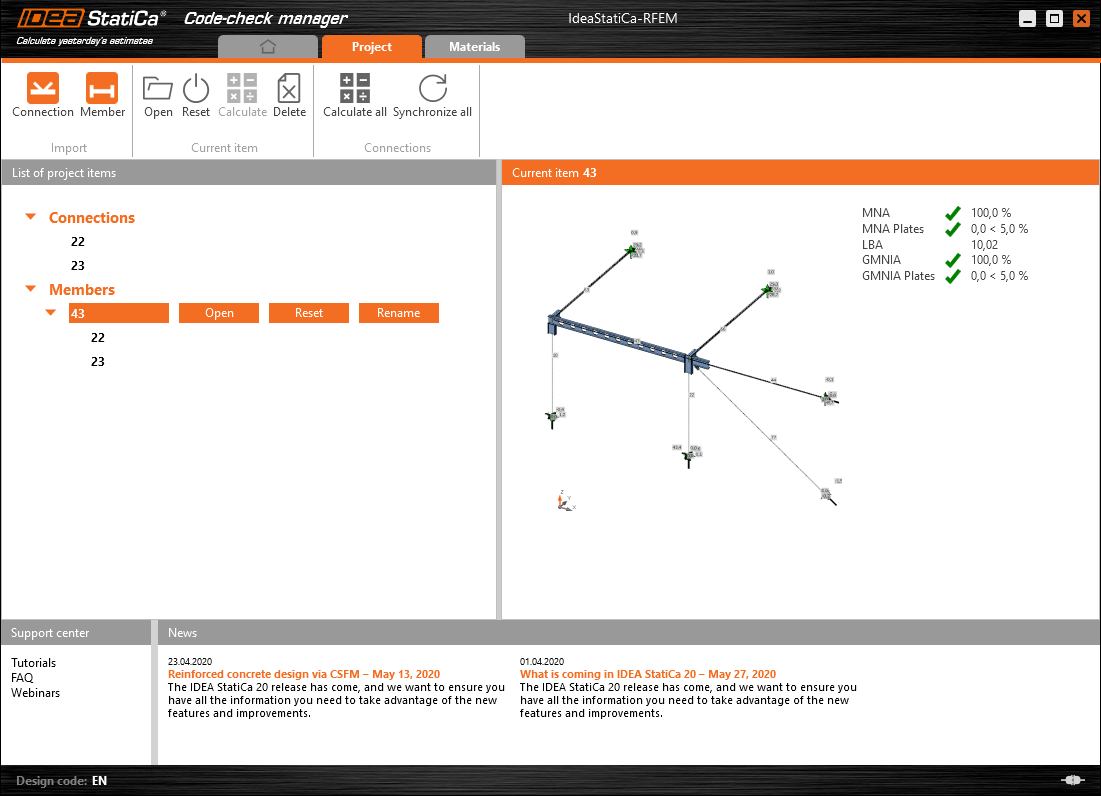
The Code-check manager opens and you can start the import process. Select one beam or column in the RFEM/RSTAB model and click Member to import it for the analysis in IDEA StatiCa Member under the EN code.

The member is added to the list together with corresponding joints and by selecting it the wireframe model together with the tab of cross-sections is displayed. In this step, you can manage the imported load cases. Leave the default settings and start configuring the connections first.

3 Design
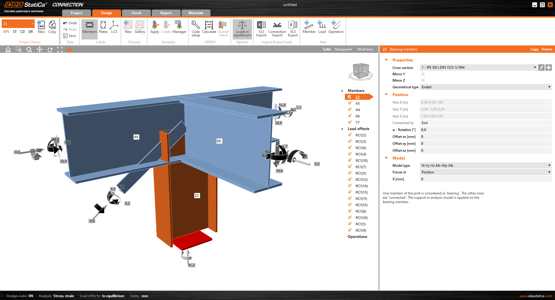
Select node 22 in the list, click Finish, and open it in the Connection module to configure the connections by following the tutorial BIM link tutorial Connection - RFEM/RSTAB (EN) from chapter 3 on.

After that, select node 23, again click Finish, and open it to design the connections.

Instead of designing all the connections of this joint by adding the operations, take advantage of the predefined template from the provided files for download in this tutorial.
Open the template Manager and import the template into your IDEA StatiCa template database.
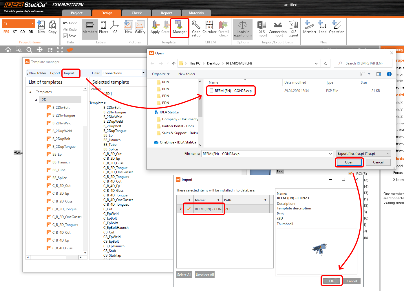
Then click Apply and select the template.

And select the default bolt assembly for this connection item.

The design template is applied and you can just click Save and close the Connection module, or you can run the analysis now and code-check the joint as well.

You have configured and designed both joints that are a part of the analyzed member. Now select the member in the list and click Finish.

And open it in the Member module.

All the data such as geometry and loads have been imported, and all connections have been already designed. The model is ready to be analyzed, but first, let's add some openings to the web of the member. Right-click on Operations in the tree menu and pick the operation Opening.

Edit the parameters of the operation, change the size and shape to N-gon (polygon with n sides) and multiply the openings number.

4 Check
Move to the Check tab, select the MNA (Materially Nonlinear Analysis) and start the analysis by clicking Calculate in the ribbon. The analysis model is automatically generated, the calculation is performed and you can see the overall check displayed together with basic values of check results.

In the next step, switch the CBFEM analysis type to LBA (Linear buckling analysis) and run the analysis again by clicking Calculate.

When the analysis is finished, you can browse the buckling shape factors in the tab, and by selecting some, e.g. buckling shape 1, you can see it visualized in the 3D window. Selecting the Uy results display highlights the deformation trend.

Now you can calculate the GMNIA (geometrically and materially non-linear analysis with imperfections). According to EN 1993-1-1, choose the most critical buckling shape or a combination of buckling shapes and input the initial imperfection of the critical beam. In this case, buckling shape 1 is the most critical one. Switch to the GMNIA tab in the right panel and determine the imperfection of 10 mm (0,5xL/300 = 0,5*6000/300 = 10 mm) to type in as the Amplitude in column 1. Click the Calculate button, for this analysis, the calculation may take several minutes.

The member passed the code-checks with applied initial imperfections and we can browse the results such as stress distribution and internal forces diagram.

5 Report
At last, go to the tab Report. IDEA StatiCa offers a fully customizable report to be printed out or saved in .doc editable format.

You have imported a member from RFEM and designed and code-checked it according to Eurocode (EN).
6 Synchronize models
Save the project in IDEA StatiCa Member and close it. All structural details imported from RFEM/RSTAB project to IDEA StatiCa are kept on the list. The Code-check manager provides useful commands for further processing of the imported items.
To demonstrate the synchronize function, change the cross-section of the analyzed member.

Then, recalculate the project in RFEM/RSTAB and open the Code-check manager again.
Select the member from the list and click Synchronize all.
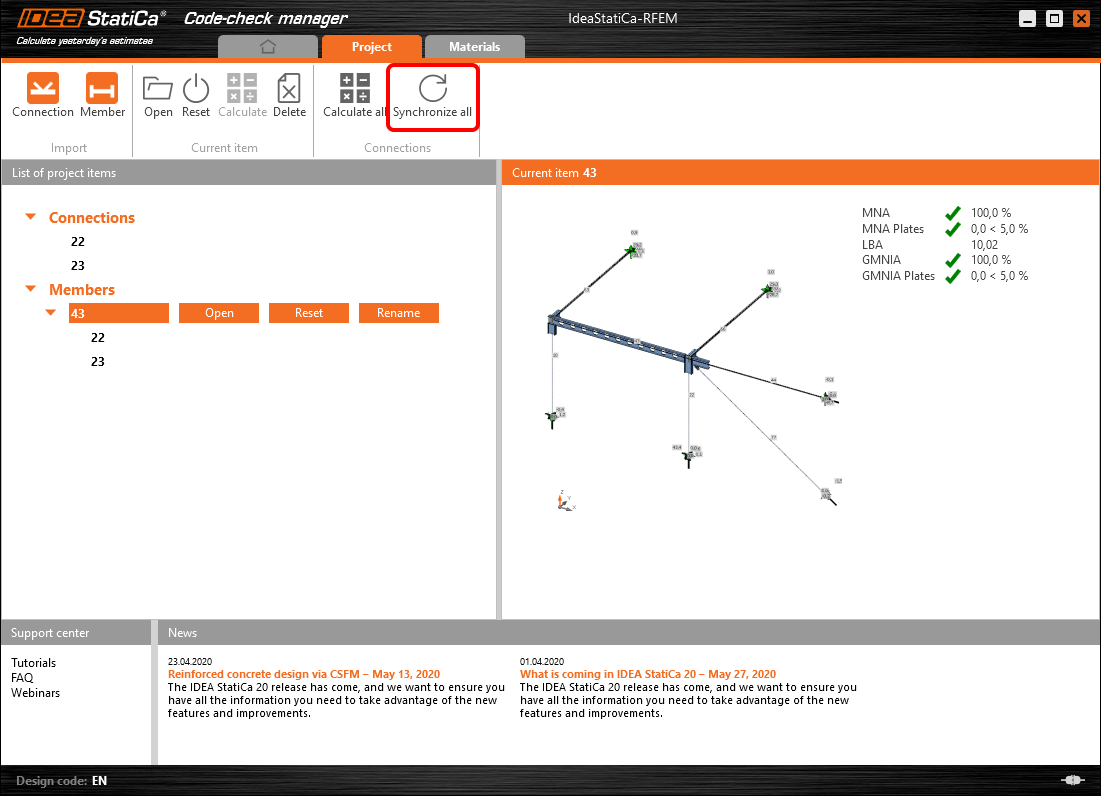
The geometry and load effects were updated and you can click Open to check the project item.

IDEA StatiCa opens and you can see the updated geometry while the design operations keep the settings.

You can check and adjust the design, recalculate and code-check the member, save and close it. Then you can continue importing and code-checking more joints or members.
Limitaciones conocidas para RFEM/RSTAB
Por ahora, el enlace funciona para una amplia variedad de uniones/juntas. Sin embargo, tenga en cuenta la funcionalidad aún no compatible.
Limitación: No es posible exportar una viga con un extremo con cartela u otro tipo de extremos de viga cónicos o de otra forma.
Solución alternativa: La cartela se ignora y puede modelarse posteriormente en IDEA StatiCa
Limitación: La exportación de una unión en un elemento continuo sin un nodo intermedio no funciona.
Solución alternativa: Añada el nodo intermedio utilizando el comando para elementos "Divide Member Using n Intermediate Nodes". La opción "Place/Create new nodes without dividing it" para mantener el elemento continuo solo funcionará en RFEM 5. La aplicación Checkbot solo puede reconocer el tipo de nodo "Standard"; los tipos de nodo "On Member" u "On Line" no serán reconocidos.
RFEM 6:

RFEM 5:

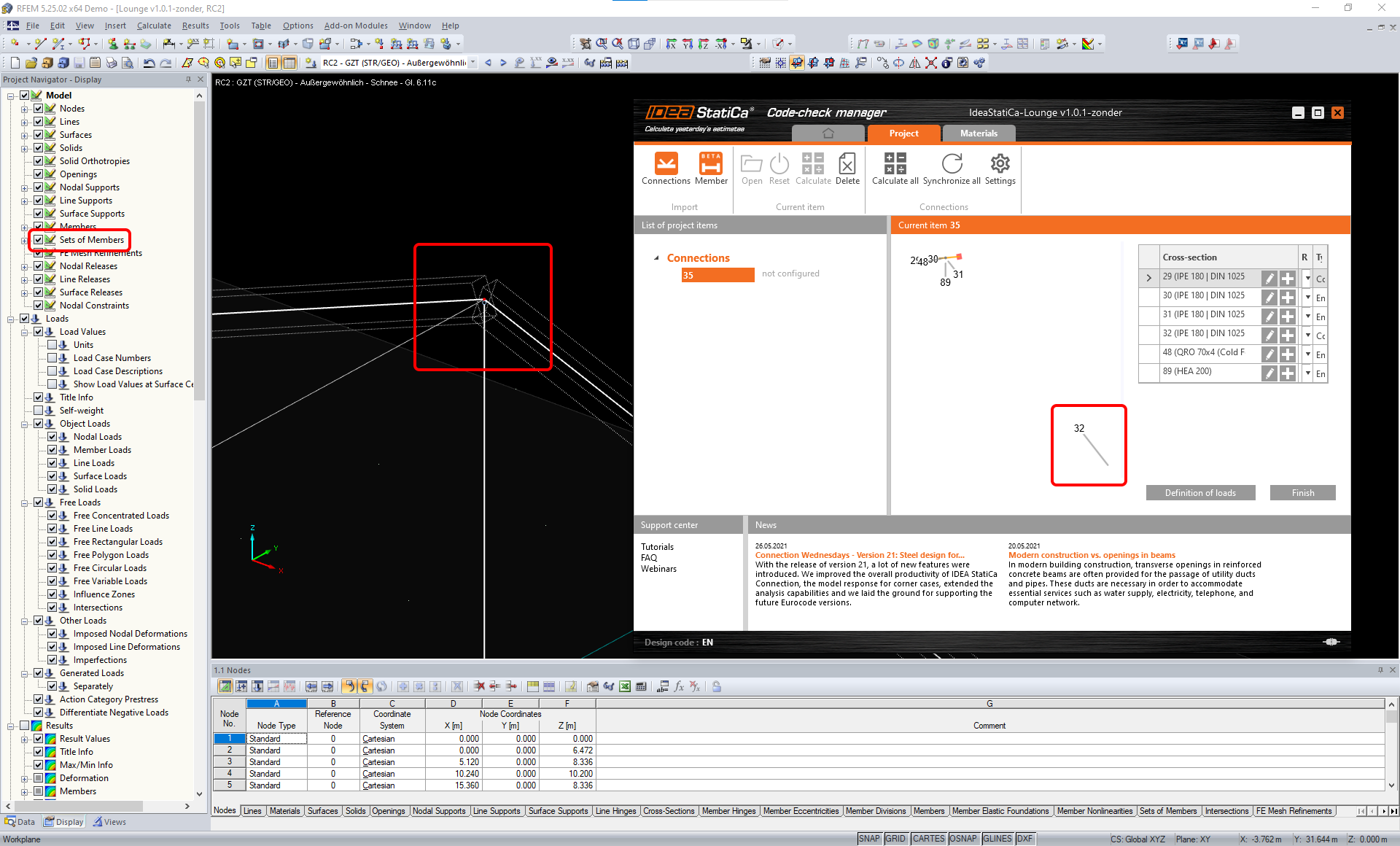
Limitación: La exportación de un nodo cuando la configuración de visualización "Sets of member" está activada puede provocar una transferencia de datos incorrecta para algunas secciones transversales de elementos e importación de elementos adicionales o un mensaje de error.
Solución alternativa: Desactive "Sets of member" y repita la exportación del nodo.
Limitación: Excentricidad geométrica: el nodo de la junta no está en el punto central.
Solución alternativa: RFEM/RSTAB ofrece varias formas de introducir excentricidades. La introducción de excentricidades mediante las coordenadas locales x,y,z genera dificultades al transformar los datos a IDEA StatiCa debido a la variedad de opciones del sistema de coordenadas en RFEM/RSTAB. En ese caso, utilice en su lugar la introducción de excentricidades mediante las coordenadas globales X,Y,Z.

Limitación: El objeto "Joint" no es compatible con la transferencia de datos y bloquea la importación de la geometría y la importación de cargas de las uniones a Checkbot.
Solución alternativa: Elimine los objetos "Joint", recalcule el modelo e importe las uniones.

Limitación: La importación de casos de carga dinámicos y combinaciones de carga que contienen cargas dinámicas no es compatible.
Solución alternativa: Cambie la definición de los casos de carga dinámicos en RFEM/RSTAB a un caso de carga estándar con cada dirección de amplitudes por separado, o introduzca los esfuerzos internos en IDEA StatiCa manualmente o mediante la importación XLS.

Limitación: La importación de LCS no estándar no es compatible.
Solución alternativa: Utilice únicamente las configuraciones compatibles de los ejes locales xyz.
Véase la figura:
- verde = configuraciones compatibles
- rojo = configuraciones no compatibles

Limitación de RFEM5/RSTAB8: Casos de carga asignados a varios grupos de carga para diferentes Combinaciones de Resultados.
Esto significa que en IDEA StatiCa cada caso de carga se asigna a un único grupo de carga para todas las combinaciones, mientras que en Dlubal un caso de carga puede asignarse a un grupo diferente en distintas Combinaciones de Resultados.
Solución alternativa: Para todas las Combinaciones de Resultados, asigne siempre los casos de carga al mismo grupo de carga. Alternativamente, puede crear combinaciones exactas utilizando la herramienta "Load Combinations".


Limitación de RFEM5/RSTAB8: Los efectos de todos los casos de carga con el mismo nombre (es decir, listados varias veces en la combinación de resultados) se suman con el coeficiente correspondiente en Checkbot. Esto puede provocar la duplicación de ciertos casos de carga (p. ej., 1*LC7 +1*LC7=2*LC7) y la cancelación de otros casos de carga en la combinación (p. ej., 1*LC9 -1*LC9= 0*LC9).
Solución alternativa: No utilice los mismos casos de carga más de una vez en la misma Combinación de Resultados en RFEM o RSTAB. Si desea utilizar el grupo de carga en RFEM y RSTAB y asignar el mismo caso de carga a una Combinación de Resultados una vez con signo positivo y otra con signo negativo, hágalo de forma diferente con 2 Combinaciones de Resultados o Combinaciones de Carga independientes.

Limitación: La referencia a otras Combinaciones de Resultados dentro de Combinaciones de Resultados no es compatible para la importación en Checkbot.
Solución alternativa: Añada casos de carga a la Combinación de Resultados en lugar de añadir otras Combinaciones de Resultados.

Limitación: Los esfuerzos internos no se importan en Checkbot si los valores de resultado correspondientes están desactivados en el Administrador de tablas de resultados.
Solución alternativa: Abra Resultados → Administrador de tablas de resultados y active los valores requeridos. Asegúrese de que las siguientes opciones estén habilitadas:
- Filas: Inicio de elementos, Puntos internos, Fin de elementos
- Columnas: Esfuerzos internos, Momentos internos
