
RFEM/RSTAB BIM link for steel member design (EN) - OLD
1 How to activate the link
- Install the latest version of IDEA StatiCa
- Make sure you are using a supported version of RFEM/RSTAB
- You need to have the COM module installed in RFEM/RSTAB to create the BIM link with IDEA StatiCa.
IDEA StatiCa automatically integrates the BIM link into your CAD/CAE software during its installation. You can check the status and activate more BIM links for other software installed later in the BIM link installer.
Open IDEA StatiCa and navigate to the panel BIM and open the BIM link installer. A notification "Run as administrator" may appear, please confirm with the Yes button.
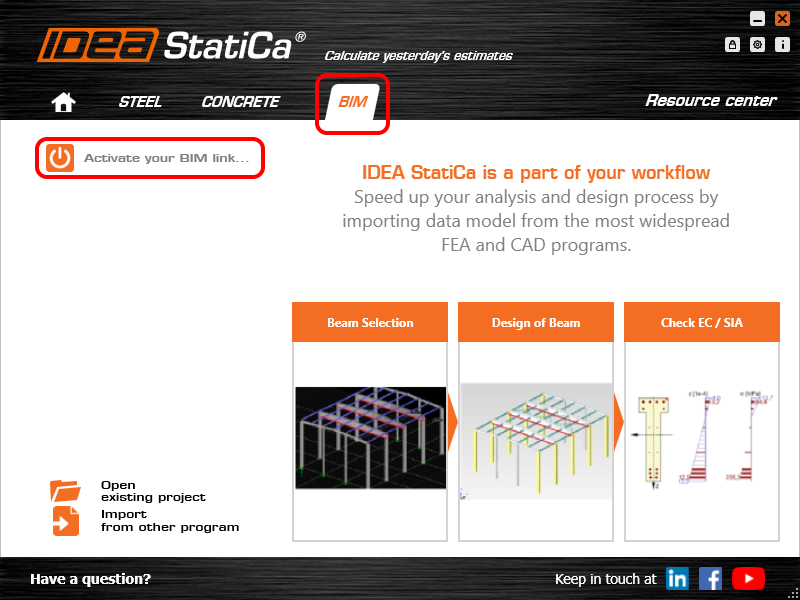
Select the software to integrate the IDEA StatiCa BIM link, click the Install button and check the status.

Note: RFEM/RSTAB BIM link provides importing only under the Eurocode (EN) standard.
2 How to use the link
First, open the source file RFEM.rf5 from the provided files for download (at the bottom of this tutorial) and open it in RFEM/RSTAB. There navigate to menu Add-on Modules then External Modules and run IDEA Statica Steel (for RFEM6/RSTAB9 use this process).

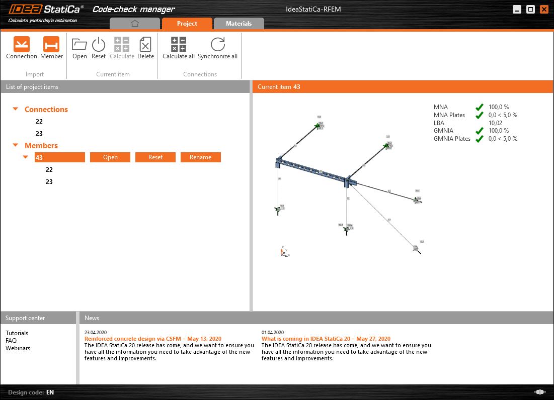
The Code-check manager opens and you can start the import process. Select one beam or column in the RFEM/RSTAB model and click Member to import it for the analysis in IDEA StatiCa Member under the EN code.

The member is added to the list together with corresponding joints and by selecting it the wireframe model together with the tab of cross-sections is displayed. In this step, you can manage the imported load cases. Leave the default settings and start configuring the connections first.

3 Design
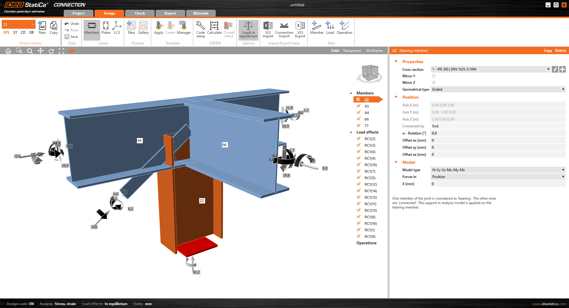
Select node 22 in the list, click Finish, and open it in the Connection module to configure the connections by following the tutorial BIM link tutorial Connection - RFEM/RSTAB (EN) from chapter 3 on.

After that, select node 23, again click Finish, and open it to design the connections.

Instead of designing all the connections of this joint by adding the operations, take advantage of the predefined template from the provided files for download in this tutorial.
Open the template Manager and import the template into your IDEA StatiCa template database.
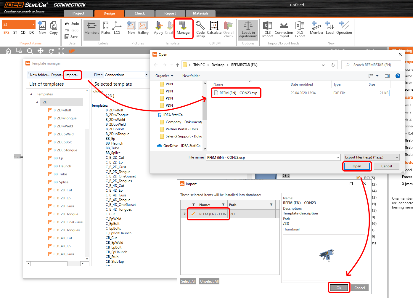
Then click Apply and select the template.

And select the default bolt assembly for this connection item.

The design template is applied and you can just click Save and close the Connection module, or you can run the analysis now and code-check the joint as well.

You have configured and designed both joints that are a part of the analyzed member. Now select the member in the list and click Finish.

And open it in the Member module.

All the data such as geometry and loads have been imported, and all connections have been already designed. The model is ready to be analyzed, but first, let's add some openings to the web of the member. Right-click on Operations in the tree menu and pick the operation Opening.

Edit the parameters of the operation, change the size and shape to N-gon (polygon with n sides) and multiply the openings number.

4 Check
Move to the Check tab, select the MNA (Materially Nonlinear Analysis) and start the analysis by clicking Calculate in the ribbon. The analysis model is automatically generated, the calculation is performed and you can see the overall check displayed together with basic values of check results.

In the next step, switch the CBFEM analysis type to LBA (Linear buckling analysis) and run the analysis again by clicking Calculate.

When the analysis is finished, you can browse the buckling shape factors in the tab, and by selecting some, e.g. buckling shape 1, you can see it visualized in the 3D window. Selecting the Uy results display highlights the deformation trend.

Now you can calculate the GMNIA (geometrically and materially non-linear analysis with imperfections). According to EN 1993-1-1, choose the most critical buckling shape or a combination of buckling shapes and input the initial imperfection of the critical beam. In this case, buckling shape 1 is the most critical one. Switch to the GMNIA tab in the right panel and determine the imperfection of 10 mm (0,5xL/300 = 0,5*6000/300 = 10 mm) to type in as the Amplitude in column 1. Click the Calculate button, for this analysis, the calculation may take several minutes.

The member passed the code-checks with applied initial imperfections and we can browse the results such as stress distribution and internal forces diagram.

5 Report
At last, go to the tab Report. IDEA StatiCa offers a fully customizable report to be printed out or saved in .doc editable format.

You have imported a member from RFEM and designed and code-checked it according to Eurocode (EN).
6 Synchronize models
Save the project in IDEA StatiCa Member and close it. All structural details imported from RFEM/RSTAB project to IDEA StatiCa are kept on the list. The Code-check manager provides useful commands for further processing of the imported items.
To demonstrate the synchronize function, change the cross-section of the analyzed member.

Then, recalculate the project in RFEM/RSTAB and open the Code-check manager again.
Select the member from the list and click Synchronize all.
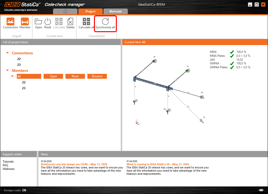
The geometry and load effects were updated and you can click Open to check the project item.

IDEA StatiCa opens and you can see the updated geometry while the design operations keep the settings.

You can check and adjust the design, recalculate and code-check the member, save and close it. Then you can continue importing and code-checking more joints or members.
Znane ograniczenia dla RFEM/RSTAB
Na chwilę obecną łącze działa dla szerokiej gamy połączeń/złączy. Należy jednak wziąć pod uwagę funkcjonalności, które nie są jeszcze obsługiwane.
Ograniczenie: Eksport elementu z końcem ze skosem lub innym rodzajem stożkowego bądź inaczej ukształtowanego końca elementu nie jest możliwy.
Obejście: Skos jest pomijany i może być modelowany później w IDEA StatiCa
Ograniczenie: Eksport połączenia na ciągłym elemencie bez węzła pośredniego nie działa.
Obejście: Dodaj węzeł pośredni za pomocą polecenia dla elementów „Divide Member Using n Intermediate Nodes". Opcja „Place/Create new nodes without dividing it" umożliwiająca zachowanie ciągłości elementu będzie działać tylko w RFEM 5. Aplikacja Checkbot rozpoznaje wyłącznie węzły typu „Standard"; typy węzłów „On Member" lub „On Line" nie będą rozpoznawane.
RFEM 6:

RFEM 5:

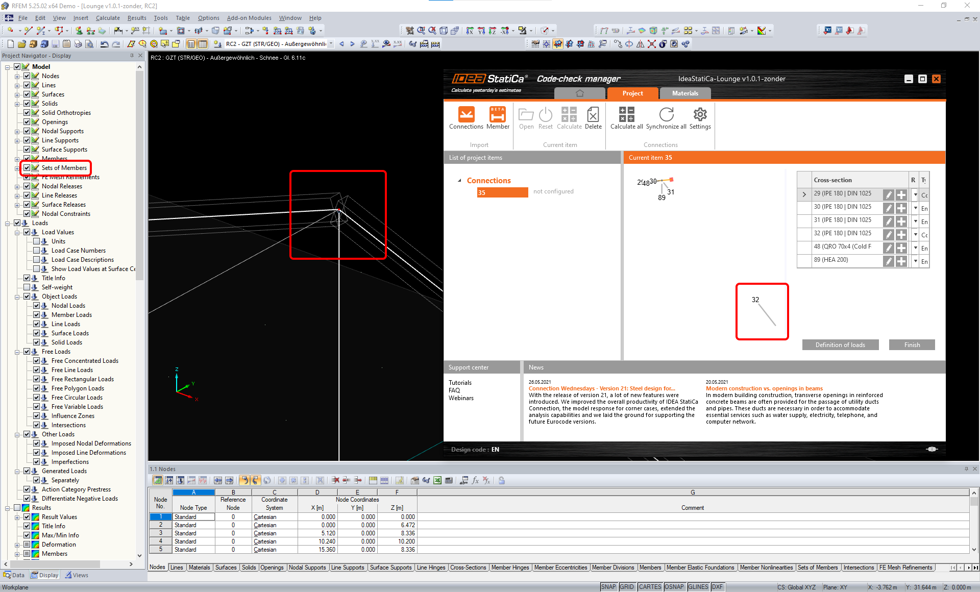
Ograniczenie: Eksport węzła przy włączonym ustawieniu wyświetlania „Sets of member" może prowadzić do nieprawidłowego transferu danych dla niektórych przekrojów elementów oraz do importu dodatkowych elementów lub wyświetlenia komunikatu o błędzie.
Obejście: Wyłącz opcję „Sets of member" i powtórz eksport węzła.
Ograniczenie: Mimośród geometryczny – węzeł złącza nie znajduje się w punkcie środkowym.
Obejście: RFEM/RSTAB oferuje wiele sposobów wprowadzania mimośrodów. Wprowadzanie mimośrodu za pomocą lokalnych współrzędnych x,y,z powoduje trudności przy transformacji danych do IDEA StatiCa ze względu na różnorodność opcji układów współrzędnych w RFEM/RSTAB. W takim przypadku należy zamiast tego użyć wprowadzania mimośrodu w globalnych współrzędnych X,Y,Z.

Ograniczenie: Obiekt „Joint" nie jest obsługiwany przy transferze danych i blokuje import geometrii oraz import obciążeń połączeń do Checkbot.
Obejście: Usuń obiekty „Joint", przelicz model i zaimportuj połączenia.

Ograniczenie: Import dynamicznych przypadków obciążeń i kombinacji obciążeń zawierających obciążenia dynamiczne nie jest obsługiwany.
Obejście: Zmień definicję dynamicznych przypadków obciążeń w RFEM/RSTAB na standardowy przypadek obciążenia z każdym kierunkiem amplitud osobno lub wprowadź siły wewnętrzne w IDEA StatiCa ręcznie albo za pomocą importu XLS.

Ograniczenie: Import niestandardowego LCS nie jest obsługiwany.
Obejście: Używaj wyłącznie obsługiwanych ustawień lokalnych osi xyz.
Patrz rysunek:
- zielony = ustawienia obsługiwane
- czerwony = ustawienia nieobsługiwane

Ograniczenie RFEM5/RSTAB8: Przypadki obciążeń przypisane do różnych grup obciążeń dla różnych kombinacji wynikowych.
Oznacza to, że w IDEA StatiCa każdy przypadek obciążenia jest przypisany tylko do jednej grupy obciążeń dla wszystkich kombinacji, podczas gdy w Dlubal przypadek obciążenia może być przypisany do innej grupy w różnych kombinacjach wynikowych.
Obejście: Dla wszystkich kombinacji wynikowych zawsze przypisuj przypadki obciążeń do tej samej grupy obciążeń. Alternatywnie możesz tworzyć dokładne kombinacje za pomocą narzędzia „Load Combinations".


Ograniczenie RFEM5/RSTAB8: Efekty wszystkich przypadków obciążeń o tej samej nazwie (tj. wymienionych wielokrotnie w kombinacji wynikowej) są sumowane z odpowiednim współczynnikiem w Checkbot. Może to prowadzić do podwojenia niektórych przypadków obciążeń (np. 1*LC7 +1*LC7=2*LC7) i zniesienia innych przypadków obciążeń w kombinacji (np. 1*LC9 -1*LC9= 0*LC9)!
Obejście: Nie używaj tych samych przypadków obciążeń w tej samej kombinacji wynikowej więcej niż raz w RFEM lub RSTAB. Jeśli chcesz użyć grupy obciążeń w RFEM i RSTAB i przypisać ten sam przypadek obciążenia do kombinacji wynikowej raz ze znakiem dodatnim i raz z ujemnym, zrób to inaczej – za pomocą 2 niezależnych kombinacji wynikowych lub kombinacji obciążeń.

Ograniczenie: Odwoływanie się do innych kombinacji wynikowych w kombinacjach wynikowych nie jest obsługiwane przy imporcie do Checkbot.
Obejście: Dodawaj przypadki obciążeń do kombinacji wynikowej zamiast dodawać inne kombinacje wynikowe.

Ograniczenie: Siły wewnętrzne nie są importowane do Checkbot, jeśli odpowiednie wartości wynikowe są dezaktywowane w Menedżerze tabel wyników (Result Table Manager).
Obejście: Otwórz Results → Result Table Manager i aktywuj wymagane wartości. Upewnij się, że następujące opcje są włączone:
- Rows: Member starts, Internal points, Member ends
- Columns: Internal forces, Internal moments
