
RFEM/RSTAB BIM link for steel member design (EN) - OLD
1 How to activate the link
- Install the latest version of IDEA StatiCa
- Make sure you are using a supported version of RFEM/RSTAB
- You need to have the COM module installed in RFEM/RSTAB to create the BIM link with IDEA StatiCa.
IDEA StatiCa automatically integrates the BIM link into your CAD/CAE software during its installation. You can check the status and activate more BIM links for other software installed later in the BIM link installer.
Open IDEA StatiCa and navigate to the panel BIM and open the BIM link installer. A notification "Run as administrator" may appear, please confirm with the Yes button.
Select the software to integrate the IDEA StatiCa BIM link, click the Install button and check the status.

Note: RFEM/RSTAB BIM link provides importing only under the Eurocode (EN) standard.
2 How to use the link
First, open the source file RFEM.rf5 from the provided files for download (at the bottom of this tutorial) and open it in RFEM/RSTAB. There navigate to menu Add-on Modules then External Modules and run IDEA Statica Steel (for RFEM6/RSTAB9 use this process).

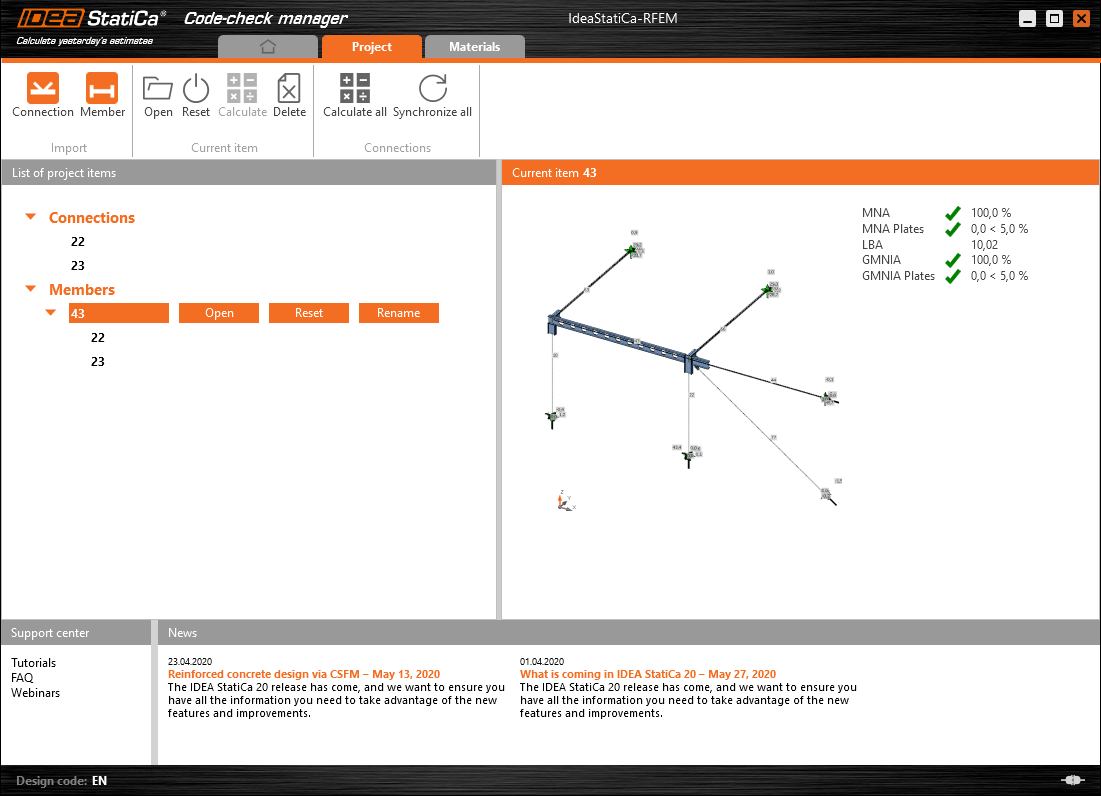
The Code-check manager opens and you can start the import process. Select one beam or column in the RFEM/RSTAB model and click Member to import it for the analysis in IDEA StatiCa Member under the EN code.

The member is added to the list together with corresponding joints and by selecting it the wireframe model together with the tab of cross-sections is displayed. In this step, you can manage the imported load cases. Leave the default settings and start configuring the connections first.

3 Design
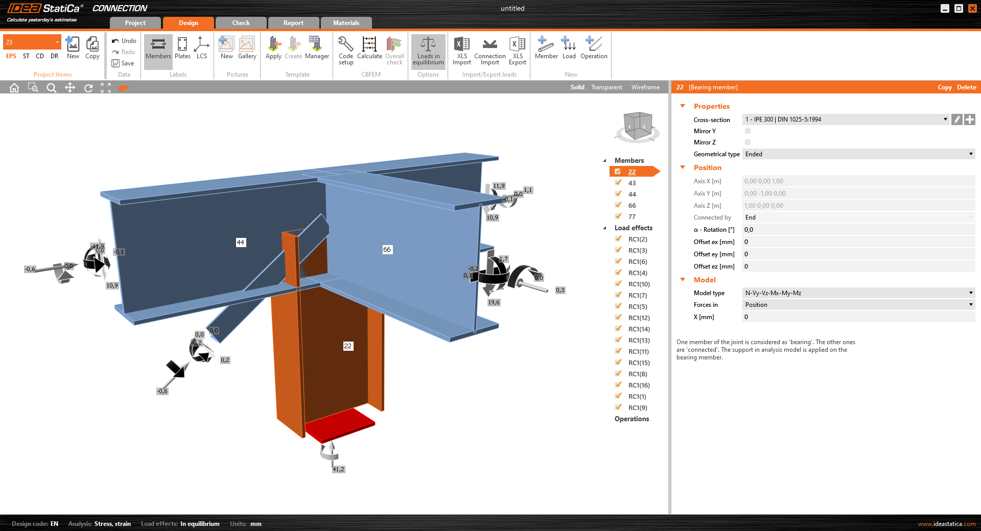
Select node 22 in the list, click Finish, and open it in the Connection module to configure the connections by following the tutorial BIM link tutorial Connection - RFEM/RSTAB (EN) from chapter 3 on.

After that, select node 23, again click Finish, and open it to design the connections.

Instead of designing all the connections of this joint by adding the operations, take advantage of the predefined template from the provided files for download in this tutorial.
Open the template Manager and import the template into your IDEA StatiCa template database.
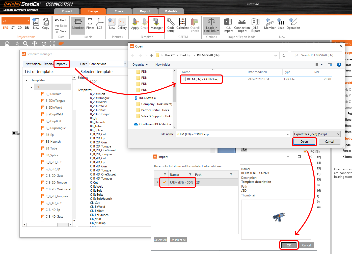
Then click Apply and select the template.

And select the default bolt assembly for this connection item.

The design template is applied and you can just click Save and close the Connection module, or you can run the analysis now and code-check the joint as well.

You have configured and designed both joints that are a part of the analyzed member. Now select the member in the list and click Finish.

And open it in the Member module.

All the data such as geometry and loads have been imported, and all connections have been already designed. The model is ready to be analyzed, but first, let's add some openings to the web of the member. Right-click on Operations in the tree menu and pick the operation Opening.

Edit the parameters of the operation, change the size and shape to N-gon (polygon with n sides) and multiply the openings number.

4 Check
Move to the Check tab, select the MNA (Materially Nonlinear Analysis) and start the analysis by clicking Calculate in the ribbon. The analysis model is automatically generated, the calculation is performed and you can see the overall check displayed together with basic values of check results.

In the next step, switch the CBFEM analysis type to LBA (Linear buckling analysis) and run the analysis again by clicking Calculate.

When the analysis is finished, you can browse the buckling shape factors in the tab, and by selecting some, e.g. buckling shape 1, you can see it visualized in the 3D window. Selecting the Uy results display highlights the deformation trend.

Now you can calculate the GMNIA (geometrically and materially non-linear analysis with imperfections). According to EN 1993-1-1, choose the most critical buckling shape or a combination of buckling shapes and input the initial imperfection of the critical beam. In this case, buckling shape 1 is the most critical one. Switch to the GMNIA tab in the right panel and determine the imperfection of 10 mm (0,5xL/300 = 0,5*6000/300 = 10 mm) to type in as the Amplitude in column 1. Click the Calculate button, for this analysis, the calculation may take several minutes.

The member passed the code-checks with applied initial imperfections and we can browse the results such as stress distribution and internal forces diagram.

5 Report
At last, go to the tab Report. IDEA StatiCa offers a fully customizable report to be printed out or saved in .doc editable format.

You have imported a member from RFEM and designed and code-checked it according to Eurocode (EN).
6 Synchronize models
Save the project in IDEA StatiCa Member and close it. All structural details imported from RFEM/RSTAB project to IDEA StatiCa are kept on the list. The Code-check manager provides useful commands for further processing of the imported items.
To demonstrate the synchronize function, change the cross-section of the analyzed member.

Then, recalculate the project in RFEM/RSTAB and open the Code-check manager again.
Select the member from the list and click Synchronize all.
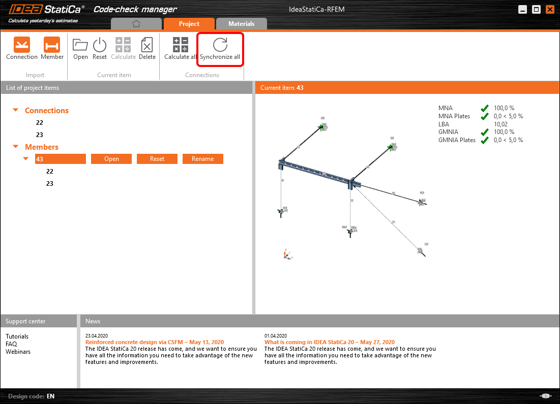
The geometry and load effects were updated and you can click Open to check the project item.

IDEA StatiCa opens and you can see the updated geometry while the design operations keep the settings.

You can check and adjust the design, recalculate and code-check the member, save and close it. Then you can continue importing and code-checking more joints or members.
RFEM/RSTAB için bilinen sınırlamalar
Şu an için bağlantı, çok çeşitli birleşimler/düğümler için çalışmaktadır. Ancak henüz desteklenmeyen işlevleri göz önünde bulundurunuz.
Sınırlama: Nervürlü (haunched) uçlu veya konik ya da başka şekilli kiriş uçlarına sahip bir kirişin dışa aktarılması mümkün değildir.
Geçici Çözüm: Nervür dikkate alınmaz ve daha sonra IDEA StatiCa'da modellenebilir.
Sınırlama: Ara düğüm olmaksızın sürekli bir eleman üzerindeki birleşimin dışa aktarılması çalışmamaktadır.
Geçici Çözüm: "Divide Member Using n Intermediate Nodes" komutuyla ara düğüm ekleyiniz. Elemanı sürekli tutmak için "Place/Create new nodes without dividing it" seçeneği yalnızca RFEM 5'te çalışacaktır. Checkbot uygulaması yalnızca "Standard" düğüm tipini tanıyabilir; "On Member" veya "On Line" düğüm tipleri tanınmayacaktır.
RFEM 6:

RFEM 5:

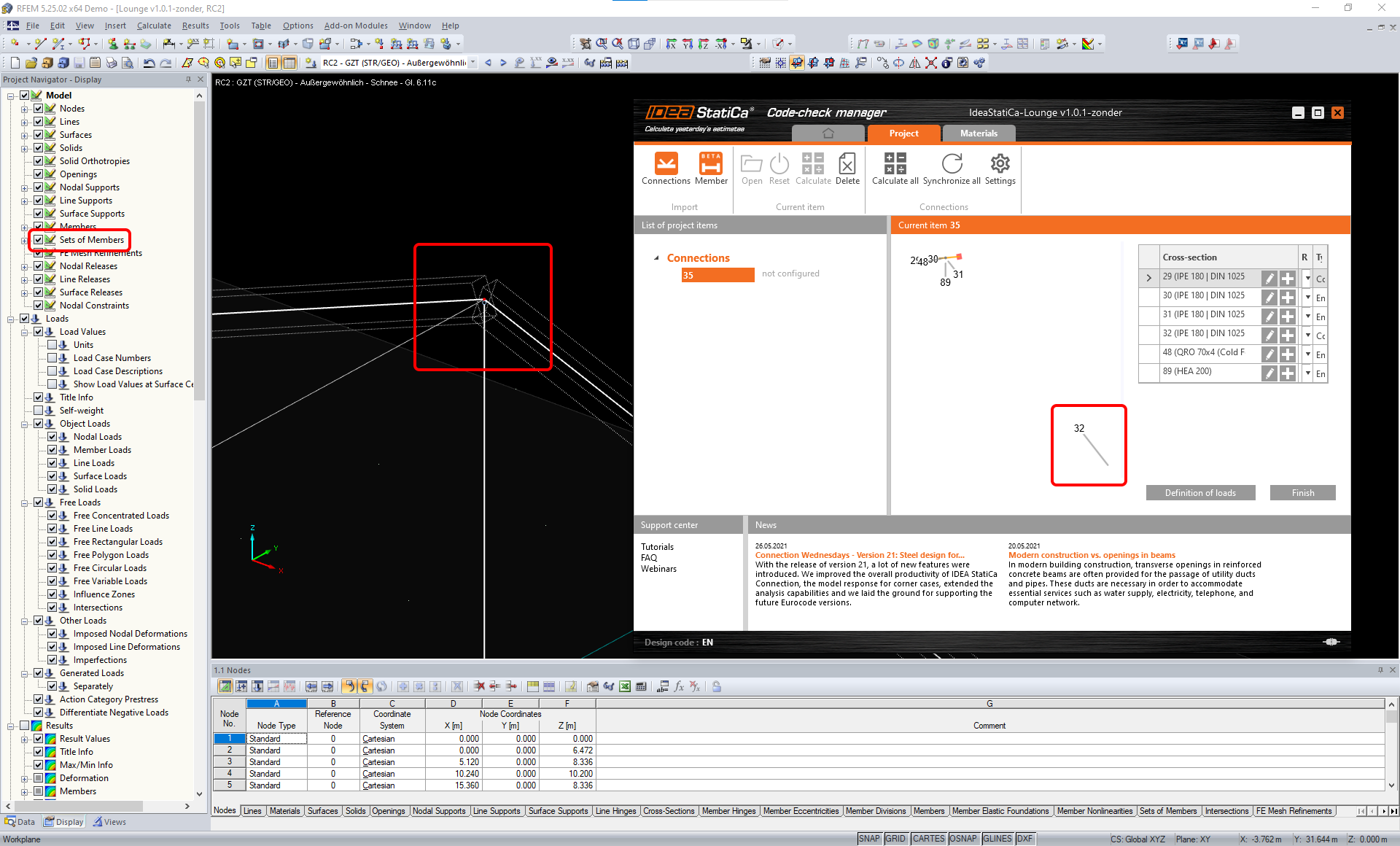
Sınırlama: "Sets of member" görüntüleme ayarı AÇIK durumdayken bir düğümün dışa aktarılması, bazı eleman kesitleri için hatalı veri aktarımına ve fazladan elemanların içe aktarılmasına ya da hata mesajına yol açabilir.
Geçici Çözüm: "Sets of member" seçeneğini KAPATIN ve düğümün dışa aktarımını tekrarlayınız.
Sınırlama: Geometrik dışmerkezlik – birleşim düğümü merkez noktasında değildir.
Geçici Çözüm: RFEM/RSTAB dışmerkezlik girişi için birden fazla yöntem sunmaktadır. Yerel x,y,z koordinatları kullanılarak yapılan dışmerkezlik girişi, RFEM/RSTAB'daki çeşitli koordinat sistemi seçenekleri nedeniyle verilerin IDEA StatiCa'ya aktarılmasında güçlük yaratmaktadır. Bu durumda lütfen bunun yerine Global X,Y,Z koordinatları ile dışmerkezlik girişini kullanınız.

Sınırlama: "Joint" nesnesi veri aktarımı için desteklenmemekte olup Checkbot'a birleşimlerin geometri ve yük içe aktarımını engellemektedir.
Geçici Çözüm: "Joint" nesnelerini siliniz, modeli yeniden hesaplayınız ve birleşimleri içe aktarınız.

Sınırlama: Dinamik yük durumlarının ve dinamik yükler içeren yük kombinasyonlarının içe aktarılması desteklenmemektedir.
Geçici Çözüm: RFEM/RSTAB'daki dinamik yük durumlarının tanımını, her genlik yönü ayrı ayrı olmak üzere standart yük durumu olarak değiştiriniz ya da iç kuvvetleri IDEA StatiCa'ya manuel olarak veya XLS içe aktarımı kullanarak giriniz.

Sınırlama: Standart dışı yerel koordinat sistemi (LCS) içe aktarımı desteklenmemektedir.
Geçici Çözüm: Yalnızca desteklenen Yerel Eksenler xyz ayarlarını kullanınız.
Şekle bakınız:
- yeşil = desteklenen ayarlar
- kırmızı = desteklenmeyen ayarlar

RFEM5/RSTAB8 Sınırlaması: Farklı Sonuç Kombinasyonları için çeşitli yük gruplarına atanmış yük durumları.
Bu durum, IDEA StatiCa'da her yük durumunun tüm kombinasyonlar için yalnızca bir yük grubuna atanması anlamına gelirken, Dlubal'da bir yük durumu farklı Sonuç Kombinasyonlarında farklı bir gruba atanabilmektedir.
Geçici Çözüm: Tüm Sonuç Kombinasyonları için yük durumlarını her zaman aynı yük grubuna atayınız. Alternatif olarak, "Load Combinations" aracını kullanarak tam kombinasyonlar oluşturabilirsiniz.


RFEM5/RSTAB8 Sınırlaması: Aynı ada sahip tüm yük durumlarının etkileri (yani sonuç kombinasyonunda birden fazla listelenenler), Checkbot'ta ilgili katsayıyla birlikte toplanmaktadır. Bu durum, belirli yük durumlarının iki katına çıkmasına (örn. 1*YD7 +1*YD7=2*YD7) ve kombinasyondaki diğer yük durumlarının birbirini sıfırlamasına yol açabilir (örn. 1*YD9 -1*YD9= 0*YD9)!
Geçici Çözüm: RFEM veya RSTAB'da aynı yük durumlarını aynı Sonuç Kombinasyonunda birden fazla kullanmayınız. RFEM ve RSTAB'da yük grubunu kullanmak ve aynı yük durumunu bir Sonuç Kombinasyonuna bir kez pozitif, bir kez negatif işaretle atamak istiyorsanız, bunu 2 bağımsız Sonuç Kombinasyonu veya Yük Kombinasyonu ile farklı şekilde yapınız.

Sınırlama: Sonuç Kombinasyonlarında diğer Sonuç Kombinasyonlarına başvurulması, Checkbot'a içe aktarım için desteklenmemektedir.
Geçici Çözüm: Başka bir Sonuç Kombinasyonu eklemek yerine, Sonuç Kombinasyonuna yük durumları ekleyiniz.

Sınırlama: İlgili sonuç değerleri Sonuç Tablosu Yöneticisi'nde devre dışı bırakılmışsa iç kuvvetler Checkbot'a aktarılmamaktadır.
Geçici Çözüm: Sonuçlar → Sonuç Tablosu Yöneticisi'ni açınız ve gerekli değerleri etkinleştiriniz. Aşağıdaki seçeneklerin etkin olduğundan emin olunuz:
- Satırlar: Eleman başlangıçları, İç noktalar, Eleman sonları
- Sütunlar: İç kuvvetler, İç momentler
