
RFEM/RSTAB BIM link for steel member design (EN) - OLD
1 How to activate the link
- Install the latest version of IDEA StatiCa
- Make sure you are using a supported version of RFEM/RSTAB
- You need to have the COM module installed in RFEM/RSTAB to create the BIM link with IDEA StatiCa.
IDEA StatiCa automatically integrates the BIM link into your CAD/CAE software during its installation. You can check the status and activate more BIM links for other software installed later in the BIM link installer.
Open IDEA StatiCa and navigate to the panel BIM and open the BIM link installer. A notification "Run as administrator" may appear, please confirm with the Yes button.
Select the software to integrate the IDEA StatiCa BIM link, click the Install button and check the status.

Note: RFEM/RSTAB BIM link provides importing only under the Eurocode (EN) standard.
2 How to use the link
First, open the source file RFEM.rf5 from the provided files for download (at the bottom of this tutorial) and open it in RFEM/RSTAB. There navigate to menu Add-on Modules then External Modules and run IDEA Statica Steel (for RFEM6/RSTAB9 use this process).

The Code-check manager opens and you can start the import process. Select one beam or column in the RFEM/RSTAB model and click Member to import it for the analysis in IDEA StatiCa Member under the EN code.

The member is added to the list together with corresponding joints and by selecting it the wireframe model together with the tab of cross-sections is displayed. In this step, you can manage the imported load cases. Leave the default settings and start configuring the connections first.

3 Design
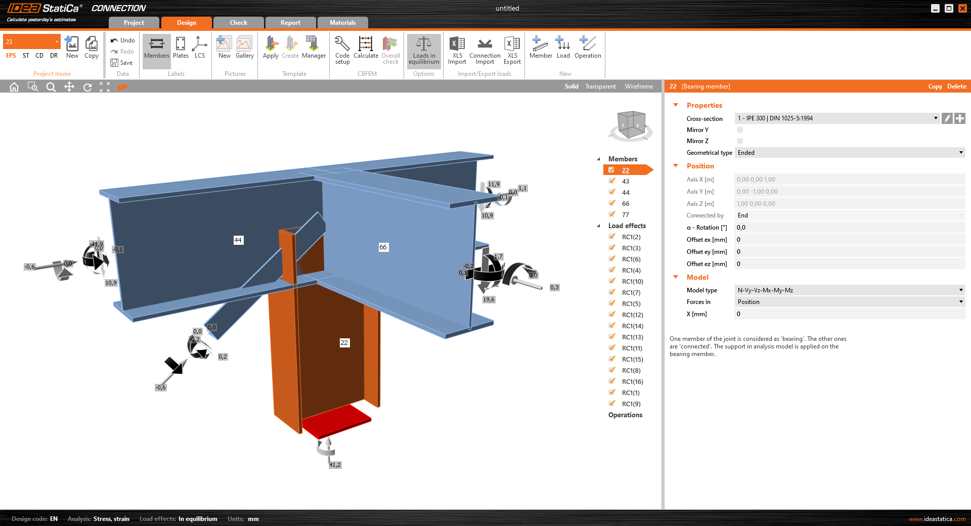
Select node 22 in the list, click Finish, and open it in the Connection module to configure the connections by following the tutorial BIM link tutorial Connection - RFEM/RSTAB (EN) from chapter 3 on.

After that, select node 23, again click Finish, and open it to design the connections.

Instead of designing all the connections of this joint by adding the operations, take advantage of the predefined template from the provided files for download in this tutorial.
Open the template Manager and import the template into your IDEA StatiCa template database.
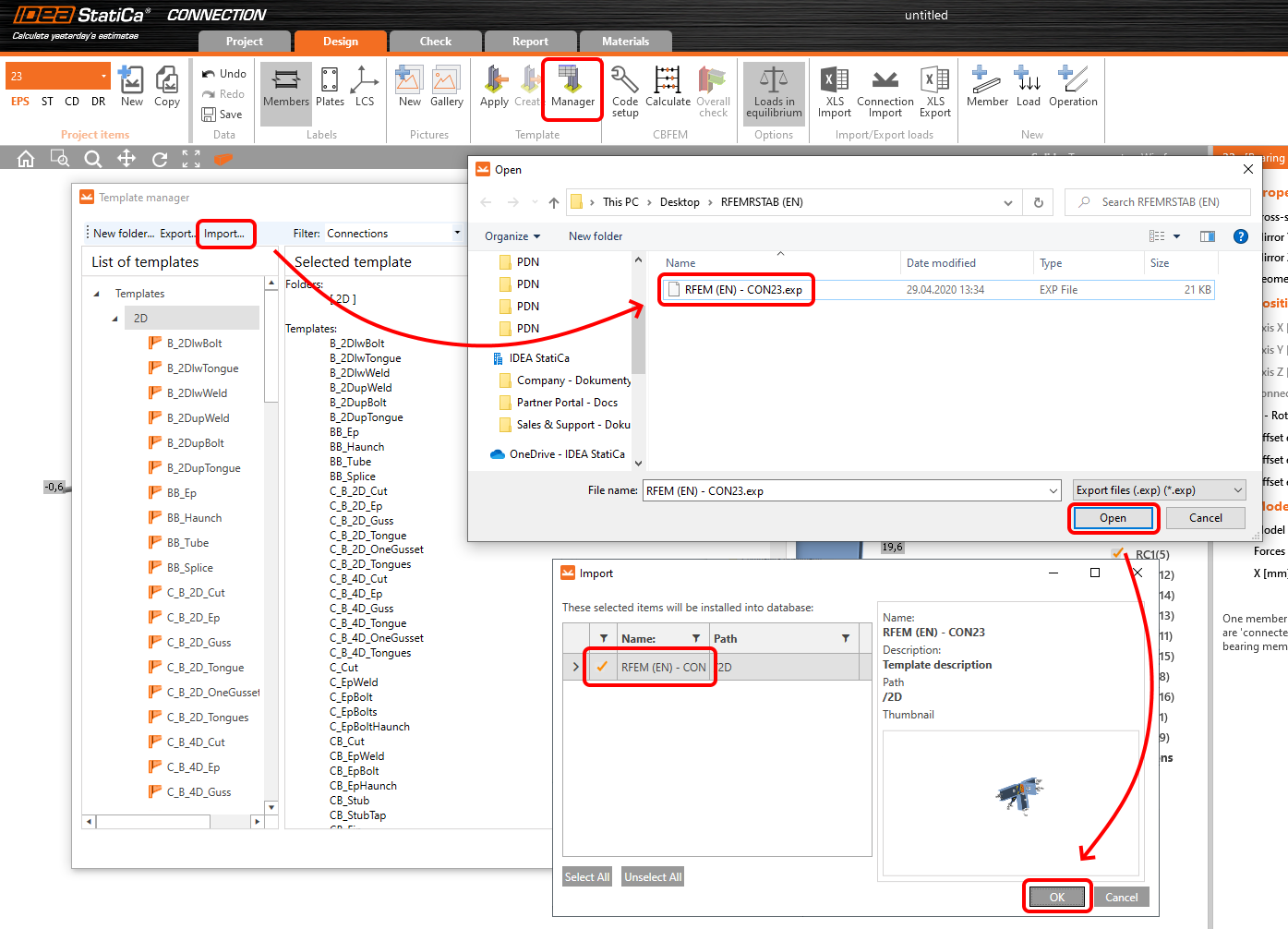
Then click Apply and select the template.

And select the default bolt assembly for this connection item.

The design template is applied and you can just click Save and close the Connection module, or you can run the analysis now and code-check the joint as well.

You have configured and designed both joints that are a part of the analyzed member. Now select the member in the list and click Finish.

And open it in the Member module.

All the data such as geometry and loads have been imported, and all connections have been already designed. The model is ready to be analyzed, but first, let's add some openings to the web of the member. Right-click on Operations in the tree menu and pick the operation Opening.

Edit the parameters of the operation, change the size and shape to N-gon (polygon with n sides) and multiply the openings number.

4 Check
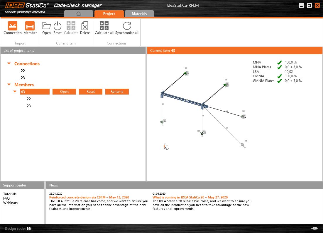
Move to the Check tab, select the MNA (Materially Nonlinear Analysis) and start the analysis by clicking Calculate in the ribbon. The analysis model is automatically generated, the calculation is performed and you can see the overall check displayed together with basic values of check results.

In the next step, switch the CBFEM analysis type to LBA (Linear buckling analysis) and run the analysis again by clicking Calculate.

When the analysis is finished, you can browse the buckling shape factors in the tab, and by selecting some, e.g. buckling shape 1, you can see it visualized in the 3D window. Selecting the Uy results display highlights the deformation trend.

Now you can calculate the GMNIA (geometrically and materially non-linear analysis with imperfections). According to EN 1993-1-1, choose the most critical buckling shape or a combination of buckling shapes and input the initial imperfection of the critical beam. In this case, buckling shape 1 is the most critical one. Switch to the GMNIA tab in the right panel and determine the imperfection of 10 mm (0,5xL/300 = 0,5*6000/300 = 10 mm) to type in as the Amplitude in column 1. Click the Calculate button, for this analysis, the calculation may take several minutes.

The member passed the code-checks with applied initial imperfections and we can browse the results such as stress distribution and internal forces diagram.

5 Report
At last, go to the tab Report. IDEA StatiCa offers a fully customizable report to be printed out or saved in .doc editable format.

You have imported a member from RFEM and designed and code-checked it according to Eurocode (EN).
6 Synchronize models
Save the project in IDEA StatiCa Member and close it. All structural details imported from RFEM/RSTAB project to IDEA StatiCa are kept on the list. The Code-check manager provides useful commands for further processing of the imported items.
To demonstrate the synchronize function, change the cross-section of the analyzed member.

Then, recalculate the project in RFEM/RSTAB and open the Code-check manager again.
Select the member from the list and click Synchronize all.
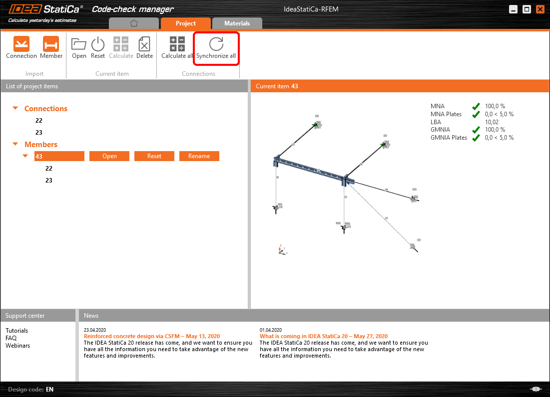
The geometry and load effects were updated and you can click Open to check the project item.

IDEA StatiCa opens and you can see the updated geometry while the design operations keep the settings.

You can check and adjust the design, recalculate and code-check the member, save and close it. Then you can continue importing and code-checking more joints or members.
Limitări cunoscute pentru RFEM/RSTAB
Deocamdată, legătura funcționează pentru o gamă largă de îmbinări/rosturi. Cu toate acestea, vă rugăm să luați în considerare funcționalitățile care nu sunt încă suportate.
Limitare: Exportul unui element cu capăt în vută sau cu alt tip de capăt conic sau de altă formă nu este posibil.
Soluție alternativă: Vuta este ignorată și poate fi modelată ulterior în IDEA StatiCa
Limitare: Exportul unei îmbinări pe un element continuu fără nod intermediar nu funcționează.
Soluție alternativă: Adăugați nodul intermediar folosind comanda pentru elemente „Divide Member Using n Intermediate Nodes". Opțiunea „Place/Create new nodes without dividing it" pentru a păstra elementul continuu va funcționa doar în RFEM 5. Aplicația Checkbot poate recunoaște doar tipul de nod „Standard"; tipurile de nod „On Member" sau „On Line" nu vor fi recunoscute.
RFEM 6:

RFEM 5:

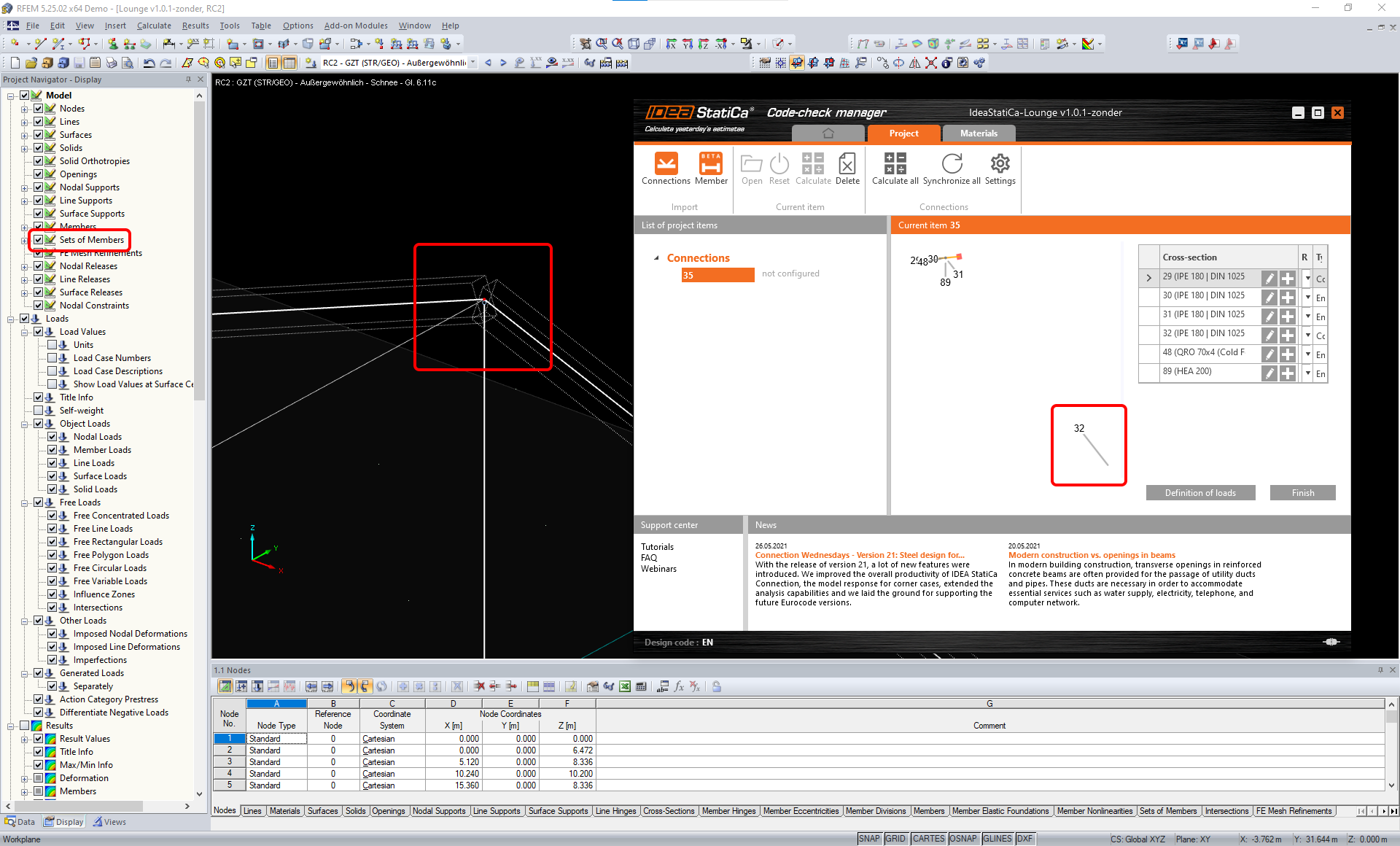
Limitare: Exportul unui nod atunci când setarea de afișare „Sets of member" este activată poate duce la transfer incorect de date pentru unele secțiuni transversale ale elementelor și la importul de elemente suplimentare sau la un mesaj de eroare.
Soluție alternativă: Dezactivați „Sets of member" și repetați exportul nodului.
Limitare: Excentricitate geometrică – nodul îmbinării nu se află în punctul central.
Soluție alternativă: RFEM/RSTAB oferă mai multe modalități de introducere a excentricităților. Introducerea excentricității folosind coordonatele locale x,y,z cauzează dificultăți la transformarea datelor în IDEA StatiCa din cauza varietății opțiunilor de sistem de coordonate din RFEM/RSTAB. În acest caz, utilizați în schimb introducerea excentricității prin coordonatele globale X,Y,Z.

Limitare: Obiectul „Joint" nu este suportat pentru transferul de date și blochează importul geometriei și al încărcărilor îmbinărilor în Checkbot.
Soluție alternativă: Ștergeți obiectele „Joint", recalculați modelul și importați îmbinările.

Limitare: Importul cazurilor de încărcare dinamică și al combinațiilor de încărcări care conțin încărcări dinamice nu este suportat.
Soluție alternativă: Modificați definiția cazurilor de încărcare dinamică în RFEM/RSTAB la caz de încărcare standard cu fiecare direcție a amplitudinilor separat, sau introduceți forțele interioare în IDEA StatiCa manual sau folosind importul XLS.

Limitare: Importul sistemelor de axe locale (LCS) nestandard nu este suportat.
Soluție alternativă: Utilizați doar setările suportate ale axelor locale xyz.
Consultați figura:
- verde = setări suportate
- roșu = setări nesuportate

Limitare RFEM5/RSTAB8: Cazuri de încărcare atribuite unor grupuri de încărcare diferite pentru diferite Combinații de Rezultate.
Aceasta înseamnă că în IDEA StatiCa fiecare caz de încărcare este atribuit unui singur grup de încărcare pentru toate combinațiile, în timp ce în Dlubal un caz de încărcare poate fi atribuit unui grup diferit în diferite Combinații de Rezultate.
Soluție alternativă: Pentru toate Combinațiile de Rezultate, atribuiți întotdeauna cazurile de încărcare aceluiași grup de încărcare. Alternativ, puteți crea combinații exacte folosind instrumentul „Load Combinations".


Limitare RFEM5/RSTAB8: Efectele tuturor cazurilor de încărcare cu același nume (adică listate de mai multe ori în combinația de rezultate) sunt adunate împreună cu coeficientul corespunzător în Checkbot. Aceasta poate duce la dublarea anumitor cazuri de încărcare (ex. 1*LC7 +1*LC7=2*LC7) și la anularea altor cazuri de încărcare în combinație (ex. 1*LC9 -1*LC9= 0*LC9)!
Soluție alternativă: Nu utilizați aceleași cazuri de încărcare în aceeași Combinație de Rezultate de mai mult de o dată în RFEM sau RSTAB. Dacă doriți să utilizați grupul de încărcare în RFEM și RSTAB și să atribuiți același caz de încărcare unei Combinații de Rezultate o dată cu semn pozitiv și o dată cu semn negativ, procedați diferit cu 2 Combinații de Rezultate sau Combinații de Încărcări independente.

Limitare: Referențierea altor Combinații de Rezultate în Combinații de Rezultate nu este suportată pentru importul în Checkbot.
Soluție alternativă: Adăugați cazuri de încărcare în Combinația de Rezultate în loc să adăugați alte Combinații de Rezultate.

Limitare: Forțele interioare nu sunt importate în Checkbot dacă valorile de rezultat corespunzătoare sunt dezactivate în Result Table Manager.
Soluție alternativă: Deschideți Results → Result Table Manager și activați valorile necesare. Asigurați-vă că următoarele opțiuni sunt activate:
- Rânduri: Member starts, Internal points, Member ends
- Coloane: Internal forces, Internal moments
