Different ways to define load effects
To define the loads, you can use one of these five options:
- Manual input into the table
- Manual input from a spreadsheet
- Automatic import using the BIM link (IDEA StatiCa Checkbot)
- Load transfer from one Connection project to another
- Percentage load based on the capacity of the cross-section
Now, let's have a look at each of the options on the list.
1. Manual input into the table
This is the basic and straightforward procedure: In the table of loads, you can load members by the set of six internal forces.
Based on the selected "Loads in equilibrium" option, the table of unbalanced forces is displayed at the bottom. (Note: When the option is OFF, you cannot apply load on the supported member. For more, go to Equilibrium and supporting member.)
Different actions are available in the top ribbon, above the load table, or in the right-mouse-button menu. You can define several load cases, copy or delete the existing ones or unselect some load cases for the analysis (these will not be evaluated).
To display the diagram of the bending moment on the selected member, switch the view mode to Wireframe (right top corner of the 3D scene) and select the member in the load table. The red load in the scene represents the load in the support (reactions).
Based on the selected model type, the corresponding cells in the load table are "locked" (preventing input). See more in the How to model one bolt connection (Model type) article.
To switch the units, see How to change units in IDEA StatiCa Connection.
Make sure you set the forces in the correct position together with the corresponding members' model types. Read the How to define correct load position (Forces in) article to understand the problem.
2. Manual input from a spreadsheet
To save time or transfer the load from another source file (it can be your global analysis model or just another IDEA StatiCa Connection model), there is an option to input the load values of the table in bulk from a spreadsheet. Use the XLS Import button in the top ribbon.
In the figure, the Excel table consists of three load cases. Simply copy + paste the values (CRTL+C and CTRL+V).
The values are automatically divided into three load cases. Ensure that the order of lines you are transferring corresponds exactly to the order of members in the Connection table of loads. You can rearrange the table using the arrows on the right. To avoid the first empty load case, use the Replace existing loads option.
Once you confirm by OK, three load cases are created. The zero values in the table of unbalanced forces confirm that the import was done correctly. See also How to import load effects from Excel sheet.
For a large set of load effects, consider using the Load Extreme Selection function.
To transfer the load from one IDEA StatiCa Connection model to another, you can also export the values into a table using the XLS Export button in the top ribbon. The load effects are saved as a CSV file. Nevertheless, there is also an easier way described in section 4 (Load transfer from one Connection project to another).
3. Automatic import using the BIM link (IDEA StatiCa Checkbot)
BIM workflow is the essential functionality of IDEA StatiCa Connection. By using the BIM link, internal forces from all load combinations and load cases are imported at once. To make an easy and smooth transfer of not only the loads but also all the members and cross-sections, we have developed IDEA StatiCa Checkbot, an application enabling IDEA StatiCa Connection to seamlessly incorporate itself into the overall BIM process.
Please see the full functionality of IDEA StatiCa Checkbot in the dedicated article or learn how to use it together with your FEA/CAD application in one of many of our tutorials.
If you are not sure whether we are linked to the application you work with, please visit our Supported integrations site. Read more about the topic also in the BIM – The answer to all our (structural engineering) prayers? blogpost.
The unbalanced forces when importing the load using the BIM link are discussed in the Unbalanced forces from BIM link import article.
4. Load transfer from one Connection project to another
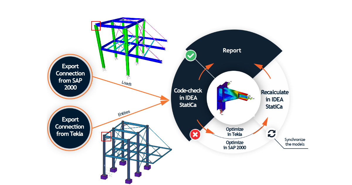
This is another option for transferring the load from one IDEA StatiCa Connection model to another. This may be useful, especially when you have a CAD model with designed connections and a structural model in an FEA program. In such a case, you can merge the loads from the FEA-exported connection model with your CAD-exported connection model and you are ready to run the analysis.
Press the Connection Import button on the top ribbon.
Then select the .ideacon file you want to import the load from.
All the load cases are transferred to your new connection model.
See the recording of our Tackling IDEA StatiCa Connection - BIM links webinar, where the load transfer from one .ideacon file to another by the Connection Import function is explained to combine the Tekla and SAP2000 models.
The combined workflow is also described in our How to combine Tekla Structures and SAP2000 tutorial.
5. Percentage load based on the capacity of the cross-section
This is a simple option for inputting the load effects: The members can be loaded by a defined percentage of the capacity of its cross-section. The setting of loads as a percentage of cross-section capacity is meant mainly as a simple tool. Setting loads in equilibrium is preferred.
Read more about this feature in the dedicated Percentage loading article.


