
SCIA Engineer BIM link for connection design (old)
1 How to activate the link
- Download and install (as administrator) the latest version of IDEA StatiCa
- Make sure that you are using the supported version of SCIA Engineer
IDEA StatiCa automatically integrates the BIM link into your CAD/CAE software during its installation. You can check the status and activate more BIM links for later installed software in the BIM link installer.
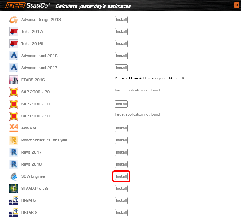
Open IDEA StatiCa and navigate to the panel BIM and open the BIM link installer. A notification "Run as administrator" may appear, please confirm with the Yes button.

Select the software to integrate the IDEA StatiCa BIM link, click the Install button and check the Installed status.
2 How to use the link
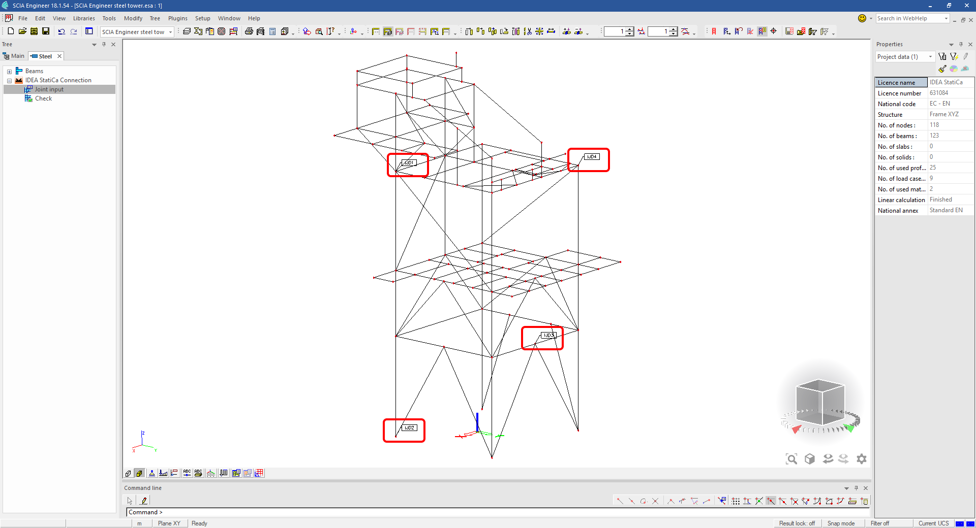
Download the attached project, open it in SCIA Engineer, and run the linear analysis to get the internal forces over the structure.
In the Main menu, go to the tab Steel.

Go to the IDEA StatiCa Connection menu. Add a joint to this SCIA Engineer project list of joints by selecting the members of a joint, then by clicking on Joint input and typing the name of it (name of the IDEA StatiCa Connection project file) and OK.

Open the command Check, run the command Export to IDEA Statica Connection in the Actions menu, and select the joint sign in the workspace.

Application IDEA StatiCa Connection opens and you can design connections of the joint.
3 Design
Joint geometry and load effects have been imported, you can start designing.

You will define a set of manufacturing operations to model connections between members. Hide the Load effects tree and right-click on Operations to add a new operation Cut.


In the next step add another manufacturing operation Endplate and modify its parameters.


Then add a Connecting plate operation and set its parameters for the appropriate member.


Right-click on the tongue plate, open the plate Editor and reshape the Tongue by adding an operation Rounding.


Next, you will again right-click on the gusset plate and in the Editor reshape the Gusset plate by adding a Bevel operation.


Now you can add a Stiffener operation and modify its properties.


Add another Cut operation for the upper member.


Again, use the Cut operation for the diagonals.


Copy the last cut operation and set it for the other diagonal.


In the next step add a Stiffener to the main column.


Finish the design by adding a Fin plate operation to connect the last member.


4 Check
You can start the analysis by clicking Calculate in the ribbon. The analysis model is automatically generated, the calculation is performed for all the load cases and you can see the Overall check displayed together with basic values of check results.

Go to the display tab Check and there activate Equivalent stress, Bolt forces, Mesh and Deformed and change the deformation scale in the ribbon to get a full picture of what is happening in the joint.

By default, you can see the For extreme results envelope of all the load effects, so the most unfavorable results are displayed all together. If you click on any item (e.g. the fin plate), it shows you which load effect is the most unfavorable for it in the ribbon.

You can also display and browse results for each load effect separately by changing the For the extreme option to For current in the ribbon.

5 Report
At last, go to the tab Report. IDEA StatiCa offers a fully customizable report to print out or save in an editable format.


You have imported a joint from SCIA Engineer and designed and code-checked it according to Eurocode.
6 How to update the project
Save the project and close the application Connection. All joints exported from an SCIA Engineer project to IDEA StatiCa are kept on the list as a part of the SCIA Engineer project file for later updates.
Note: In case you need to send a simple IDEA StatiCa file, you can "save as" a copy of the opened joint model to the desired folder
Go back to the SCIA Engineer model, change the cross-section of one of the diagonals, and start the Calculation of linear analysis again.

Open again the command Check, run the command Export to IDEA StatiCa Connection in the Actions menu, and select the joint sign in the workspace.

IDEA StatiCa opens and you can see the updated geometry while the design and settings adjust to the new state.

You can adjust the design, recalculate the joint code-check and save the project in IDEA StatiCa again and continue with exporting other joints.
SCIA Engineer için bilinen sınırlamalar
Sınırlama: Doğrusal olmayan kombinasyonlar IDEA StatiCa Checkbot uygulamasına aktarılamaz.
Sınırlama: "α" kullanılarak döndürülen elemanlar SCIA Engineer'dan Checkbot'a aktarılamaz.
Geçici Çözüm: Bunun yerine "LCS Rotation" kullanarak elemanı döndürün; elemanların dönüşü doğru şekilde aktarılacaktır.

Sınırlama: SCIA Engineer'da modellenen köşe takviyeleri Checkbot'a aktarılmaz.
Geçici Çözüm: Köşe takviyeleri, IDEA StatiCa Connection'da İşlemler kullanılarak ayrıca modellenmelidir.

Sınırlama: "member system-line at" kullanılarak modellenen dışmerkezlik, 25.0 ve önceki sürümlerde aktarılmaz. 25.1.0 sürümünden itibaren bu sınırlama kaldırılmıştır ve elemanlar tanımlanan sistem ekseniyle aktarılır.
Geçici Çözüm: Dışmerkezlik, ez veya ey değeri aracılığıyla tanımlanmalıdır. Eleman sistem ekseni "Centre" olarak ayarlanmalıdır.

SCIA Engineer 21.1 sürümüyle birlikte IDEA StatiCa, SCIA Engineer ile Checkbot uygulaması arasındaki BIM bağlantısının nasıl kullanılacağına dair başka bir seçenek sunmuştur.
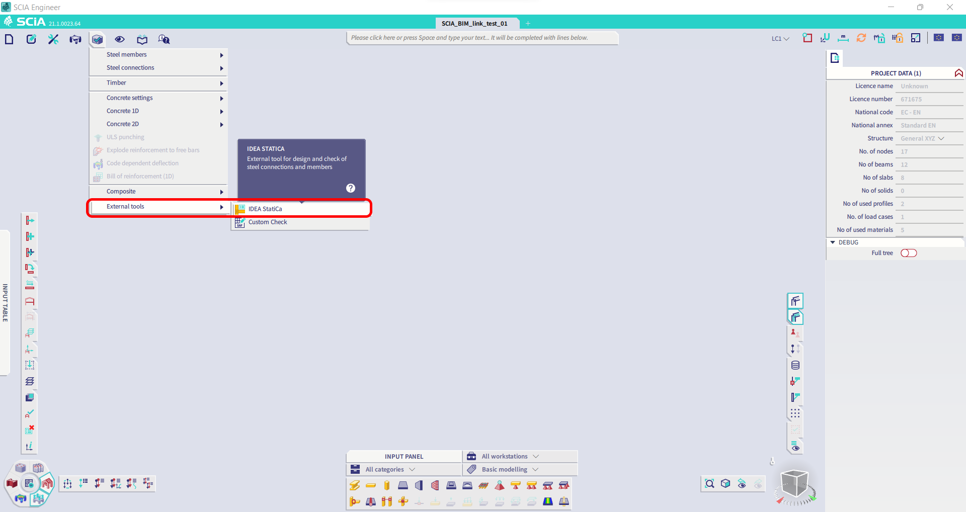
Sınırlama: Bu özellik, SCIA 21.1'in Legacy sürümüne dahil değildir.
Geçici Çözüm: SCIA 21.1'in varsayılan kullanıcı arayüzünü kullanın.
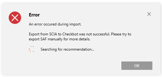
Sınırlama: SCIA, Bimlink iletişimi için kullanılan SAF dosyasını oluşturamamaktadır. Sorun, Checkbot'ta aşağıdaki hatayla ve SAF modelini doğrudan SCIA'dan dışa aktarırken aşağıdaki mesajla kendini göstermektedir.

Geçici Çözüm: Düzeltmek için aktarım yöntemi seçimini Tributary Area'dan Accurate (FEM)'e değiştirin.
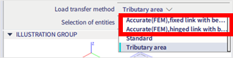
ÖNEMLİ NOT: Scia Engineer 26.0 sürümünde SAF'a dışa aktarma sorunu giderilmiş olup yukarıda gösterilen hata mesajı artık görünmemektedir.
Sınırlama: Standart kombinasyonlar IDEA StatiCa Checkbot Uygulamasına aktarılamaz.
Geçici Çözüm: SCIA Engineer'da, dışa aktarmadan önce kombinasyonları zarflara veya doğrusal kombinasyonlara parçalayın.

Sınırlama: "Standard" dışında bir LCS türüne sahip elemanlar, Checkbot'a dışa aktarmanın başarısız olmasına neden olur.
Geçici Çözüm: Checkbot'a aktarım sırasında aşağıdaki hata görüntülendiğinde:
SCIA'ya gidin ve SAF dosyasını manuel olarak dışa aktarın.
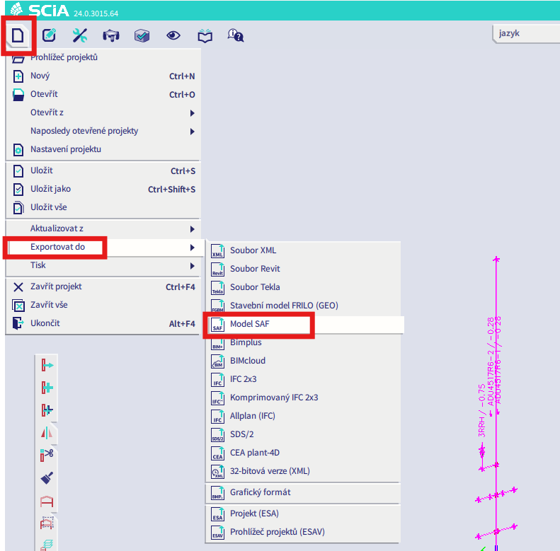
Dışa aktarma başarısız olursa "INFO" seçeneğine tıklayın; üst satırlar, "standard" dışında LCS kullanan elemanlar hakkında bilgi verir.
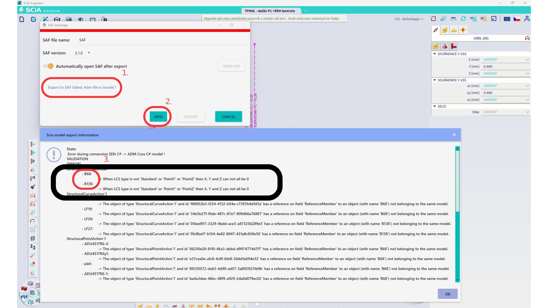
Elemanları bulun ve LCS'lerini "standard" olarak değiştirin. Yeniden hesaplayın ve BIM bağlantısını yeniden başlatın.
Sınırlama: Scia Engineer'daki, tanımlı "Master load case" içeren yük durumlarını barındıran zarf kombinasyonları, SAF dosyasındaki eksik bilgi nedeniyle IDEA StatiCa Checkbot uygulamasına aktarımdan sonra doğru şekilde birleştirilememektedir.
Geçici Çözüm: Dışa aktarmadan önce, SCIA Engineer'da tanımlı "Master load case" içeren yük durumlarını barındıran zarf kombinasyonlarını doğrusal kombinasyonlara parçalayın.

Sınırlama: Yük grubundaki Together İlişkisi, IDEA StatiCa Checkbot uygulamasına aktarımdan sonra dikkate alınmamakta ve Scia Engineer ile Checkbot arasında tutarsız iç kuvvetlere neden olmaktadır.

Geçici Çözüm: Dışa aktarmadan önce, Scia Engineer'da zarf kombinasyonlarını doğrusal kombinasyonlara parçalayın. İkinci yol ise IDEA StatiCa Connection'a doğrudan bağlantı kullanmaktır.