
SCIA Engineer BIM link for connection design (old)
1 How to activate the link
- Download and install (as administrator) the latest version of IDEA StatiCa
- Make sure that you are using the supported version of SCIA Engineer
IDEA StatiCa automatically integrates the BIM link into your CAD/CAE software during its installation. You can check the status and activate more BIM links for later installed software in the BIM link installer.
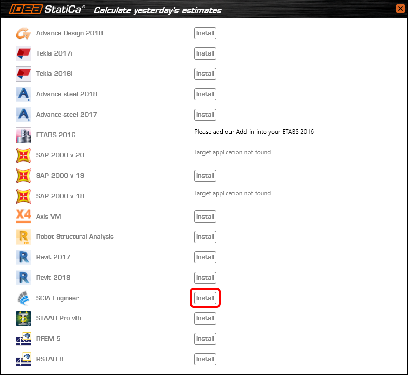
Open IDEA StatiCa and navigate to the panel BIM and open the BIM link installer. A notification "Run as administrator" may appear, please confirm with the Yes button.

Select the software to integrate the IDEA StatiCa BIM link, click the Install button and check the Installed status.
2 How to use the link
Download the attached project, open it in SCIA Engineer, and run the linear analysis to get the internal forces over the structure.
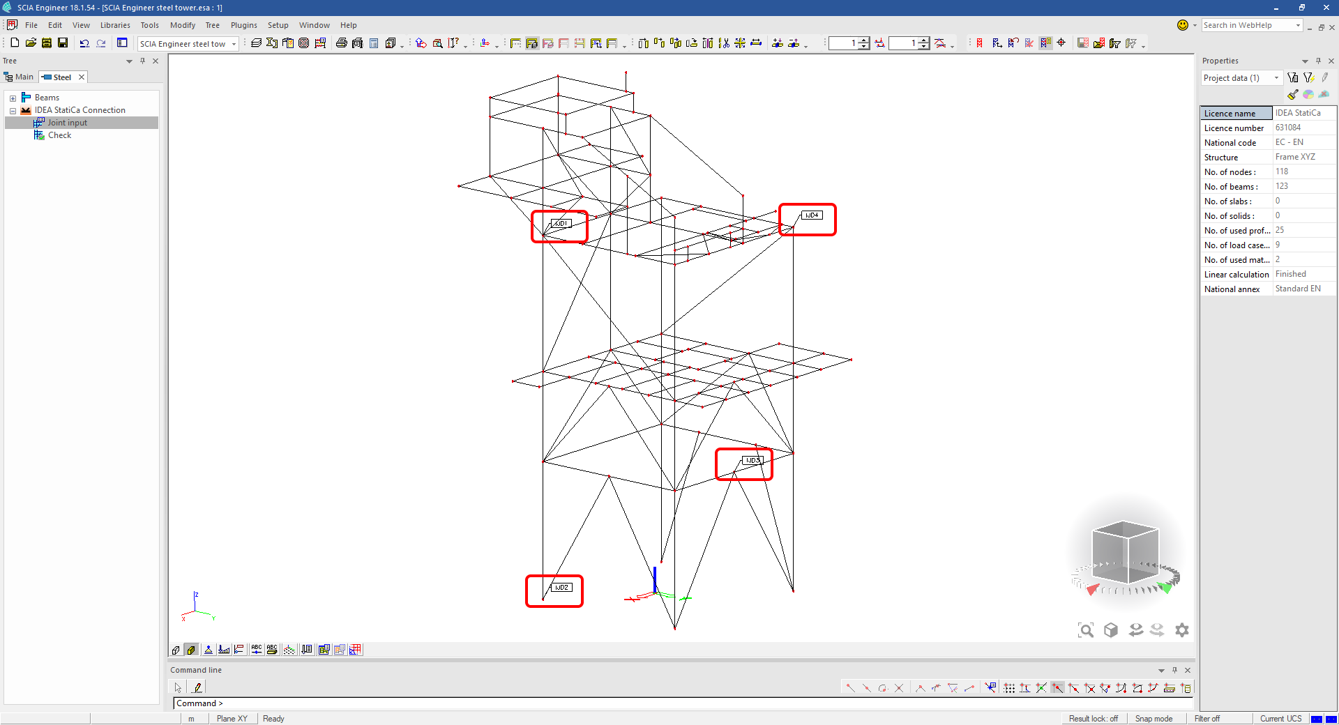
In the Main menu, go to the tab Steel.

Go to the IDEA StatiCa Connection menu. Add a joint to this SCIA Engineer project list of joints by selecting the members of a joint, then by clicking on Joint input and typing the name of it (name of the IDEA StatiCa Connection project file) and OK.

Open the command Check, run the command Export to IDEA Statica Connection in the Actions menu, and select the joint sign in the workspace.

Application IDEA StatiCa Connection opens and you can design connections of the joint.
3 Design
Joint geometry and load effects have been imported, you can start designing.

You will define a set of manufacturing operations to model connections between members. Hide the Load effects tree and right-click on Operations to add a new operation Cut.


In the next step add another manufacturing operation Endplate and modify its parameters.


Then add a Connecting plate operation and set its parameters for the appropriate member.


Right-click on the tongue plate, open the plate Editor and reshape the Tongue by adding an operation Rounding.


Next, you will again right-click on the gusset plate and in the Editor reshape the Gusset plate by adding a Bevel operation.


Now you can add a Stiffener operation and modify its properties.


Add another Cut operation for the upper member.


Again, use the Cut operation for the diagonals.


Copy the last cut operation and set it for the other diagonal.


In the next step add a Stiffener to the main column.


Finish the design by adding a Fin plate operation to connect the last member.


4 Check
You can start the analysis by clicking Calculate in the ribbon. The analysis model is automatically generated, the calculation is performed for all the load cases and you can see the Overall check displayed together with basic values of check results.

Go to the display tab Check and there activate Equivalent stress, Bolt forces, Mesh and Deformed and change the deformation scale in the ribbon to get a full picture of what is happening in the joint.

By default, you can see the For extreme results envelope of all the load effects, so the most unfavorable results are displayed all together. If you click on any item (e.g. the fin plate), it shows you which load effect is the most unfavorable for it in the ribbon.

You can also display and browse results for each load effect separately by changing the For the extreme option to For current in the ribbon.

5 Report
At last, go to the tab Report. IDEA StatiCa offers a fully customizable report to print out or save in an editable format.


You have imported a joint from SCIA Engineer and designed and code-checked it according to Eurocode.
6 How to update the project
Save the project and close the application Connection. All joints exported from an SCIA Engineer project to IDEA StatiCa are kept on the list as a part of the SCIA Engineer project file for later updates.
Note: In case you need to send a simple IDEA StatiCa file, you can "save as" a copy of the opened joint model to the desired folder
Go back to the SCIA Engineer model, change the cross-section of one of the diagonals, and start the Calculation of linear analysis again.

Open again the command Check, run the command Export to IDEA StatiCa Connection in the Actions menu, and select the joint sign in the workspace.

IDEA StatiCa opens and you can see the updated geometry while the design and settings adjust to the new state.

You can adjust the design, recalculate the joint code-check and save the project in IDEA StatiCa again and continue with exporting other joints.
Ismert korlátozások a SCIA Engineer esetében
Korlátozás: A nemlineáris kombinációk nem importálhatók az IDEA StatiCa Checkbot alkalmazásba.
Korlátozás: Az „α" segítségével elforgatott szerkezeti elemek nem importálhatók SCIA Engineer-ből Checkbot-ba.
Megkerülő megoldás: Ehelyett az „LCS Rotation" segítségével forgassa el a szerkezeti elemet, ekkor a forgatás helyesen kerül importálásra.

Korlátozás: A SCIA Engineer-ben modellezett vállak nem kerülnek importálásra Checkbot-ba.
Megkerülő megoldás: A vállakat külön kell modellezni az IDEA StatiCa Connection-ben műveletek segítségével.

Korlátozás: A „member system-line at" segítségével modellezett excentricitás nem kerül importálásra a 25.0-s és korábbi verziókban. A 25.1.0-s verziótól kezdve ez a korlátozás megszűnt, és a szerkezeti elemek a megadott rendszervonallal kerülnek importálásra.
Megkerülő megoldás: Az excentricitást ez vagy ey értéken keresztül kell megadni. A szerkezeti elem rendszervonalát „Centre" értékre kell állítani.

A SCIA Engineer 21.1-es verziójával az IDEA StatiCa egy újabb lehetőséget vezetett be a SCIA Engineer és a Checkbot alkalmazás közötti BIM-kapcsolat használatára.
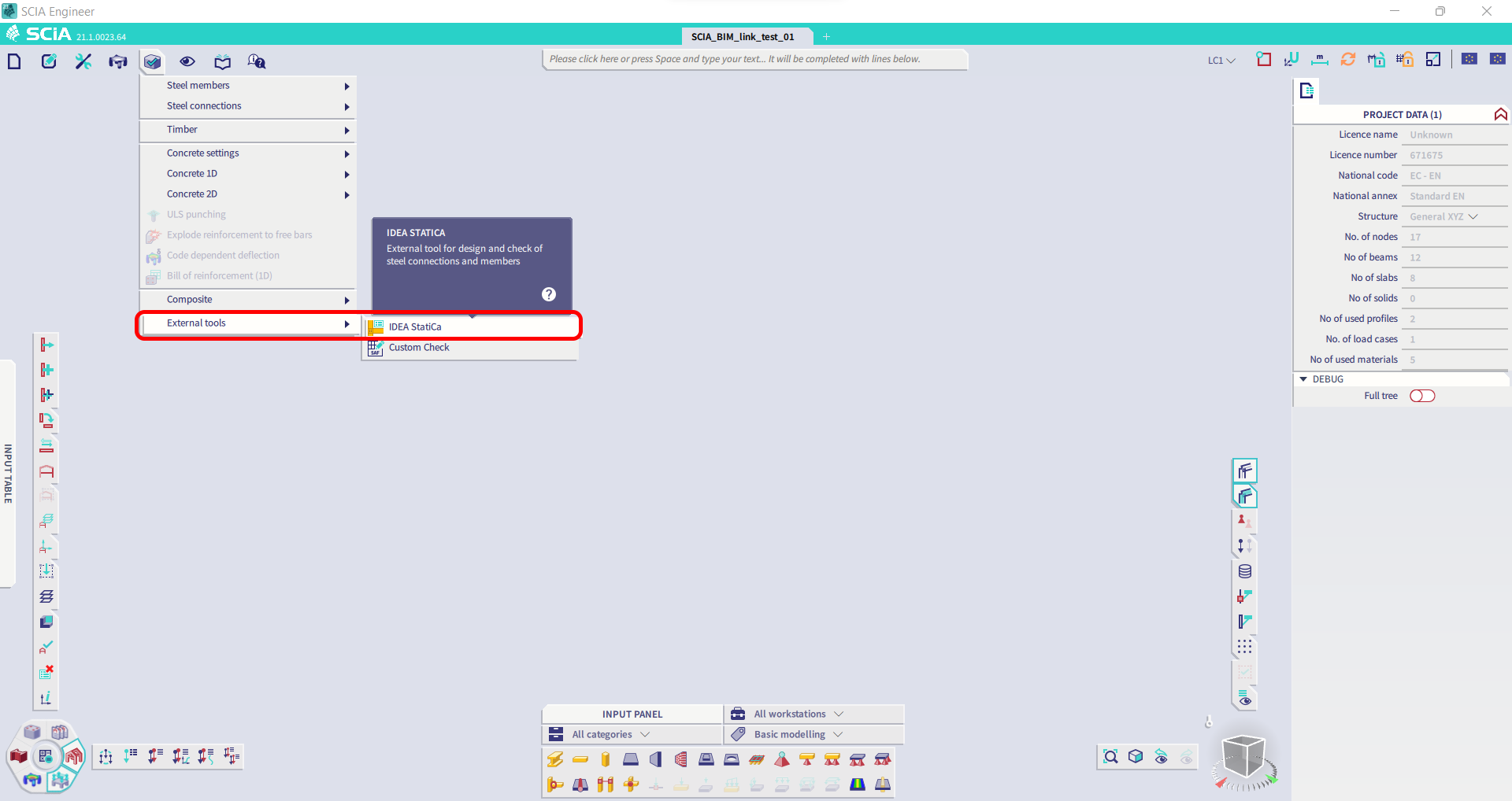
Korlátozás: Ez a funkció nem érhető el a SCIA 21.1 Legacy verziójában.
Megkerülő megoldás: Használja a SCIA 21.1 alapértelmezett felhasználói felületét.
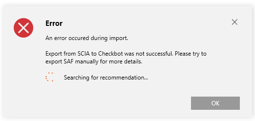
Korlátozás: A SCIA nem tudja létrehozni a Bimlink kommunikációhoz szükséges SAF-fájlt. A probléma a következő hibaüzenettel jelentkezik a Checkbot-ban, illetve a következő üzenettel, amikor a SAF-modellt közvetlenül a SCIA-ból exportálják.

Megkerülő megoldás: A javításhoz módosítsa az átviteli módszer kiválasztását Tributary Area helyett Accurate (FEM) értékre.
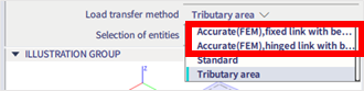
FONTOS MEGJEGYZÉS: A Scia Engineer 26.0 verzióban a SAF-exportálás javításra került, és a fent látható hibaüzenet már nem jelenik meg.
Korlátozás: A szabványos kombinációk nem importálhatók az IDEA StatiCa Checkbot alkalmazásba.
Megkerülő megoldás: A SCIA Engineer-ben az exportálás előtt bontsa fel a kombinációkat burkolókra vagy lineáris kombinációkra.

Korlátozás: A „Standard"-tól eltérő LCS-típusú szerkezeti elemek az exportálás meghiúsulását okozzák a Checkbot-ba való exportáláskor.
Megkerülő megoldás: Ha a Checkbot-ba való importálás során a következő hiba jelenik meg:
Lépjen a SCIA-ba, és végezzen manuális SAF-fájl exportálást.
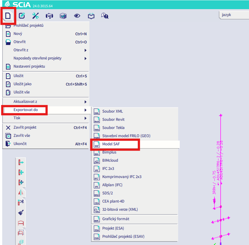
Ha az exportálás sikertelen, kattintson az „INFO" gombra, és a felső sorok tájékoztatnak azokról a szerkezeti elemekről, amelyek nem „standard" LCS-t használnak.
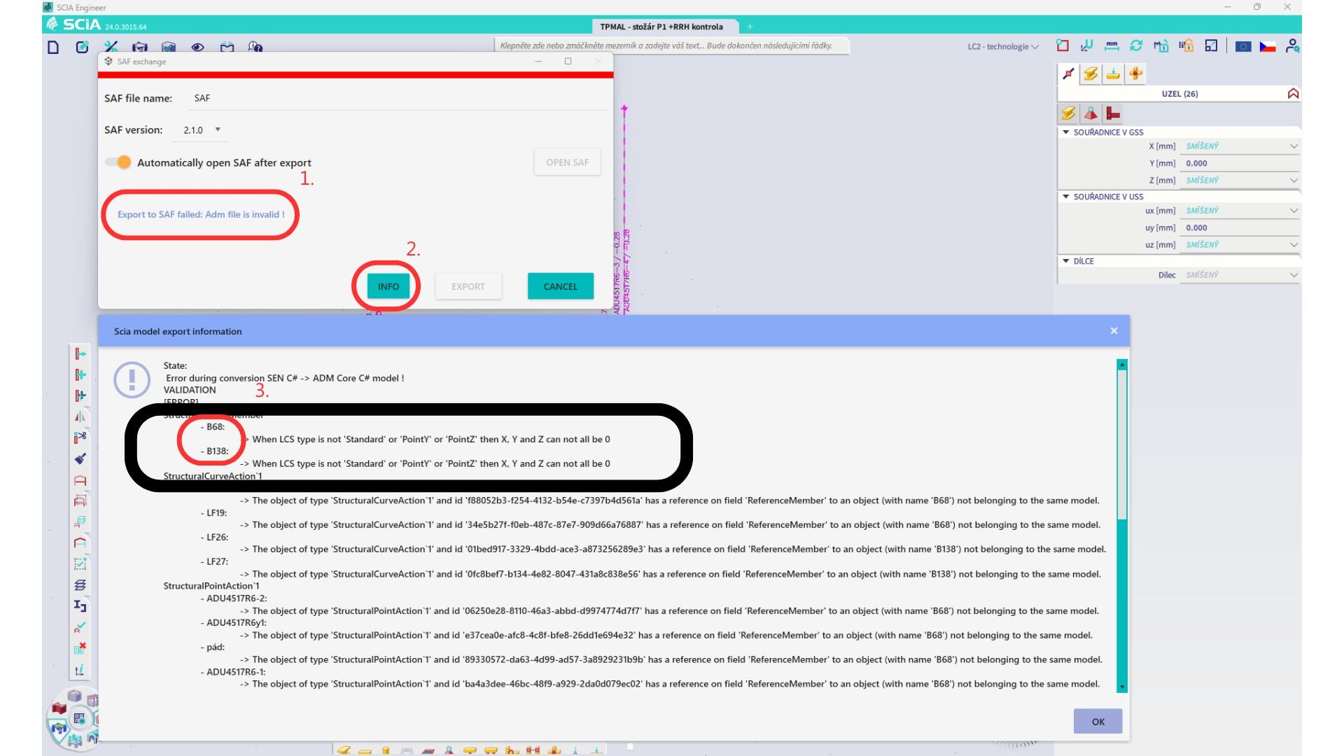
Keresse meg az érintett szerkezeti elemeket, és módosítsa LCS-üket „standard" értékre. Számítsa újra a modellt, majd indítsa el újra a BIM-kapcsolatot.
Korlátozás: A Scia Engineer-ben lévő, meghatározott „Master load case"-t tartalmazó teherkombinációkat tartalmazó burkoló kombinációk az importálás után nem kerülnek helyesen kombinálásra az IDEA StatiCa Checkbot alkalmazásban a SAF-fájlból hiányzó információk miatt.
Megkerülő megoldás: Az exportálás előtt bontsa fel a SCIA Engineer-ben lévő, meghatározott „Master load case"-t tartalmazó burkoló kombinációkat lineáris kombinációkra.

Korlátozás: A tehercsoportban lévő Together reláció nem kerül figyelembevételre az IDEA StatiCa Checkbot alkalmazásba való importálás után, és ez eltérő belső erőket okoz a Scia Engineer és a Checkbot között.

Megkerülő megoldás: Az exportálás előtt bontsa fel a burkoló kombinációkat lineáris kombinációkra a Scia Engineer-ben. A másik lehetőség az IDEA StatiCa Connection közvetlen kapcsolatának használata.