
SCIA Engineer BIM link for connection design (old)
1 How to activate the link
- Download and install (as administrator) the latest version of IDEA StatiCa
- Make sure that you are using the supported version of SCIA Engineer
IDEA StatiCa automatically integrates the BIM link into your CAD/CAE software during its installation. You can check the status and activate more BIM links for later installed software in the BIM link installer.
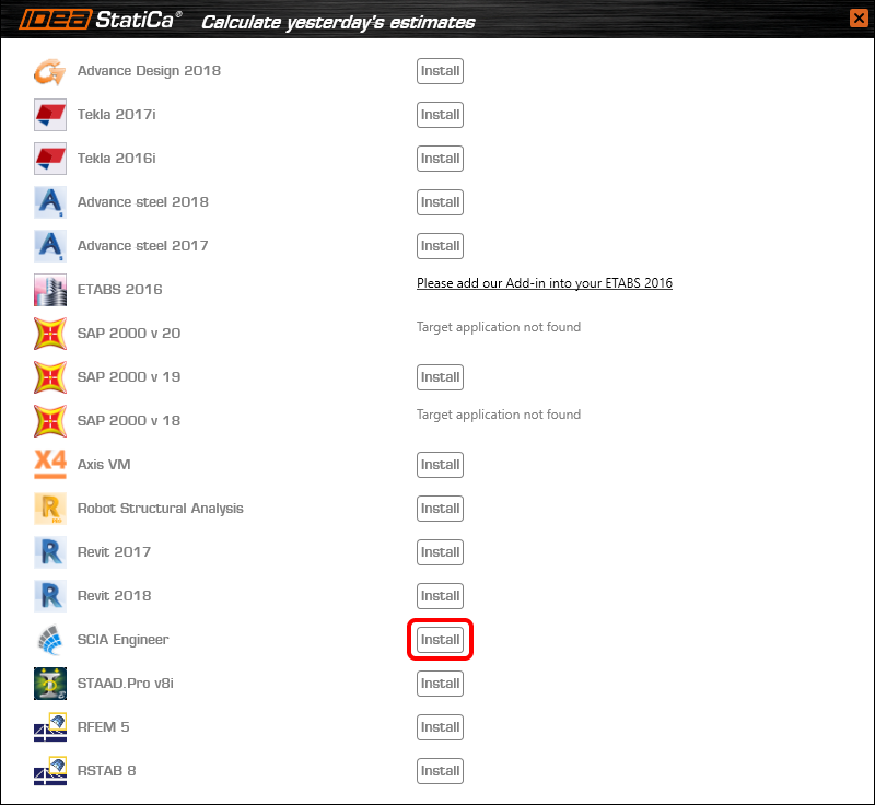
Open IDEA StatiCa and navigate to the panel BIM and open the BIM link installer. A notification "Run as administrator" may appear, please confirm with the Yes button.

Select the software to integrate the IDEA StatiCa BIM link, click the Install button and check the Installed status.
2 How to use the link
Download the attached project, open it in SCIA Engineer, and run the linear analysis to get the internal forces over the structure.
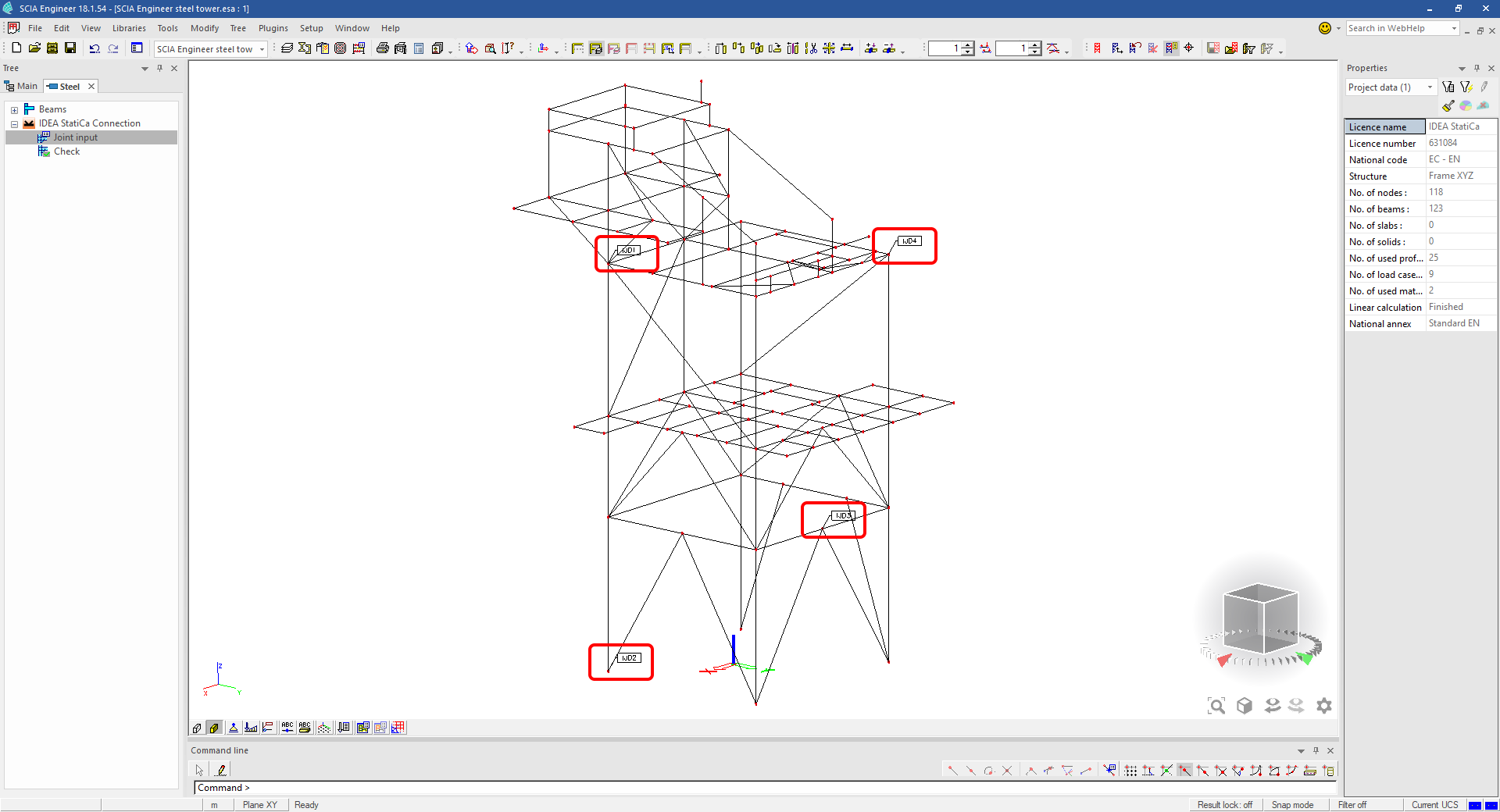
In the Main menu, go to the tab Steel.

Go to the IDEA StatiCa Connection menu. Add a joint to this SCIA Engineer project list of joints by selecting the members of a joint, then by clicking on Joint input and typing the name of it (name of the IDEA StatiCa Connection project file) and OK.

Open the command Check, run the command Export to IDEA Statica Connection in the Actions menu, and select the joint sign in the workspace.

Application IDEA StatiCa Connection opens and you can design connections of the joint.
3 Design
Joint geometry and load effects have been imported, you can start designing.

You will define a set of manufacturing operations to model connections between members. Hide the Load effects tree and right-click on Operations to add a new operation Cut.


In the next step add another manufacturing operation Endplate and modify its parameters.


Then add a Connecting plate operation and set its parameters for the appropriate member.


Right-click on the tongue plate, open the plate Editor and reshape the Tongue by adding an operation Rounding.


Next, you will again right-click on the gusset plate and in the Editor reshape the Gusset plate by adding a Bevel operation.


Now you can add a Stiffener operation and modify its properties.


Add another Cut operation for the upper member.


Again, use the Cut operation for the diagonals.


Copy the last cut operation and set it for the other diagonal.


In the next step add a Stiffener to the main column.


Finish the design by adding a Fin plate operation to connect the last member.


4 Check
You can start the analysis by clicking Calculate in the ribbon. The analysis model is automatically generated, the calculation is performed for all the load cases and you can see the Overall check displayed together with basic values of check results.

Go to the display tab Check and there activate Equivalent stress, Bolt forces, Mesh and Deformed and change the deformation scale in the ribbon to get a full picture of what is happening in the joint.

By default, you can see the For extreme results envelope of all the load effects, so the most unfavorable results are displayed all together. If you click on any item (e.g. the fin plate), it shows you which load effect is the most unfavorable for it in the ribbon.

You can also display and browse results for each load effect separately by changing the For the extreme option to For current in the ribbon.

5 Report
At last, go to the tab Report. IDEA StatiCa offers a fully customizable report to print out or save in an editable format.


You have imported a joint from SCIA Engineer and designed and code-checked it according to Eurocode.
6 How to update the project
Save the project and close the application Connection. All joints exported from an SCIA Engineer project to IDEA StatiCa are kept on the list as a part of the SCIA Engineer project file for later updates.
Note: In case you need to send a simple IDEA StatiCa file, you can "save as" a copy of the opened joint model to the desired folder
Go back to the SCIA Engineer model, change the cross-section of one of the diagonals, and start the Calculation of linear analysis again.

Open again the command Check, run the command Export to IDEA StatiCa Connection in the Actions menu, and select the joint sign in the workspace.

IDEA StatiCa opens and you can see the updated geometry while the design and settings adjust to the new state.

You can adjust the design, recalculate the joint code-check and save the project in IDEA StatiCa again and continue with exporting other joints.
SCIA Engineer의 알려진 제한 사항
제한 사항: 비선형 조합은 IDEA StatiCa Checkbot 애플리케이션으로 가져올 수 없습니다.
제한 사항: "α"를 사용한 부재 회전은 SCIA Engineer에서 Checkbot으로 가져올 수 없습니다.
해결 방법: 대신 "LCS Rotation"을 사용하여 부재를 회전하면 부재 회전이 올바르게 가져와집니다.

제한 사항: SCIA Engineer에서 모델링된 헌치는 Checkbot으로 가져오지 않습니다.
해결 방법: 헌치는 IDEA StatiCa Connection에서 작업(Operations)을 사용하여 별도로 모델링해야 합니다.

제한 사항: "member system-line at"을 사용하여 모델링된 편심은 버전 25.0 이하에서는 가져오지 않습니다. 버전 25.1.0부터 이 제한 사항이 제거되었으며 부재는 정의된 시스템 선과 함께 가져와집니다.
해결 방법: 편심은 ez 또는 ey 값을 통해 정의해야 합니다. 부재 시스템 선은 "Centre"로 설정해야 합니다.

SCIA Engineer 버전 21.1에서 IDEA StatiCa는 SCIA Engineer와 Checkbot 애플리케이션 간의 BIM 링크를 사용하는 또 다른 옵션을 도입했습니다.
제한 사항: 이 기능은 SCIA 21.1의 Legacy 버전에는 포함되어 있지 않습니다.
해결 방법: SCIA 21.1의 기본 UX를 사용하십시오.
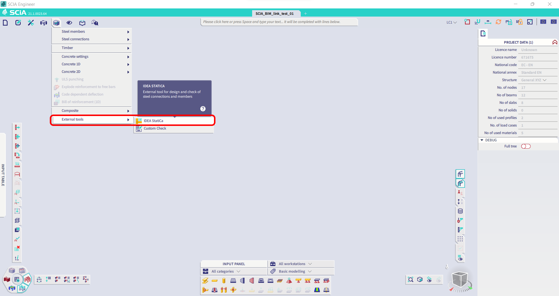
제한 사항: SCIA가 Bimlink 통신에 사용되는 SAF 파일을 생성할 수 없습니다. 이 문제는 Checkbot에서 다음 오류로 나타나며, SCIA에서 SAF 모델을 직접 내보낼 때 다음 메시지가 표시됩니다.

해결 방법: 이를 해결하려면 전달 방법 선택을 Tributary Area에서 Accurate (FEM)으로 변경하십시오.
중요 참고 사항: 버전 Scia Engineer 26.0에서 SAF 내보내기 문제가 수정되었으며, 위에 표시된 오류 메시지는 더 이상 나타나지 않습니다.
제한 사항: 표준 조합은 IDEA StatiCa Checkbot 애플리케이션으로 가져올 수 없습니다.
해결 방법: SCIA Engineer에서 내보내기 전에 조합을 포락선 또는 선형 조합으로 분해하십시오.

제한 사항: "Standard" 이외의 LCS 유형을 가진 부재는 Checkbot으로의 내보내기를 실패하게 합니다.
해결 방법: Checkbot으로 가져오는 중 다음 오류가 나타날 때.
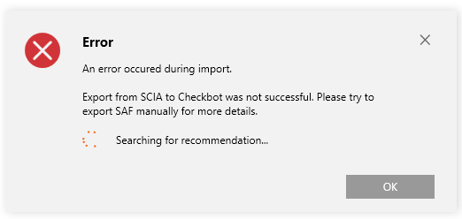
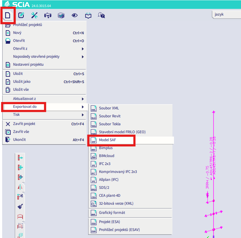
SCIA로 이동하여 SAF 파일을 수동으로 내보내십시오.
내보내기가 실패하면 "INFO"를 클릭하면 상단 줄에 "standard" 이외의 LCS를 사용하는 부재에 대한 정보가 표시됩니다.
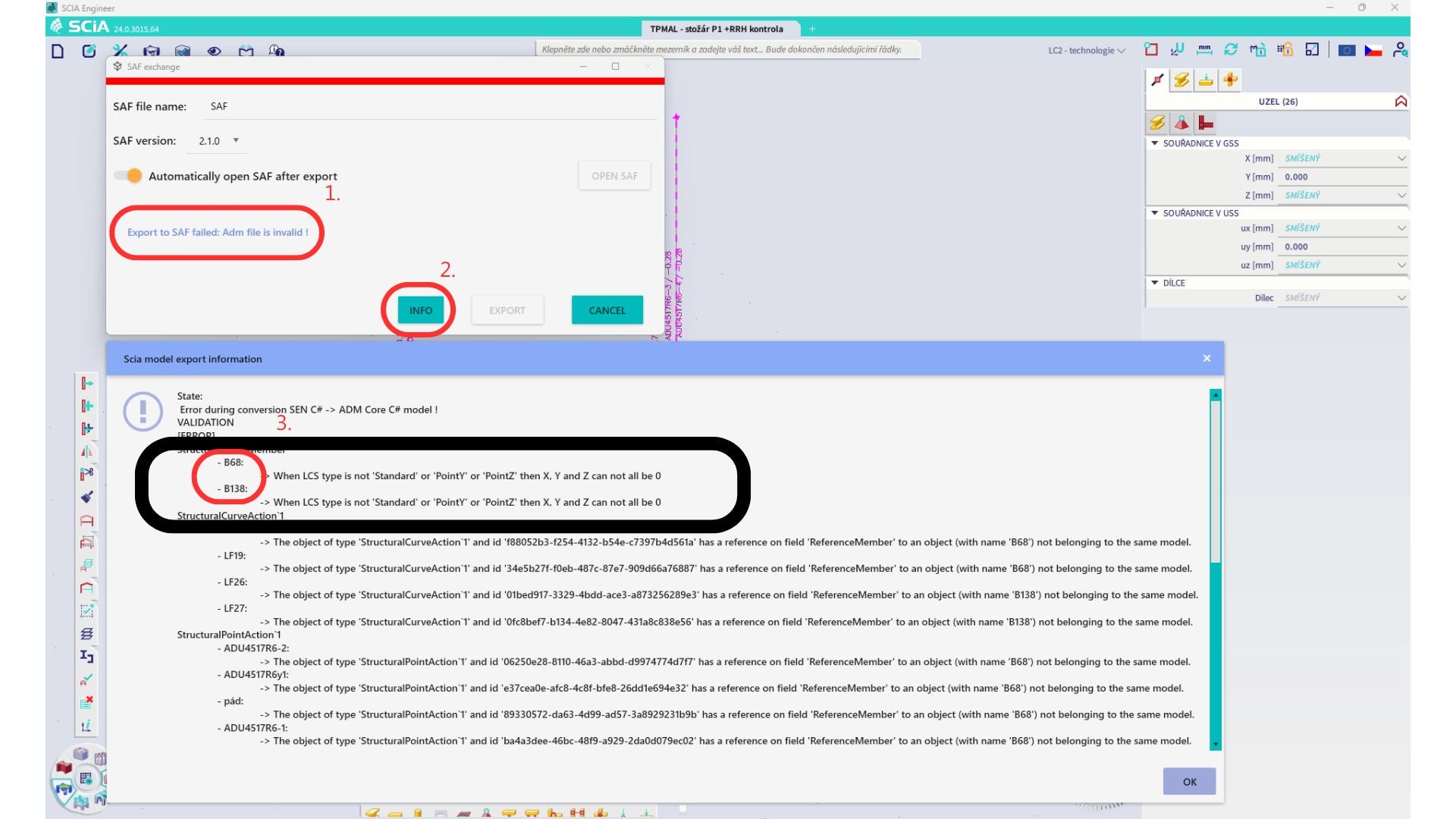
해당 부재를 찾아 LCS를 "standard"로 변경하십시오. 재계산 후 BIM 링크를 다시 실행하십시오.
제한 사항: SAF 파일의 정보 누락으로 인해 "Master load case"가 정의된 하중 케이스를 포함하는 Scia Engineer의 포락선 조합은 IDEA StatiCa Checkbot 애플리케이션으로 가져온 후 올바르게 조합되지 않습니다.
해결 방법: 내보내기 전에 SCIA Engineer에서 "Master load case"가 정의된 하중 케이스를 포함하는 포락선 조합을 선형 조합으로 분해하십시오.

제한 사항: 하중 그룹의 Together 관계는 IDEA StatiCa Checkbot 애플리케이션으로 가져온 후 고려되지 않으며, 이로 인해 Scia Engineer와 Checkbot 간의 내력이 일치하지 않습니다.

해결 방법: 내보내기 전에 Scia Engineer에서 포락선 조합을 선형 조합으로 분해하십시오. 두 번째 방법은 IDEA StatiCa Connection에 직접 링크를 사용하는 것입니다.