
SCIA Engineer BIM link for connection design (old)
1 How to activate the link
- Download and install (as administrator) the latest version of IDEA StatiCa
- Make sure that you are using the supported version of SCIA Engineer
IDEA StatiCa automatically integrates the BIM link into your CAD/CAE software during its installation. You can check the status and activate more BIM links for later installed software in the BIM link installer.
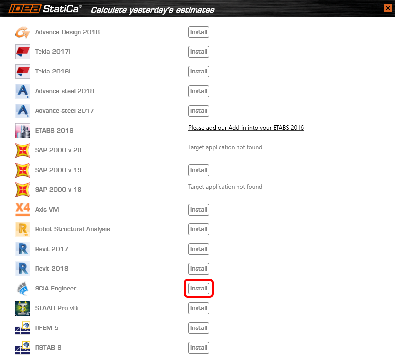
Open IDEA StatiCa and navigate to the panel BIM and open the BIM link installer. A notification "Run as administrator" may appear, please confirm with the Yes button.

Select the software to integrate the IDEA StatiCa BIM link, click the Install button and check the Installed status.
2 How to use the link
Download the attached project, open it in SCIA Engineer, and run the linear analysis to get the internal forces over the structure.
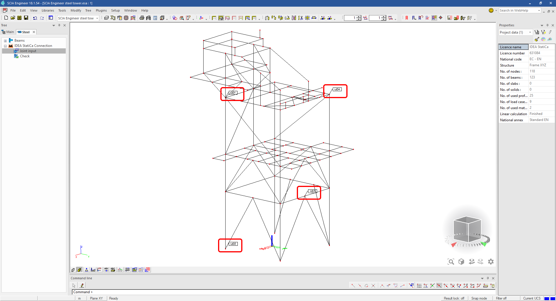
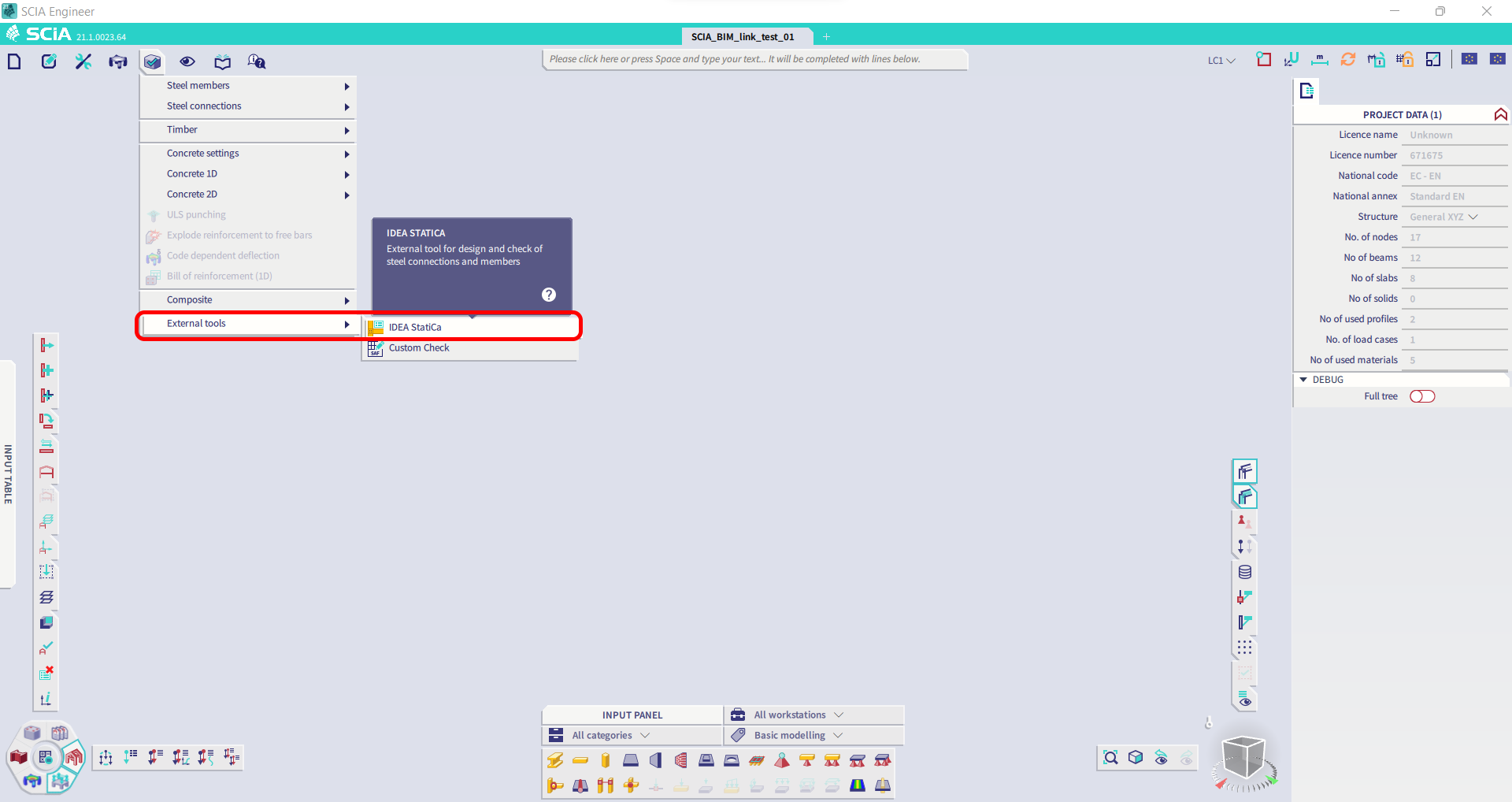
In the Main menu, go to the tab Steel.

Go to the IDEA StatiCa Connection menu. Add a joint to this SCIA Engineer project list of joints by selecting the members of a joint, then by clicking on Joint input and typing the name of it (name of the IDEA StatiCa Connection project file) and OK.

Open the command Check, run the command Export to IDEA Statica Connection in the Actions menu, and select the joint sign in the workspace.

Application IDEA StatiCa Connection opens and you can design connections of the joint.
3 Design
Joint geometry and load effects have been imported, you can start designing.

You will define a set of manufacturing operations to model connections between members. Hide the Load effects tree and right-click on Operations to add a new operation Cut.


In the next step add another manufacturing operation Endplate and modify its parameters.


Then add a Connecting plate operation and set its parameters for the appropriate member.


Right-click on the tongue plate, open the plate Editor and reshape the Tongue by adding an operation Rounding.


Next, you will again right-click on the gusset plate and in the Editor reshape the Gusset plate by adding a Bevel operation.


Now you can add a Stiffener operation and modify its properties.


Add another Cut operation for the upper member.


Again, use the Cut operation for the diagonals.


Copy the last cut operation and set it for the other diagonal.


In the next step add a Stiffener to the main column.


Finish the design by adding a Fin plate operation to connect the last member.


4 Check
You can start the analysis by clicking Calculate in the ribbon. The analysis model is automatically generated, the calculation is performed for all the load cases and you can see the Overall check displayed together with basic values of check results.

Go to the display tab Check and there activate Equivalent stress, Bolt forces, Mesh and Deformed and change the deformation scale in the ribbon to get a full picture of what is happening in the joint.

By default, you can see the For extreme results envelope of all the load effects, so the most unfavorable results are displayed all together. If you click on any item (e.g. the fin plate), it shows you which load effect is the most unfavorable for it in the ribbon.

You can also display and browse results for each load effect separately by changing the For the extreme option to For current in the ribbon.

5 Report
At last, go to the tab Report. IDEA StatiCa offers a fully customizable report to print out or save in an editable format.


You have imported a joint from SCIA Engineer and designed and code-checked it according to Eurocode.
6 How to update the project
Save the project and close the application Connection. All joints exported from an SCIA Engineer project to IDEA StatiCa are kept on the list as a part of the SCIA Engineer project file for later updates.
Note: In case you need to send a simple IDEA StatiCa file, you can "save as" a copy of the opened joint model to the desired folder
Go back to the SCIA Engineer model, change the cross-section of one of the diagonals, and start the Calculation of linear analysis again.

Open again the command Check, run the command Export to IDEA StatiCa Connection in the Actions menu, and select the joint sign in the workspace.

IDEA StatiCa opens and you can see the updated geometry while the design and settings adjust to the new state.

You can adjust the design, recalculate the joint code-check and save the project in IDEA StatiCa again and continue with exporting other joints.
Limitări cunoscute pentru SCIA Engineer
Limitare: Combinațiile neliniare nu pot fi importate în aplicația IDEA StatiCa Checkbot.
Limitare: Rotația elementelor folosind „α" nu poate fi importată din SCIA Engineer în Checkbot
Soluție alternativă: Rotiți elementul folosind „LCS Rotation" în schimb; rotația elementelor va fi importată corect.

Limitare: Vutele modelate în SCIA Engineer nu sunt importate în Checkbot.
Soluție alternativă: Vutele trebuie modelate separat în IDEA StatiCa Connection folosind Operații.

Limitare: Excentricitatea modelată folosind „member system-line at" nu este importată în versiunea 25.0 și versiunile anterioare. Începând cu versiunea 25.1.0, această limitare a fost eliminată și elementele sunt importate cu linia de sistem definită.
Soluție alternativă: Excentricitatea trebuie definită printr-o valoare ez sau ey. Linia de sistem a elementului trebuie setată la „Centre".

Odată cu versiunea SCIA Engineer 21.1, IDEA StatiCa a introdus o altă opțiune de utilizare a legăturii BIM între SCIA Engineer și aplicația Checkbot.
Limitare: Această funcționalitate nu este inclusă în versiunea Legacy a SCIA 21.1.
Soluție alternativă: Utilizați interfața implicită a SCIA 21.1.
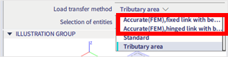
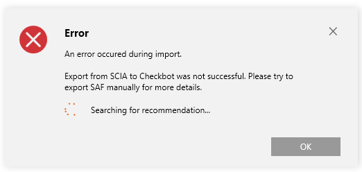
Limitare: SCIA nu poate crea un fișier SAF utilizat pentru comunicarea prin Bimlink. Problema se manifestă prin următoarea eroare în Checkbot și prin următorul mesaj la exportul direct al modelului SAF din SCIA.

Soluție alternativă: Pentru a remedia problema, schimbați selecția metodei de transfer din Tributary Area în Accurate (FEM).
NOTĂ IMPORTANTĂ: În versiunea Scia Engineer 26.0, exportul în SAF a fost remediat, iar mesajul de eroare afișat mai sus nu mai apare.
Limitare: Combinațiile standard nu pot fi importate în aplicația IDEA StatiCa Checkbot.
Soluție alternativă: În SCIA Engineer, descompuneți combinațiile în anvelopă sau combinații liniare înainte de export.

Limitare: Elementele cu un tip LCS diferit de „Standard" determină eșuarea exportului în Checkbot.
Soluție alternativă: Când apare următoarea eroare în timpul importului în Checkbot.
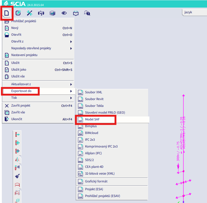
Navigați în SCIA și efectuați un export manual al fișierului SAF.
Dacă exportul eșuează, faceți clic pe „INFO" și primele linii vă informează despre elementele care utilizează un LCS diferit de „standard".
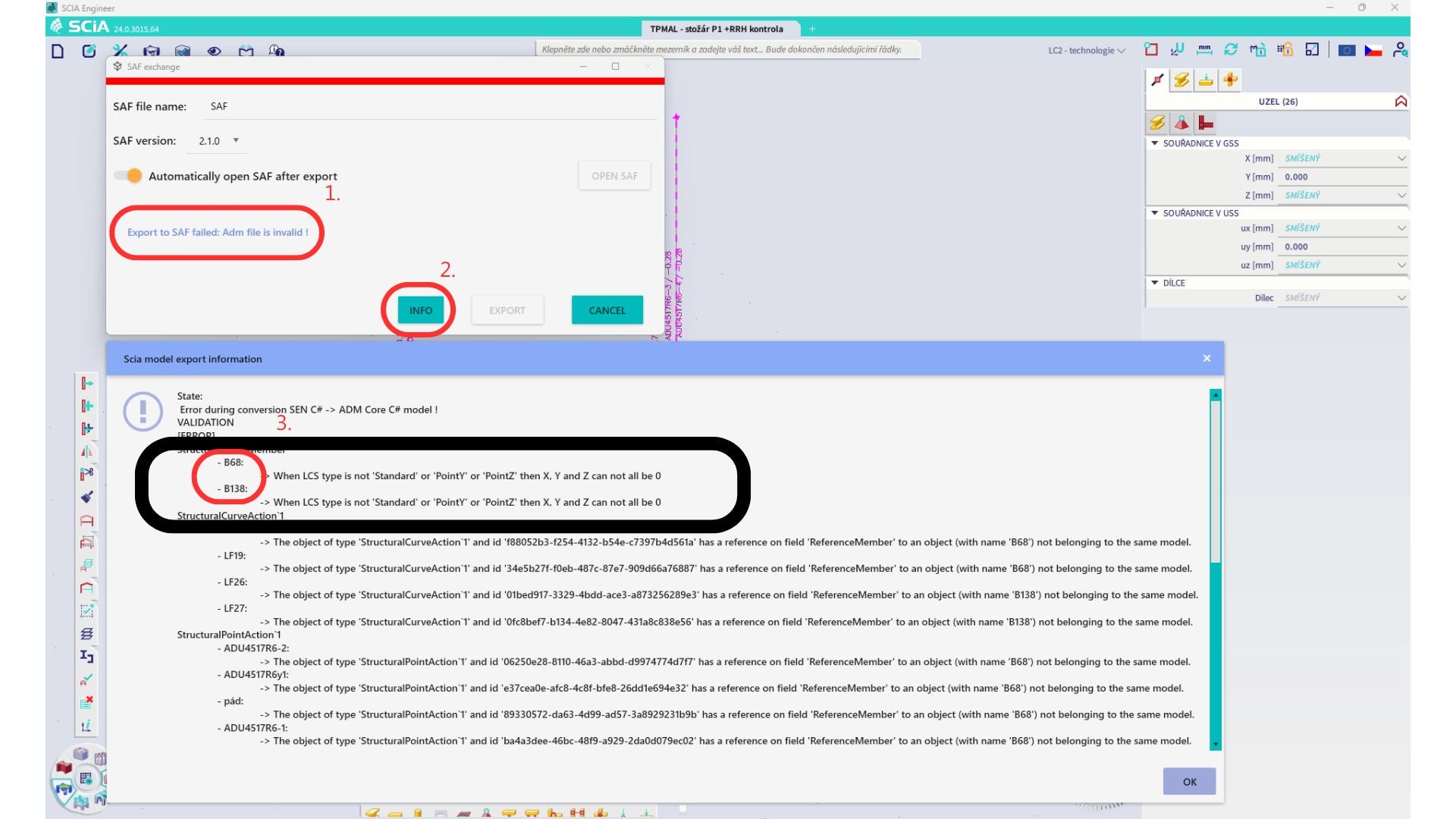
Localizați elementele și schimbați LCS-ul acestora la „standard". Recalculați și relansați legătura BIM.
Limitare: Combinațiile de anvelopă din Scia Engineer care conțin cazuri de încărcare cu un „Master load case" definit nu sunt combinate corect după import în aplicația IDEA StatiCa Checkbot, din cauza informațiilor lipsă din fișierul SAF.
Soluție alternativă: Înainte de export, descompuneți combinațiile de anvelopă din SCIA Engineer care conțin cazuri de încărcare cu un „Master load case" definit în combinații liniare.

Limitare: Relația Together din grupul de încărcări nu este luată în considerare după import în aplicația IDEA StatiCa Checkbot și a cauzat forțe interioare inconsistente între Scia Engineer și Checkbot.

Soluție alternativă: Înainte de export, descompuneți combinațiile de anvelopă în combinații liniare în Scia Engineer. A doua modalitate este utilizarea legăturii directe cu IDEA StatiCa Connection.