
SCIA Engineer BIM link for connection design (old)
1 How to activate the link
- Download and install (as administrator) the latest version of IDEA StatiCa
- Make sure that you are using the supported version of SCIA Engineer
IDEA StatiCa automatically integrates the BIM link into your CAD/CAE software during its installation. You can check the status and activate more BIM links for later installed software in the BIM link installer.
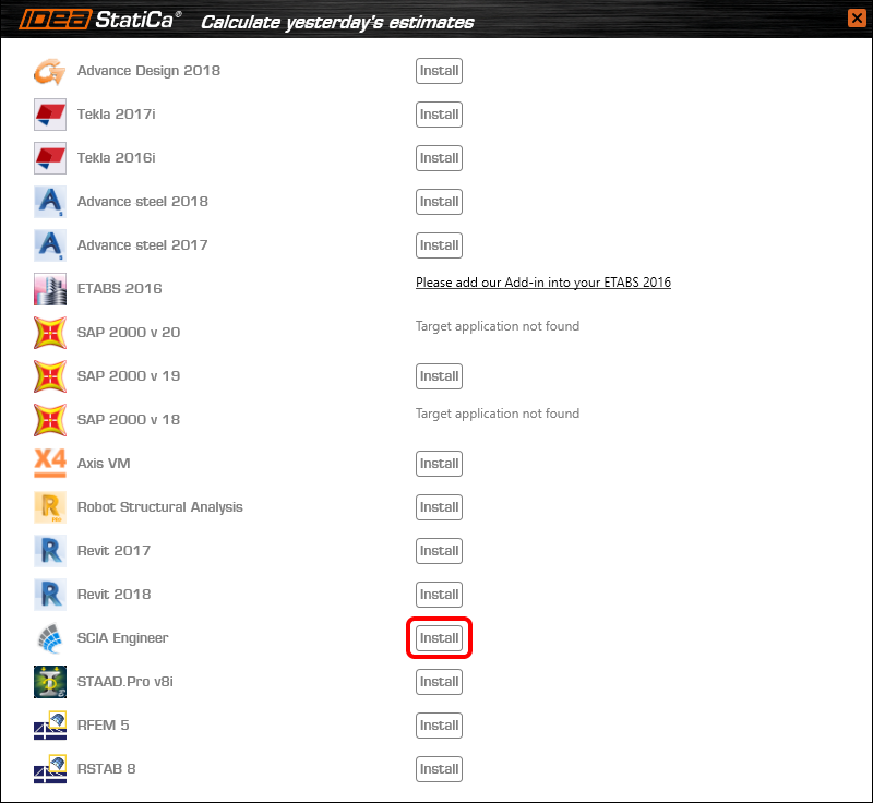
Open IDEA StatiCa and navigate to the panel BIM and open the BIM link installer. A notification "Run as administrator" may appear, please confirm with the Yes button.

Select the software to integrate the IDEA StatiCa BIM link, click the Install button and check the Installed status.
2 How to use the link
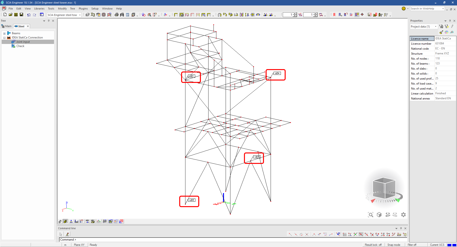
Download the attached project, open it in SCIA Engineer, and run the linear analysis to get the internal forces over the structure.
In the Main menu, go to the tab Steel.

Go to the IDEA StatiCa Connection menu. Add a joint to this SCIA Engineer project list of joints by selecting the members of a joint, then by clicking on Joint input and typing the name of it (name of the IDEA StatiCa Connection project file) and OK.

Open the command Check, run the command Export to IDEA Statica Connection in the Actions menu, and select the joint sign in the workspace.

Application IDEA StatiCa Connection opens and you can design connections of the joint.
3 Design
Joint geometry and load effects have been imported, you can start designing.

You will define a set of manufacturing operations to model connections between members. Hide the Load effects tree and right-click on Operations to add a new operation Cut.


In the next step add another manufacturing operation Endplate and modify its parameters.


Then add a Connecting plate operation and set its parameters for the appropriate member.


Right-click on the tongue plate, open the plate Editor and reshape the Tongue by adding an operation Rounding.


Next, you will again right-click on the gusset plate and in the Editor reshape the Gusset plate by adding a Bevel operation.


Now you can add a Stiffener operation and modify its properties.


Add another Cut operation for the upper member.


Again, use the Cut operation for the diagonals.


Copy the last cut operation and set it for the other diagonal.


In the next step add a Stiffener to the main column.


Finish the design by adding a Fin plate operation to connect the last member.


4 Check
You can start the analysis by clicking Calculate in the ribbon. The analysis model is automatically generated, the calculation is performed for all the load cases and you can see the Overall check displayed together with basic values of check results.

Go to the display tab Check and there activate Equivalent stress, Bolt forces, Mesh and Deformed and change the deformation scale in the ribbon to get a full picture of what is happening in the joint.

By default, you can see the For extreme results envelope of all the load effects, so the most unfavorable results are displayed all together. If you click on any item (e.g. the fin plate), it shows you which load effect is the most unfavorable for it in the ribbon.

You can also display and browse results for each load effect separately by changing the For the extreme option to For current in the ribbon.

5 Report
At last, go to the tab Report. IDEA StatiCa offers a fully customizable report to print out or save in an editable format.


You have imported a joint from SCIA Engineer and designed and code-checked it according to Eurocode.
6 How to update the project
Save the project and close the application Connection. All joints exported from an SCIA Engineer project to IDEA StatiCa are kept on the list as a part of the SCIA Engineer project file for later updates.
Note: In case you need to send a simple IDEA StatiCa file, you can "save as" a copy of the opened joint model to the desired folder
Go back to the SCIA Engineer model, change the cross-section of one of the diagonals, and start the Calculation of linear analysis again.

Open again the command Check, run the command Export to IDEA StatiCa Connection in the Actions menu, and select the joint sign in the workspace.

IDEA StatiCa opens and you can see the updated geometry while the design and settings adjust to the new state.

You can adjust the design, recalculate the joint code-check and save the project in IDEA StatiCa again and continue with exporting other joints.
Limitazioni note per SCIA Engineer
Limitazione: Le combinazioni non lineari non possono essere importate nell'applicazione IDEA StatiCa Checkbot.
Limitazione: La rotazione degli elementi tramite "α" non può essere importata da SCIA Engineer a Checkbot
Soluzione alternativa: Ruotare l'elemento utilizzando "LCS Rotation", la rotazione degli elementi verrà importata correttamente.

Limitazione: Le mensole rastremate modellate in SCIA Engineer non vengono importate in Checkbot.
Soluzione alternativa: Le mensole rastremate devono essere modellate separatamente in IDEA StatiCa Connection utilizzando le Operazioni.

Limitazione: L'eccentricità modellata tramite "member system-line at" non viene importata nella versione 25.0 e precedenti. Dalla versione 25.1.0, questa limitazione è stata rimossa e gli elementi vengono importati con la linea d'asse definita.
Soluzione alternativa: L'eccentricità deve essere definita tramite un valore ez o ey. La linea d'asse dell'elemento deve essere impostata su "Centre".

Con SCIA Engineer versione 21.1, IDEA StatiCa ha introdotto un'ulteriore opzione per utilizzare il collegamento BIM tra SCIA Engineer e l'applicazione Checkbot.
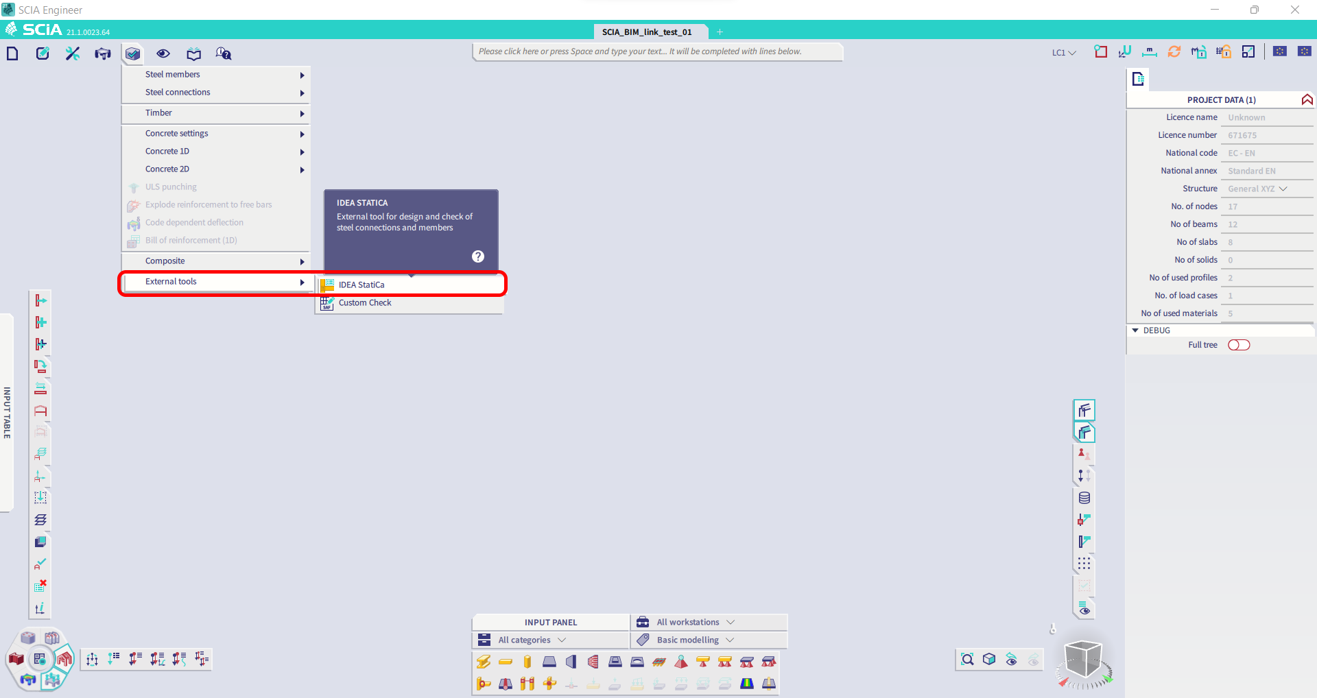
Limitazione: Questa funzionalità non è integrata nella versione Legacy di SCIA 21.1.
Soluzione alternativa: Utilizzare l'interfaccia utente predefinita di SCIA 21.1.
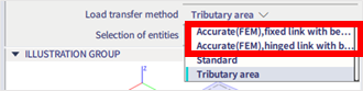
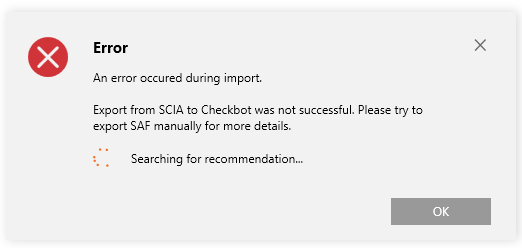
Limitazione: SCIA non è in grado di creare un file SAF utilizzato per la comunicazione Bimlink. Il problema si manifesta con il seguente errore in Checkbot e il seguente messaggio durante l'esportazione del modello SAF direttamente da SCIA.

Soluzione alternativa: Per risolvere il problema, modificare la selezione del metodo di trasferimento da Tributary Area a Accurate (FEM).
NOTA IMPORTANTE: Nella versione Scia Engineer 26.0, l'esportazione in SAF è stata corretta e il messaggio di errore visualizzato sopra non compare più.
Limitazione: Le combinazioni standard non possono essere importate nell'applicazione IDEA StatiCa Checkbot.
Soluzione alternativa: In SCIA Engineer, scomporre le combinazioni in inviluppi o combinazioni lineari prima dell'esportazione.

Limitazione: Gli elementi con un tipo LCS diverso da "Standard" causano il fallimento dell'esportazione in Checkbot.
Soluzione alternativa: Quando durante un'importazione in Checkbot compare il seguente errore.
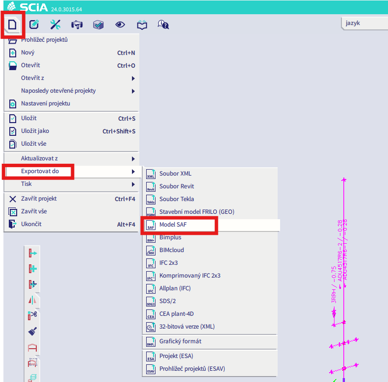
Accedere a SCIA ed eseguire un'esportazione manuale del file SAF.
Se l'esportazione fallisce, fare clic su "INFO" e le righe in cima informano sugli elementi che utilizzano un LCS diverso da "standard".
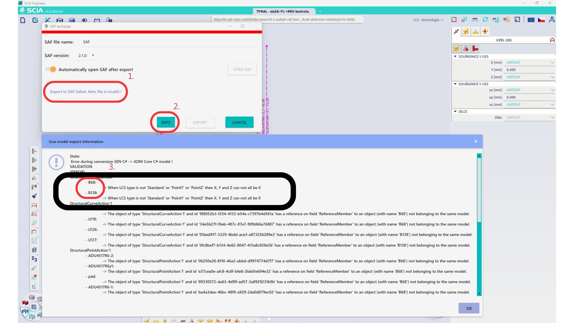
Individuare gli elementi e modificare il loro LCS in "standard". Ricalcolare e avviare nuovamente il collegamento BIM.
Limitazione: Le combinazioni a inviluppo in Scia Engineer contenenti casi di carico con un "Master load case" definito non vengono combinate correttamente dopo l'importazione nell'applicazione IDEA StatiCa Checkbot a causa di informazioni mancanti nel file SAF.
Soluzione alternativa: Prima dell'esportazione, scomporre le combinazioni a inviluppo contenute in SCIA Engineer e contenenti casi di carico con un "Master load case" definito in combinazioni lineari.

Limitazione: La relazione Together nel gruppo di carico non viene presa in considerazione dopo l'importazione nell'applicazione IDEA StatiCa Checkbot e causa forze interne incoerenti tra Scia Engineer e Checkbot.

Soluzione alternativa: Prima dell'esportazione, scomporre le combinazioni a inviluppo in combinazioni lineari in Scia Engineer. Il secondo metodo consiste nell'utilizzare il collegamento diretto a IDEA StatiCa Connection.