
SCIA Engineer BIM link for connection design (old)
1 How to activate the link
- Download and install (as administrator) the latest version of IDEA StatiCa
- Make sure that you are using the supported version of SCIA Engineer
IDEA StatiCa automatically integrates the BIM link into your CAD/CAE software during its installation. You can check the status and activate more BIM links for later installed software in the BIM link installer.
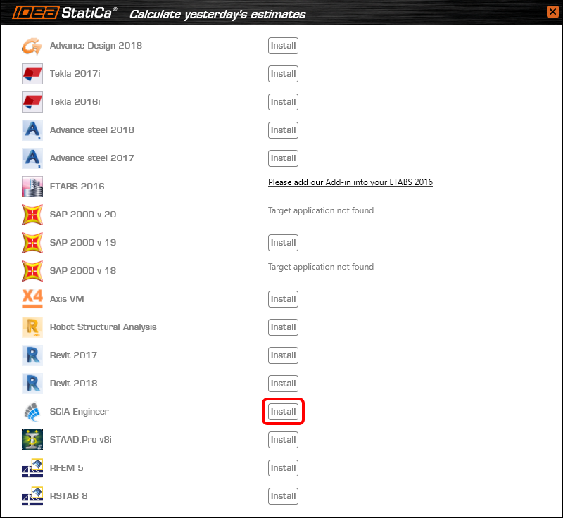
Open IDEA StatiCa and navigate to the panel BIM and open the BIM link installer. A notification "Run as administrator" may appear, please confirm with the Yes button.

Select the software to integrate the IDEA StatiCa BIM link, click the Install button and check the Installed status.
2 How to use the link
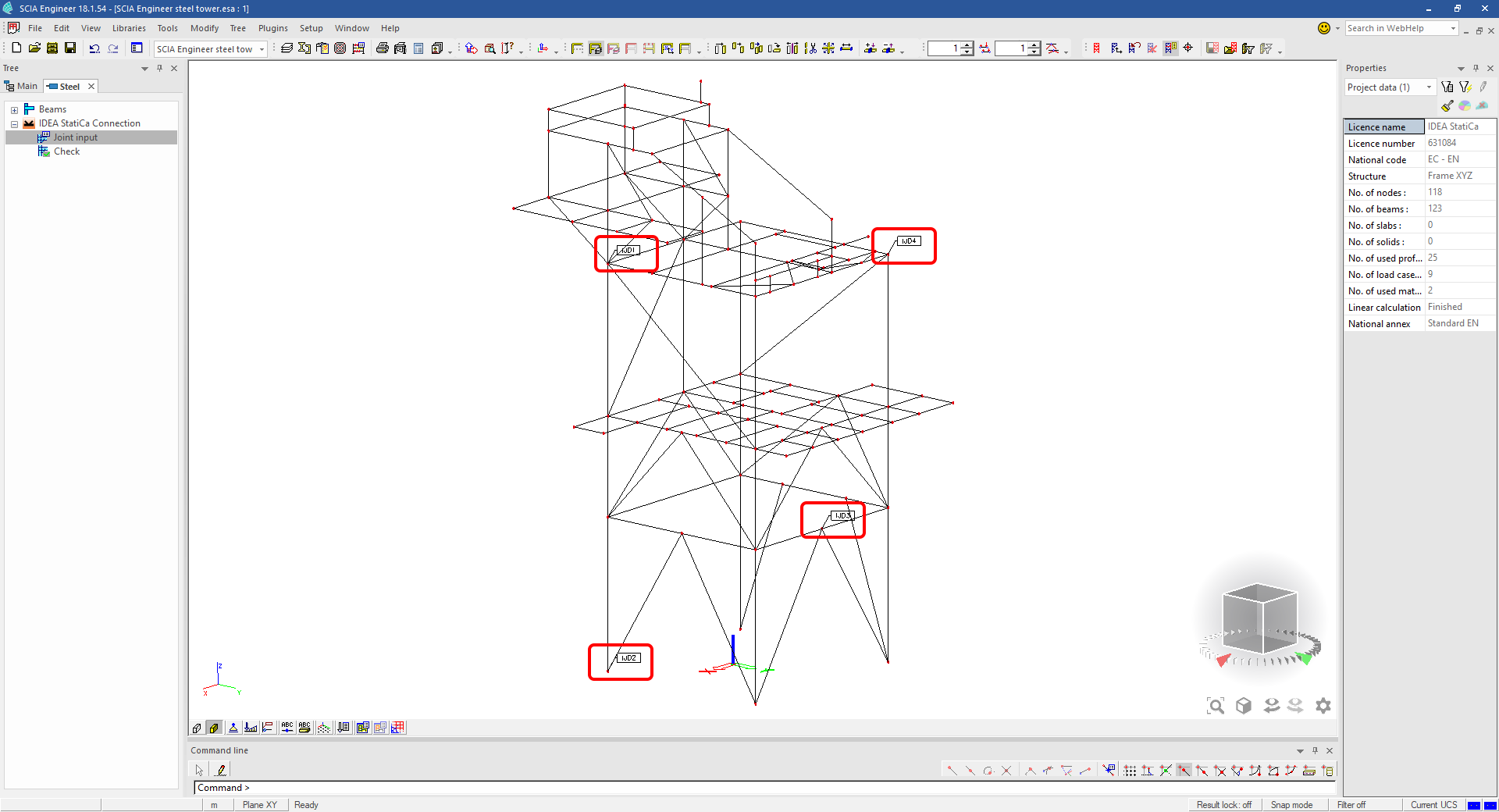
Download the attached project, open it in SCIA Engineer, and run the linear analysis to get the internal forces over the structure.
In the Main menu, go to the tab Steel.

Go to the IDEA StatiCa Connection menu. Add a joint to this SCIA Engineer project list of joints by selecting the members of a joint, then by clicking on Joint input and typing the name of it (name of the IDEA StatiCa Connection project file) and OK.

Open the command Check, run the command Export to IDEA Statica Connection in the Actions menu, and select the joint sign in the workspace.

Application IDEA StatiCa Connection opens and you can design connections of the joint.
3 Design
Joint geometry and load effects have been imported, you can start designing.

You will define a set of manufacturing operations to model connections between members. Hide the Load effects tree and right-click on Operations to add a new operation Cut.


In the next step add another manufacturing operation Endplate and modify its parameters.


Then add a Connecting plate operation and set its parameters for the appropriate member.


Right-click on the tongue plate, open the plate Editor and reshape the Tongue by adding an operation Rounding.


Next, you will again right-click on the gusset plate and in the Editor reshape the Gusset plate by adding a Bevel operation.


Now you can add a Stiffener operation and modify its properties.


Add another Cut operation for the upper member.


Again, use the Cut operation for the diagonals.


Copy the last cut operation and set it for the other diagonal.


In the next step add a Stiffener to the main column.


Finish the design by adding a Fin plate operation to connect the last member.


4 Check
You can start the analysis by clicking Calculate in the ribbon. The analysis model is automatically generated, the calculation is performed for all the load cases and you can see the Overall check displayed together with basic values of check results.

Go to the display tab Check and there activate Equivalent stress, Bolt forces, Mesh and Deformed and change the deformation scale in the ribbon to get a full picture of what is happening in the joint.

By default, you can see the For extreme results envelope of all the load effects, so the most unfavorable results are displayed all together. If you click on any item (e.g. the fin plate), it shows you which load effect is the most unfavorable for it in the ribbon.

You can also display and browse results for each load effect separately by changing the For the extreme option to For current in the ribbon.

5 Report
At last, go to the tab Report. IDEA StatiCa offers a fully customizable report to print out or save in an editable format.


You have imported a joint from SCIA Engineer and designed and code-checked it according to Eurocode.
6 How to update the project
Save the project and close the application Connection. All joints exported from an SCIA Engineer project to IDEA StatiCa are kept on the list as a part of the SCIA Engineer project file for later updates.
Note: In case you need to send a simple IDEA StatiCa file, you can "save as" a copy of the opened joint model to the desired folder
Go back to the SCIA Engineer model, change the cross-section of one of the diagonals, and start the Calculation of linear analysis again.

Open again the command Check, run the command Export to IDEA StatiCa Connection in the Actions menu, and select the joint sign in the workspace.

IDEA StatiCa opens and you can see the updated geometry while the design and settings adjust to the new state.

You can adjust the design, recalculate the joint code-check and save the project in IDEA StatiCa again and continue with exporting other joints.
Znane ograniczenia dla SCIA Engineer
Ograniczenie: Kombinacje nieliniowe nie mogą być importowane do aplikacji IDEA StatiCa Checkbot.
Ograniczenie: Obrót elementów przy użyciu „α" nie może być importowany z SCIA Engineer do Checkbot
Obejście: Zamiast tego należy obracać element przy użyciu „LCS Rotation" – obrót elementów zostanie zaimportowany poprawnie.

Ograniczenie: Skosy modelowane w SCIA Engineer nie są importowane do Checkbot.
Obejście: Skosy muszą być modelowane oddzielnie w IDEA StatiCa Connection przy użyciu operacji.

Ograniczenie: Mimośród modelowany przy użyciu opcji „member system-line at" nie jest importowany w wersji 25.0 i starszych. Od wersji 25.1.0 ograniczenie to zostało usunięte i elementy są importowane z zdefiniowaną linią systemową.
Obejście: Mimośród musi być zdefiniowany za pomocą wartości ez lub ey. Linia systemowa elementu musi być ustawiona na „Centre".

Wraz z wersją SCIA Engineer 21.1, IDEA StatiCa wprowadziła kolejną opcję korzystania z łącza BIM między SCIA Engineer a aplikacją Checkbot.
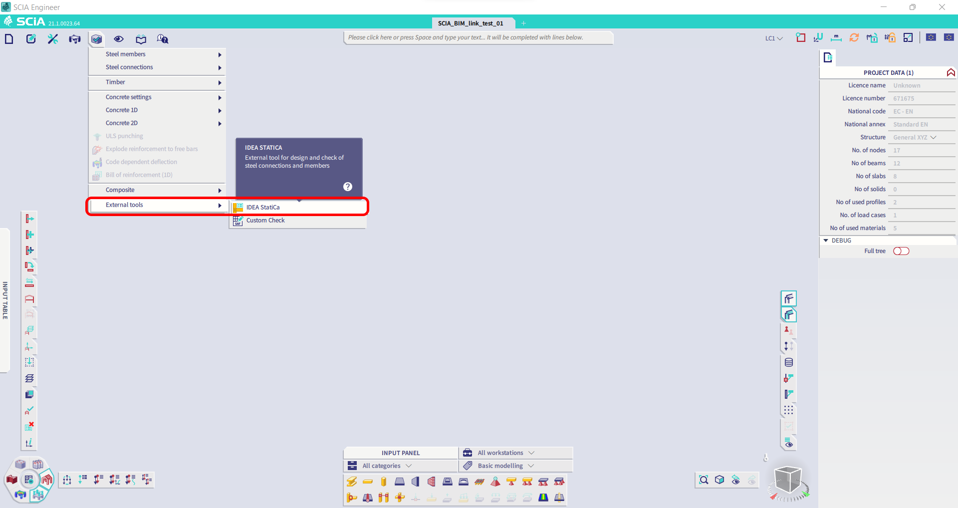
Ograniczenie: Ta funkcja nie jest dostępna w wersji Legacy SCIA 21.1.
Obejście: Należy używać domyślnego interfejsu użytkownika SCIA 21.1.
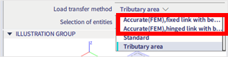
Ograniczenie: SCIA nie jest w stanie utworzyć pliku SAF używanego do komunikacji przez Bimlink. Problem objawia się następującym błędem w Checkbot oraz następującym komunikatem podczas bezpośredniego eksportu modelu SAF z SCIA.

Obejście: Aby to naprawić, należy zmienić wybór metody transferu z Tributary Area na Accurate (FEM).
WAŻNA UWAGA: W wersji Scia Engineer 26.0 eksport do formatu SAF został naprawiony i komunikat o błędzie wyświetlany powyżej nie pojawia się już więcej.
Ograniczenie: Kombinacje standardowe nie mogą być importowane do aplikacji IDEA StatiCa Checkbot.
Obejście: W SCIA Engineer należy rozłożyć kombinacje na obwiednie lub kombinacje liniowe przed eksportem.

Ograniczenie: Elementy z typem LCS innym niż „Standard" powodują niepowodzenie eksportu do Checkbot.
Obejście: Gdy podczas importu do Checkbot pojawi się następujący błąd:
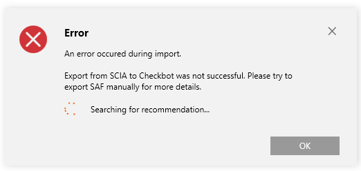
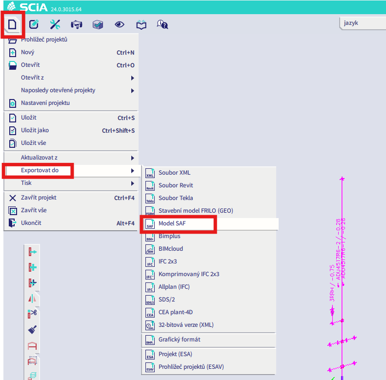
Należy przejść do SCIA i wykonać ręczny eksport pliku SAF.
Jeśli eksport nie powiedzie się, należy kliknąć „INFO" – górne wiersze informują o elementach, które używają innego LCS niż „standard".
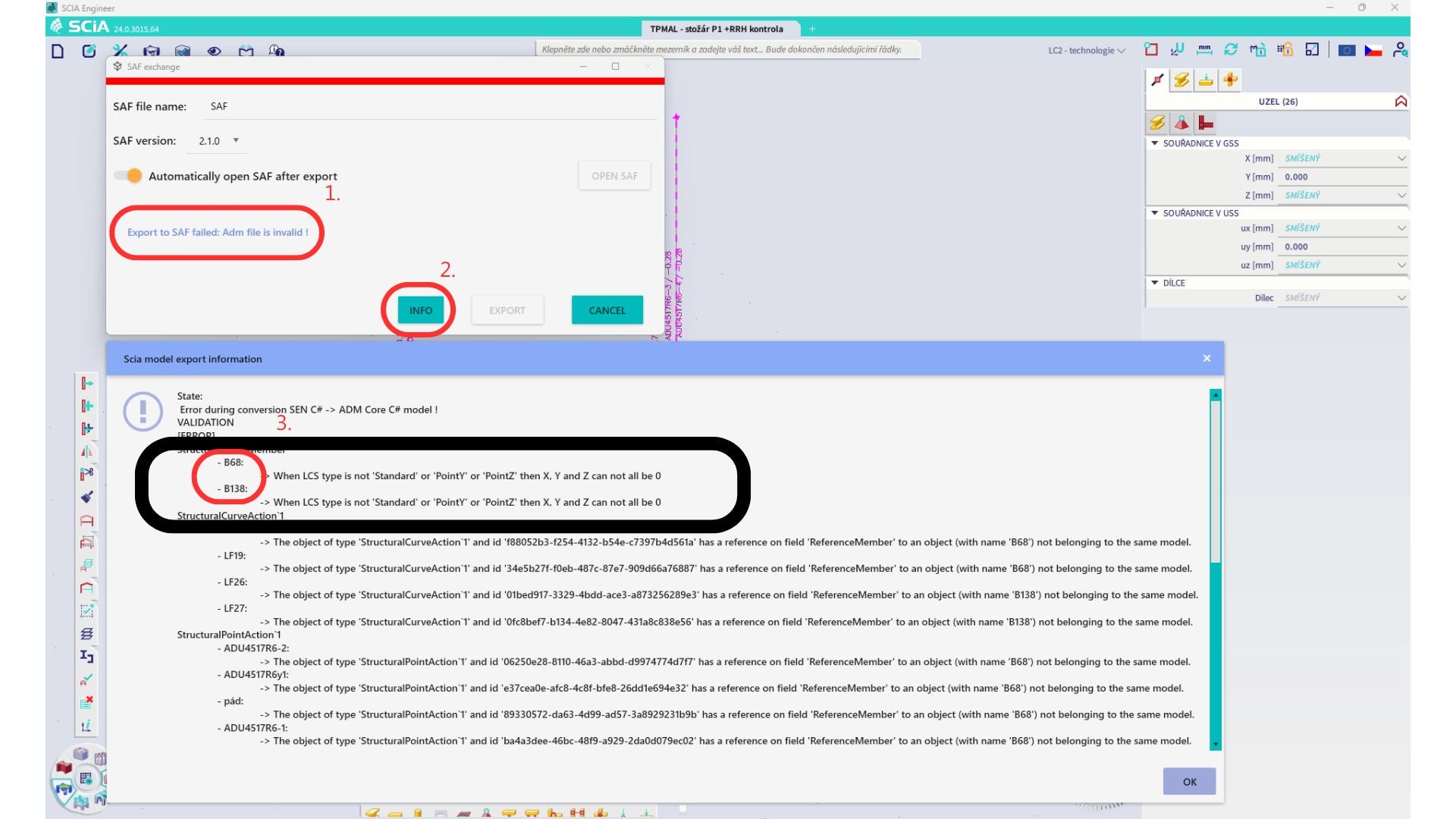
Należy zlokalizować te elementy i zmienić ich LCS na „standard". Następnie należy ponownie obliczyć model i uruchomić łącze BIM.
Ograniczenie: Kombinacje obwiedniowe w Scia Engineer zawierające przypadki obciążeń z zdefiniowanym „Master load case" nie są poprawnie łączone po imporcie do aplikacji IDEA StatiCa Checkbot z powodu brakujących informacji w pliku SAF.
Obejście: Przed eksportem należy rozłożyć kombinacje obwiedniowe zawarte w SCIA Engineer i zawierające przypadki obciążeń z zdefiniowanym „Master load case" na kombinacje liniowe.

Ograniczenie: Relacja Together w grupie obciążeń nie jest uwzględniana po imporcie do aplikacji IDEA StatiCa Checkbot i powoduje niespójność sił wewnętrznych między Scia Engineer a Checkbot.

Obejście: Przed eksportem należy rozłożyć kombinacje obwiedniowe na kombinacje liniowe w Scia Engineer. Drugim sposobem jest użycie bezpośredniego łącza do IDEA StatiCa Connection.