
SCIA Engineer BIM link for connection design (old)
1 How to activate the link
- Download and install (as administrator) the latest version of IDEA StatiCa
- Make sure that you are using the supported version of SCIA Engineer
IDEA StatiCa automatically integrates the BIM link into your CAD/CAE software during its installation. You can check the status and activate more BIM links for later installed software in the BIM link installer.
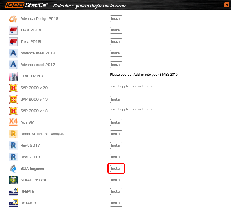
Open IDEA StatiCa and navigate to the panel BIM and open the BIM link installer. A notification "Run as administrator" may appear, please confirm with the Yes button.

Select the software to integrate the IDEA StatiCa BIM link, click the Install button and check the Installed status.
2 How to use the link
Download the attached project, open it in SCIA Engineer, and run the linear analysis to get the internal forces over the structure.
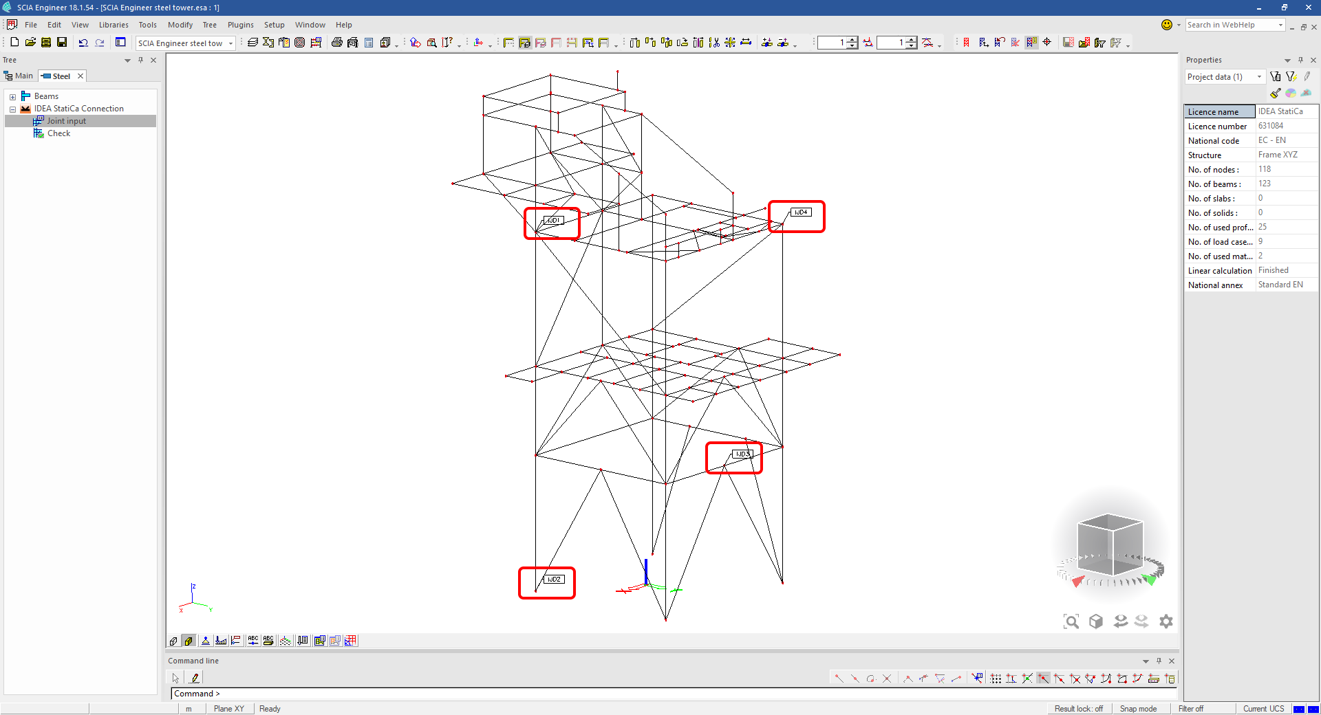
In the Main menu, go to the tab Steel.

Go to the IDEA StatiCa Connection menu. Add a joint to this SCIA Engineer project list of joints by selecting the members of a joint, then by clicking on Joint input and typing the name of it (name of the IDEA StatiCa Connection project file) and OK.

Open the command Check, run the command Export to IDEA Statica Connection in the Actions menu, and select the joint sign in the workspace.

Application IDEA StatiCa Connection opens and you can design connections of the joint.
3 Design
Joint geometry and load effects have been imported, you can start designing.

You will define a set of manufacturing operations to model connections between members. Hide the Load effects tree and right-click on Operations to add a new operation Cut.


In the next step add another manufacturing operation Endplate and modify its parameters.


Then add a Connecting plate operation and set its parameters for the appropriate member.


Right-click on the tongue plate, open the plate Editor and reshape the Tongue by adding an operation Rounding.


Next, you will again right-click on the gusset plate and in the Editor reshape the Gusset plate by adding a Bevel operation.


Now you can add a Stiffener operation and modify its properties.


Add another Cut operation for the upper member.


Again, use the Cut operation for the diagonals.


Copy the last cut operation and set it for the other diagonal.


In the next step add a Stiffener to the main column.


Finish the design by adding a Fin plate operation to connect the last member.


4 Check
You can start the analysis by clicking Calculate in the ribbon. The analysis model is automatically generated, the calculation is performed for all the load cases and you can see the Overall check displayed together with basic values of check results.

Go to the display tab Check and there activate Equivalent stress, Bolt forces, Mesh and Deformed and change the deformation scale in the ribbon to get a full picture of what is happening in the joint.

By default, you can see the For extreme results envelope of all the load effects, so the most unfavorable results are displayed all together. If you click on any item (e.g. the fin plate), it shows you which load effect is the most unfavorable for it in the ribbon.

You can also display and browse results for each load effect separately by changing the For the extreme option to For current in the ribbon.

5 Report
At last, go to the tab Report. IDEA StatiCa offers a fully customizable report to print out or save in an editable format.


You have imported a joint from SCIA Engineer and designed and code-checked it according to Eurocode.
6 How to update the project
Save the project and close the application Connection. All joints exported from an SCIA Engineer project to IDEA StatiCa are kept on the list as a part of the SCIA Engineer project file for later updates.
Note: In case you need to send a simple IDEA StatiCa file, you can "save as" a copy of the opened joint model to the desired folder
Go back to the SCIA Engineer model, change the cross-section of one of the diagonals, and start the Calculation of linear analysis again.

Open again the command Check, run the command Export to IDEA StatiCa Connection in the Actions menu, and select the joint sign in the workspace.

IDEA StatiCa opens and you can see the updated geometry while the design and settings adjust to the new state.

You can adjust the design, recalculate the joint code-check and save the project in IDEA StatiCa again and continue with exporting other joints.
Limitaciones conocidas para SCIA Engineer
Limitación: Las combinaciones no lineales no se pueden importar a la aplicación IDEA StatiCa Checkbot.
Limitación: La rotación de elementos mediante "α" no se puede importar desde SCIA Engineer a Checkbot
Solución alternativa: Rote el elemento usando "LCS Rotation" en su lugar; la rotación de los elementos se importará correctamente.

Limitación: Las cartelas modeladas en SCIA Engineer no se importan a Checkbot.
Solución alternativa: Las cartelas deben modelarse por separado en IDEA StatiCa Connection mediante Operaciones.

Limitación: La excentricidad modelada mediante "member system-line at" no se importa en la versión 25.0 y anteriores. A partir de la versión 25.1.0, esta limitación ha sido eliminada y los elementos se importan con la línea de sistema definida.
Solución alternativa: La excentricidad debe definirse mediante un valor ez o ey. La línea de sistema del elemento debe establecerse en "Centre".

Con la versión 21.1 de SCIA Engineer, IDEA StatiCa introdujo otra opción para utilizar el enlace BIM entre SCIA Engineer y la aplicación Checkbot.
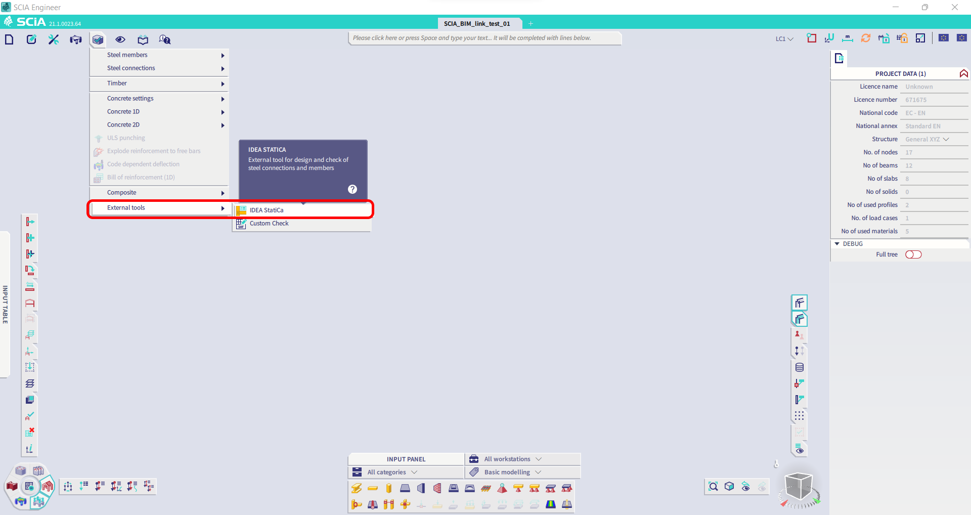
Limitación: Esta función no está integrada en la versión Legacy de SCIA 21.1.
Solución alternativa: Use la interfaz de usuario predeterminada de SCIA 21.1.
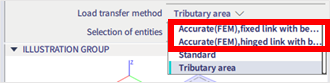
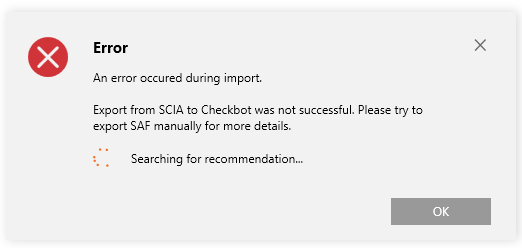
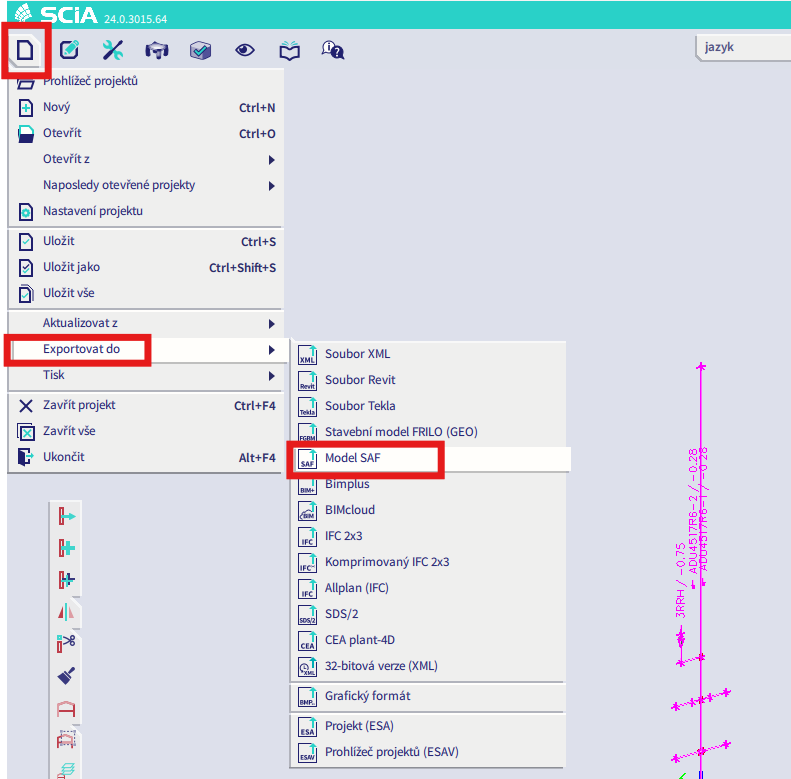
Limitación: SCIA no puede crear un archivo SAF utilizado para la comunicación Bimlink. El problema se manifiesta con el siguiente error en Checkbot y el siguiente mensaje al exportar el modelo SAF directamente desde SCIA.

Solución alternativa: Para solucionarlo, cambie la selección del método de transferencia de Tributary Area a Accurate (FEM).
NOTA IMPORTANTE: En la versión Scia Engineer 26.0, la exportación al SAF fue corregida y el mensaje de error mostrado anteriormente ya no aparece.
Limitación: Las combinaciones estándar no se pueden importar a la aplicación IDEA StatiCa Checkbot.
Solución alternativa: En SCIA Engineer, descomponga las combinaciones en envolventes o combinaciones lineales antes de exportar.

Limitación: Los elementos con un tipo de LCS distinto de "Standard" provocan que la exportación a Checkbot falle.
Solución alternativa: Cuando aparezca el siguiente error durante una importación a Checkbot.
Navegue a SCIA y realice una exportación manual del archivo SAF.
Si la exportación falla, haga clic en "INFO" y las líneas superiores le informarán sobre los elementos que utilizan un LCS distinto de "standard".
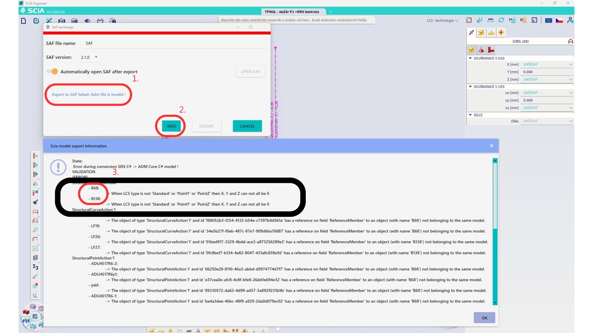
Localice los elementos y cambie su LCS a "standard". Recalcule y vuelva a iniciar el enlace BIM.
Limitación: Las combinaciones envolventes en Scia Engineer que contienen casos de carga con un "Master load case" definido no se combinan correctamente tras la importación en la aplicación IDEA StatiCa Checkbot debido a información faltante en el archivo SAF.
Solución alternativa: Antes de exportar, descomponga las combinaciones envolventes contenidas en SCIA Engineer que incluyan casos de carga con un "Master load case" definido en combinaciones lineales.

Limitación: La relación Together en el grupo de cargas no se tiene en cuenta tras la importación en la aplicación IDEA StatiCa Checkbot y provoca fuerzas internas inconsistentes entre Scia Engineer y Checkbot.

Solución alternativa: Antes de exportar, descomponga las combinaciones envolventes en combinaciones lineales en Scia Engineer. La segunda opción es utilizar el enlace directo a IDEA StatiCa Connection.