
SCIA Engineer BIM link for connection design (old)
1 How to activate the link
- Download and install (as administrator) the latest version of IDEA StatiCa
- Make sure that you are using the supported version of SCIA Engineer
IDEA StatiCa automatically integrates the BIM link into your CAD/CAE software during its installation. You can check the status and activate more BIM links for later installed software in the BIM link installer.
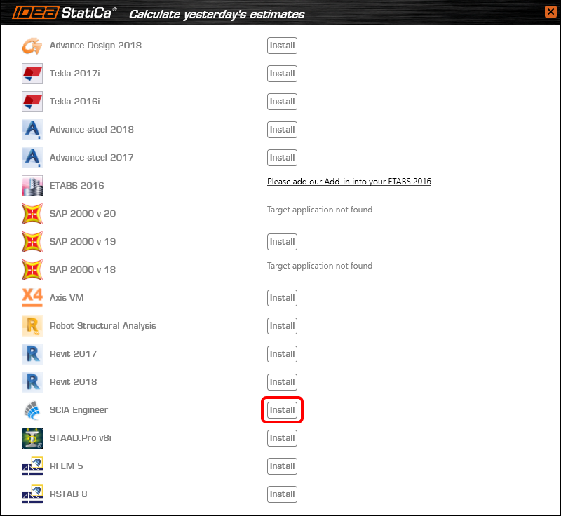
Open IDEA StatiCa and navigate to the panel BIM and open the BIM link installer. A notification "Run as administrator" may appear, please confirm with the Yes button.

Select the software to integrate the IDEA StatiCa BIM link, click the Install button and check the Installed status.
2 How to use the link
Download the attached project, open it in SCIA Engineer, and run the linear analysis to get the internal forces over the structure.
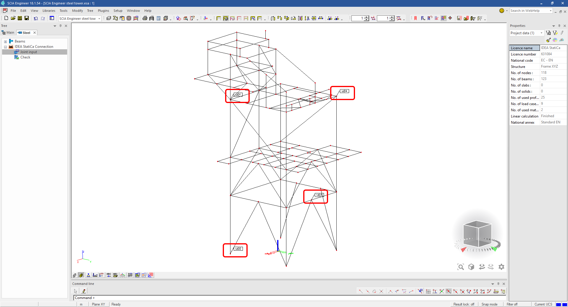
In the Main menu, go to the tab Steel.

Go to the IDEA StatiCa Connection menu. Add a joint to this SCIA Engineer project list of joints by selecting the members of a joint, then by clicking on Joint input and typing the name of it (name of the IDEA StatiCa Connection project file) and OK.

Open the command Check, run the command Export to IDEA Statica Connection in the Actions menu, and select the joint sign in the workspace.

Application IDEA StatiCa Connection opens and you can design connections of the joint.
3 Design
Joint geometry and load effects have been imported, you can start designing.

You will define a set of manufacturing operations to model connections between members. Hide the Load effects tree and right-click on Operations to add a new operation Cut.


In the next step add another manufacturing operation Endplate and modify its parameters.


Then add a Connecting plate operation and set its parameters for the appropriate member.


Right-click on the tongue plate, open the plate Editor and reshape the Tongue by adding an operation Rounding.


Next, you will again right-click on the gusset plate and in the Editor reshape the Gusset plate by adding a Bevel operation.


Now you can add a Stiffener operation and modify its properties.


Add another Cut operation for the upper member.


Again, use the Cut operation for the diagonals.


Copy the last cut operation and set it for the other diagonal.


In the next step add a Stiffener to the main column.


Finish the design by adding a Fin plate operation to connect the last member.


4 Check
You can start the analysis by clicking Calculate in the ribbon. The analysis model is automatically generated, the calculation is performed for all the load cases and you can see the Overall check displayed together with basic values of check results.

Go to the display tab Check and there activate Equivalent stress, Bolt forces, Mesh and Deformed and change the deformation scale in the ribbon to get a full picture of what is happening in the joint.

By default, you can see the For extreme results envelope of all the load effects, so the most unfavorable results are displayed all together. If you click on any item (e.g. the fin plate), it shows you which load effect is the most unfavorable for it in the ribbon.

You can also display and browse results for each load effect separately by changing the For the extreme option to For current in the ribbon.

5 Report
At last, go to the tab Report. IDEA StatiCa offers a fully customizable report to print out or save in an editable format.


You have imported a joint from SCIA Engineer and designed and code-checked it according to Eurocode.
6 How to update the project
Save the project and close the application Connection. All joints exported from an SCIA Engineer project to IDEA StatiCa are kept on the list as a part of the SCIA Engineer project file for later updates.
Note: In case you need to send a simple IDEA StatiCa file, you can "save as" a copy of the opened joint model to the desired folder
Go back to the SCIA Engineer model, change the cross-section of one of the diagonals, and start the Calculation of linear analysis again.

Open again the command Check, run the command Export to IDEA StatiCa Connection in the Actions menu, and select the joint sign in the workspace.

IDEA StatiCa opens and you can see the updated geometry while the design and settings adjust to the new state.

You can adjust the design, recalculate the joint code-check and save the project in IDEA StatiCa again and continue with exporting other joints.
ข้อจำกัดที่ทราบสำหรับ SCIA Engineer
ข้อจำกัด: การรวมแรงแบบไม่เชิงเส้นไม่สามารถนำเข้าสู่แอปพลิเคชัน IDEA StatiCa Checkbot ได้
ข้อจำกัด: การหมุนชิ้นส่วนโดยใช้ "α" ไม่สามารถนำเข้าจาก SCIA Engineer ไปยัง Checkbot ได้
วิธีแก้ไข: ให้หมุนชิ้นส่วนโดยใช้ "LCS Rotation" แทน การหมุนชิ้นส่วนจะถูกนำเข้าได้อย่างถูกต้อง

ข้อจำกัด: ส่วนเสริมคาน (Haunches) ที่สร้างแบบจำลองใน SCIA Engineer จะไม่ถูกนำเข้าสู่ Checkbot
วิธีแก้ไข: ส่วนเสริมคานต้องสร้างแบบจำลองแยกต่างหากใน IDEA StatiCa Connection โดยใช้ Operations

ข้อจำกัด: ความเยื้องศูนย์ที่สร้างแบบจำลองโดยใช้ "member system-line at" จะไม่ถูกนำเข้าในเวอร์ชัน 25.0 และเก่ากว่า ตั้งแต่เวอร์ชัน 25.1.0 ข้อจำกัดนี้ได้ถูกยกเลิกแล้ว และชิ้นส่วนจะถูกนำเข้าพร้อมกับเส้นระบบที่กำหนดไว้
วิธีแก้ไข: ความเยื้องศูนย์ต้องกำหนดผ่านค่า ez หรือ ey โดยต้องตั้งค่าเส้นระบบของชิ้นส่วนเป็น "Centre"

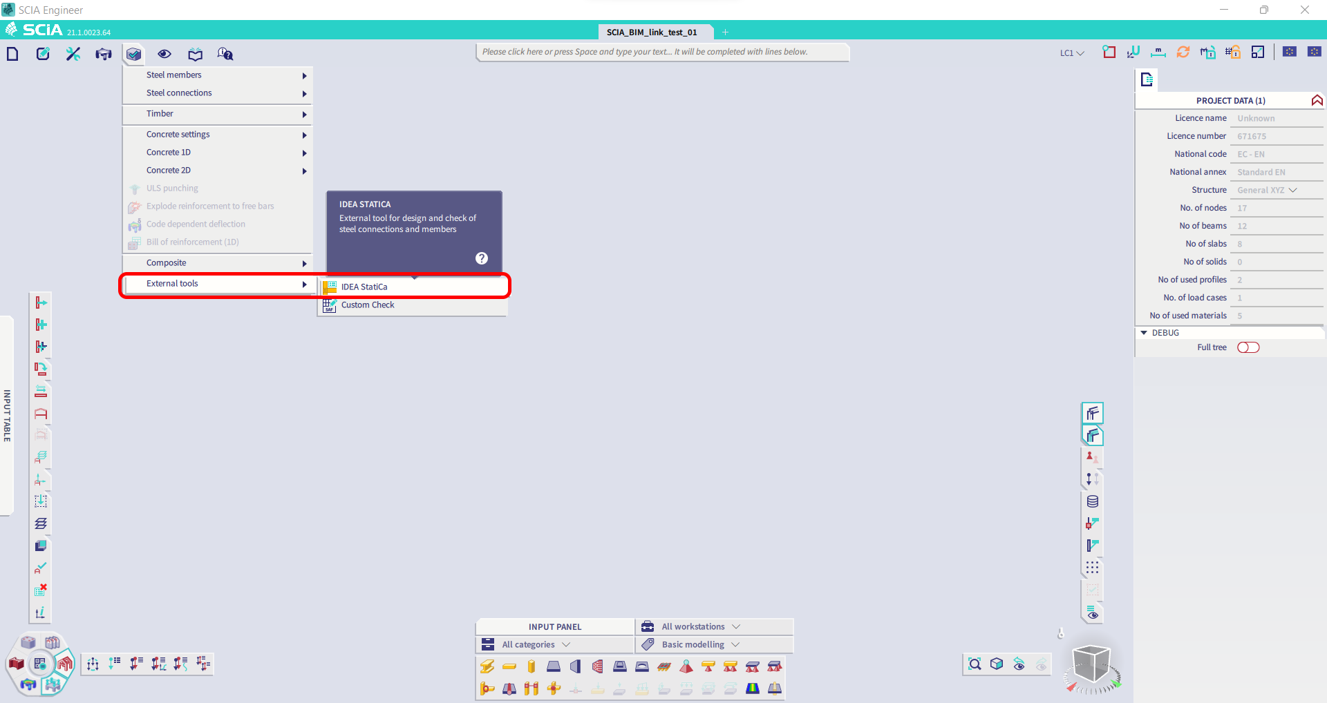
ด้วย SCIA Engineer เวอร์ชัน 21.1 IDEA StatiCa ได้แนะนำตัวเลือกเพิ่มเติมสำหรับการใช้งาน BIM link ระหว่าง SCIA Engineer และแอปพลิเคชัน Checkbot
ข้อจำกัด: ฟีเจอร์นี้ไม่ได้ฝังอยู่ในเวอร์ชัน Legacy ของ SCIA 21.1
วิธีแก้ไข: ใช้ UX เริ่มต้นของ SCIA 21.1
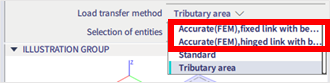
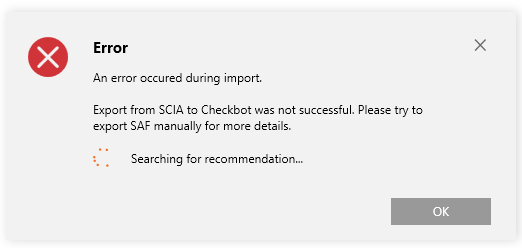
ข้อจำกัด: SCIA ไม่สามารถสร้างไฟล์ SAF ที่ใช้สำหรับการสื่อสาร Bimlink ได้ ปัญหานี้แสดงตัวเองด้วยข้อผิดพลาดต่อไปนี้ใน Checkbot และข้อความต่อไปนี้เมื่อส่งออกโมเดล SAF โดยตรงจาก SCIA

วิธีแก้ไข: เพื่อแก้ไขปัญหานี้ ให้เปลี่ยนการเลือกวิธีการถ่ายแรงจาก Tributary Area เป็น Accurate (FEM).
หมายเหตุสำคัญ: ในเวอร์ชัน Scia Engineer 26.0 การส่งออกไปยัง SAF ได้รับการแก้ไขแล้ว และข้อความแสดงข้อผิดพลาดที่แสดงด้านบนจะไม่ปรากฏอีกต่อไป
ข้อจำกัด: การรวมแรงมาตรฐานไม่สามารถนำเข้าสู่แอปพลิเคชัน IDEA StatiCa Checkbot ได้
วิธีแก้ไข: ใน SCIA Engineer ให้แยกการรวมแรงออกเป็น Envelopes หรือการรวมแรงเชิงเส้นก่อนส่งออก

ข้อจำกัด: ชิ้นส่วนที่มีประเภท LCS อื่นนอกจาก "Standard" ทำให้การส่งออกไปยัง Checkbot ล้มเหลว
วิธีแก้ไข: เมื่อข้อผิดพลาดต่อไปนี้ปรากฏขึ้นระหว่างการนำเข้าสู่ Checkbot
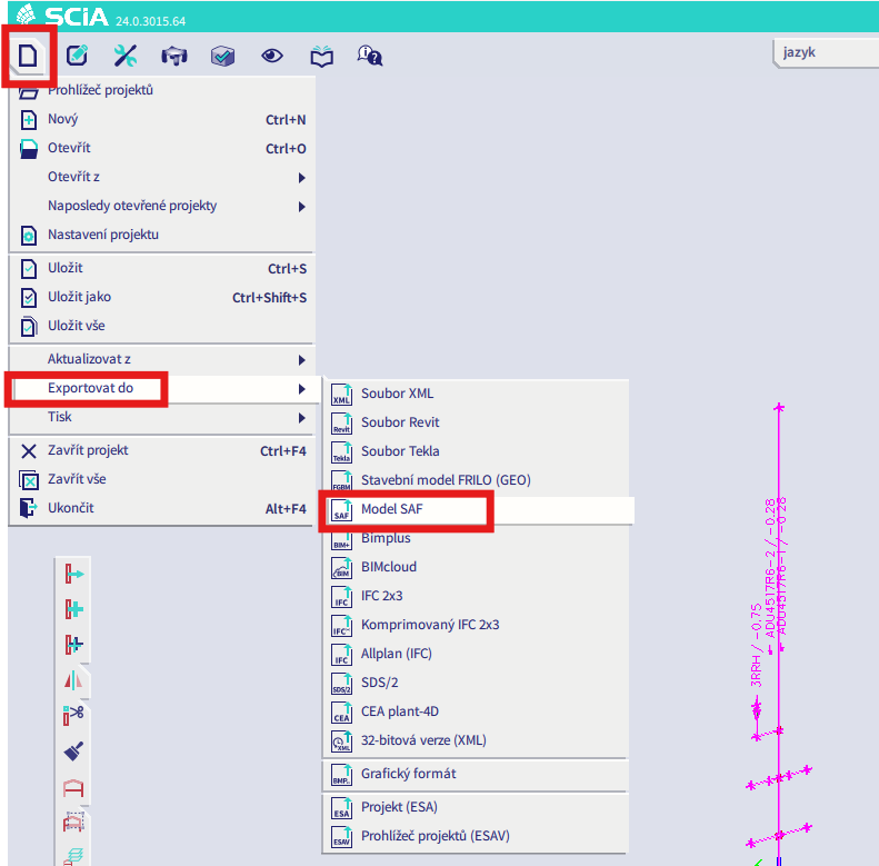
ไปที่ SCIA และทำการส่งออกไฟล์ SAF ด้วยตนเอง
หากการส่งออกล้มเหลว ให้คลิกที่ "INFO" และบรรทัดบนสุดจะแจ้งให้คุณทราบเกี่ยวกับชิ้นส่วนที่ใช้ LCS อื่นนอกจาก "standard"
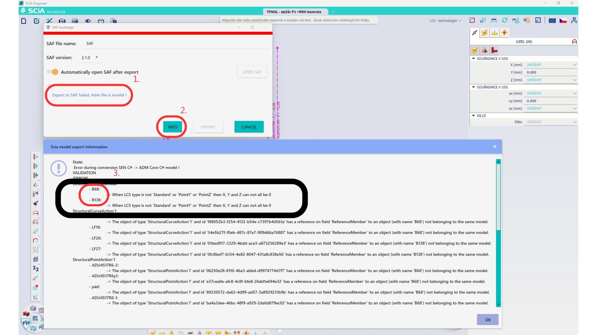
ค้นหาชิ้นส่วนเหล่านั้นและเปลี่ยน LCS เป็น "standard" จากนั้นคำนวณใหม่และเปิดใช้งาน BIM link อีกครั้ง
ข้อจำกัด: การรวมแรงแบบ Envelope ใน Scia Engineer ที่มีกรณีแรงกระทำซึ่งกำหนด "Master load case" ไว้จะไม่ถูกรวมอย่างถูกต้องหลังจากนำเข้าสู่แอปพลิเคชัน IDEA StatiCa Checkbot เนื่องจากข้อมูลที่ขาดหายไปในไฟล์ SAF
วิธีแก้ไข: ก่อนส่งออก ให้แยกการรวมแรงแบบ Envelope ที่อยู่ใน SCIA Engineer และมีกรณีแรงกระทำที่กำหนด "Master load case" ออกเป็นการรวมแรงเชิงเส้น

ข้อจำกัด: ความสัมพันธ์ Together ใน Load group จะไม่ถูกนำมาพิจารณาหลังจากนำเข้าสู่แอปพลิเคชัน IDEA StatiCa Checkbot และทำให้เกิดความไม่สอดคล้องของแรงภายในระหว่าง Scia Engineer และ Checkbot

วิธีแก้ไข: ก่อนส่งออก ให้แยก การรวมแรงแบบ Envelope ออกเป็นการรวมแรงเชิงเส้นใน Scia Engineer วิธีที่สองคือใช้ลิงก์โดยตรงไปยัง IDEA StatiCa Connection