
SCIA Engineer BIM link for connection design (old)
1 How to activate the link
- Download and install (as administrator) the latest version of IDEA StatiCa
- Make sure that you are using the supported version of SCIA Engineer
IDEA StatiCa automatically integrates the BIM link into your CAD/CAE software during its installation. You can check the status and activate more BIM links for later installed software in the BIM link installer.
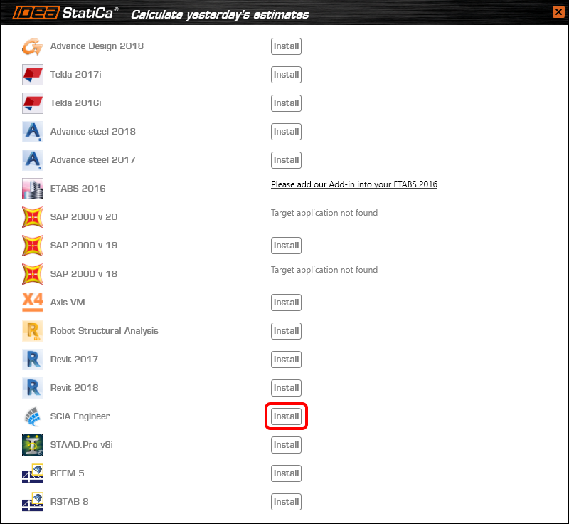
Open IDEA StatiCa and navigate to the panel BIM and open the BIM link installer. A notification "Run as administrator" may appear, please confirm with the Yes button.

Select the software to integrate the IDEA StatiCa BIM link, click the Install button and check the Installed status.
2 How to use the link
Download the attached project, open it in SCIA Engineer, and run the linear analysis to get the internal forces over the structure.
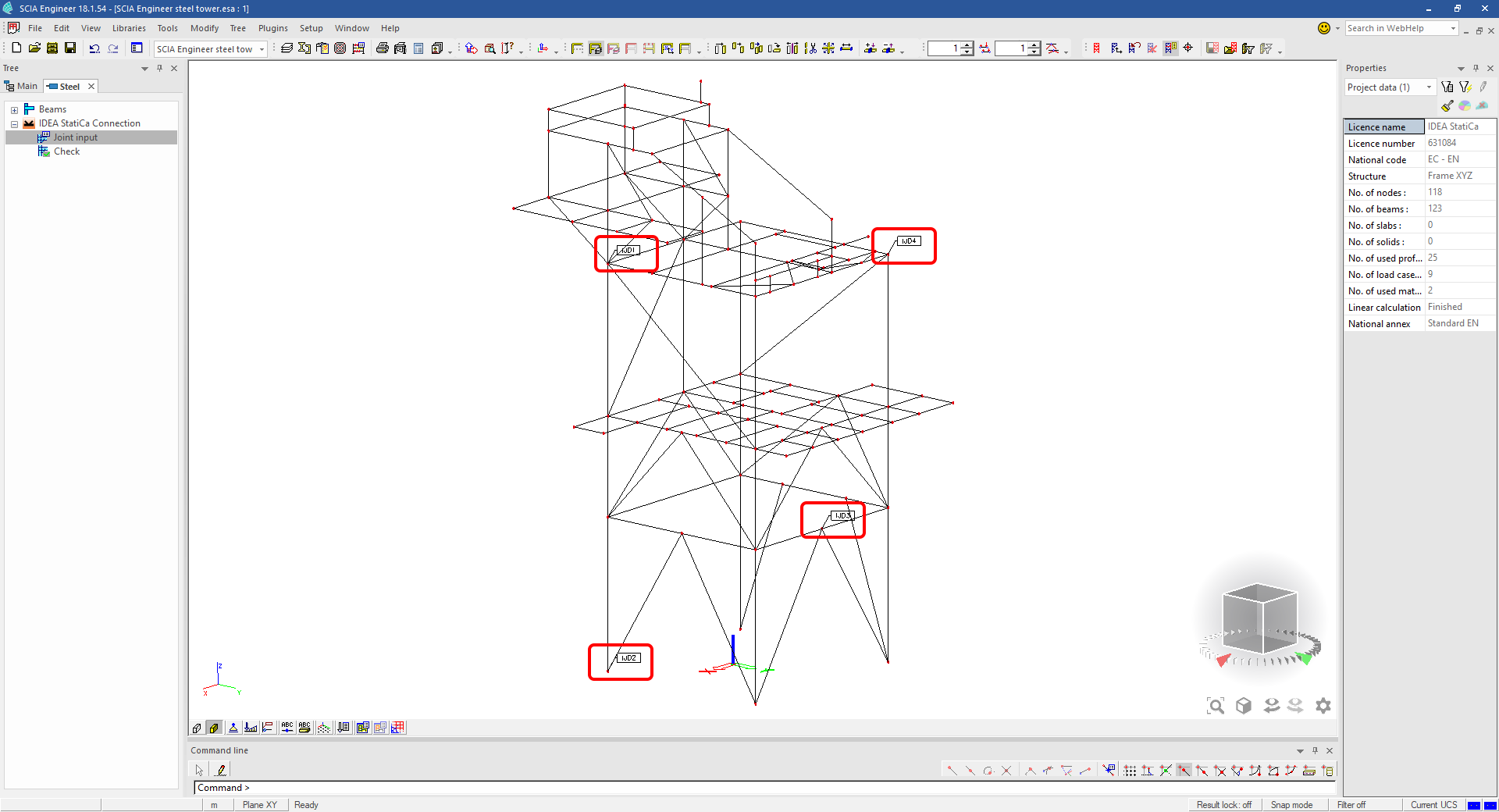
In the Main menu, go to the tab Steel.

Go to the IDEA StatiCa Connection menu. Add a joint to this SCIA Engineer project list of joints by selecting the members of a joint, then by clicking on Joint input and typing the name of it (name of the IDEA StatiCa Connection project file) and OK.

Open the command Check, run the command Export to IDEA Statica Connection in the Actions menu, and select the joint sign in the workspace.

Application IDEA StatiCa Connection opens and you can design connections of the joint.
3 Design
Joint geometry and load effects have been imported, you can start designing.

You will define a set of manufacturing operations to model connections between members. Hide the Load effects tree and right-click on Operations to add a new operation Cut.


In the next step add another manufacturing operation Endplate and modify its parameters.


Then add a Connecting plate operation and set its parameters for the appropriate member.


Right-click on the tongue plate, open the plate Editor and reshape the Tongue by adding an operation Rounding.


Next, you will again right-click on the gusset plate and in the Editor reshape the Gusset plate by adding a Bevel operation.


Now you can add a Stiffener operation and modify its properties.


Add another Cut operation for the upper member.


Again, use the Cut operation for the diagonals.


Copy the last cut operation and set it for the other diagonal.


In the next step add a Stiffener to the main column.


Finish the design by adding a Fin plate operation to connect the last member.


4 Check
You can start the analysis by clicking Calculate in the ribbon. The analysis model is automatically generated, the calculation is performed for all the load cases and you can see the Overall check displayed together with basic values of check results.

Go to the display tab Check and there activate Equivalent stress, Bolt forces, Mesh and Deformed and change the deformation scale in the ribbon to get a full picture of what is happening in the joint.

By default, you can see the For extreme results envelope of all the load effects, so the most unfavorable results are displayed all together. If you click on any item (e.g. the fin plate), it shows you which load effect is the most unfavorable for it in the ribbon.

You can also display and browse results for each load effect separately by changing the For the extreme option to For current in the ribbon.

5 Report
At last, go to the tab Report. IDEA StatiCa offers a fully customizable report to print out or save in an editable format.


You have imported a joint from SCIA Engineer and designed and code-checked it according to Eurocode.
6 How to update the project
Save the project and close the application Connection. All joints exported from an SCIA Engineer project to IDEA StatiCa are kept on the list as a part of the SCIA Engineer project file for later updates.
Note: In case you need to send a simple IDEA StatiCa file, you can "save as" a copy of the opened joint model to the desired folder
Go back to the SCIA Engineer model, change the cross-section of one of the diagonals, and start the Calculation of linear analysis again.

Open again the command Check, run the command Export to IDEA StatiCa Connection in the Actions menu, and select the joint sign in the workspace.

IDEA StatiCa opens and you can see the updated geometry while the design and settings adjust to the new state.

You can adjust the design, recalculate the joint code-check and save the project in IDEA StatiCa again and continue with exporting other joints.
Limitations connues pour SCIA Engineer
Limitation : Les combinaisons non linéaires ne peuvent pas être importées dans l'application IDEA StatiCa Checkbot.
Limitation : La rotation des éléments à l'aide de "α" ne peut pas être importée de SCIA Engineer vers Checkbot
Workaround : Faites pivoter l'élément en utilisant "LCS Rotation" à la place, la rotation des éléments sera importée correctement.

Limitation : Les jarrets modélisés dans SCIA Engineer ne sont pas importés dans Checkbot.
Workaround : Les jarrets doivent être modélisés séparément dans IDEA StatiCa Connection à l'aide des opérations.

Limitation : L'excentricité modélisée à l'aide de "member system-line at" n'est pas importée dans la version 25.0 et les versions antérieures. À partir de la version 25.1.0, cette limitation a été supprimée et les éléments sont importés avec la ligne système définie.
Workaround : L'excentricité doit être définie via une valeur ez ou ey. La ligne système de l'élément doit être définie sur "Centre".

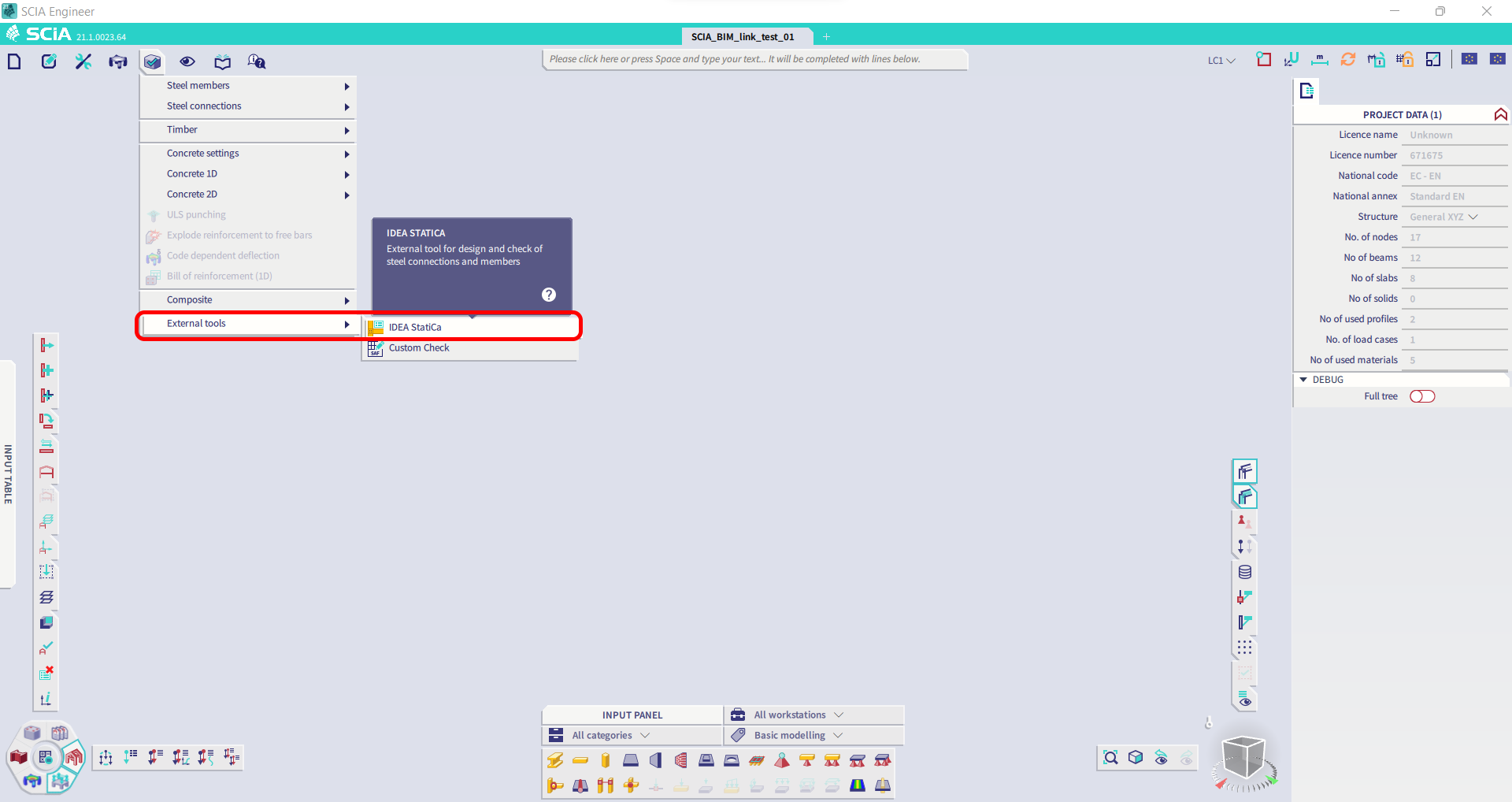
Avec la version 21.1 de SCIA Engineer, IDEA StatiCa a introduit une autre option d'utilisation du lien BIM entre SCIA Engineer et l'application Checkbot.
Limitation : Cette fonctionnalité n'est pas intégrée dans la version Legacy de SCIA 21.1.
Workaround : Utilisez l'interface utilisateur par défaut de SCIA 21.1.
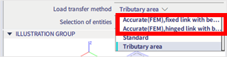
Limitation : SCIA est incapable de créer un fichier SAF utilisé pour la communication Bimlink. Le problème se manifeste par l'erreur suivante dans Checkbot et le message suivant lors de l'exportation du modèle SAF directement depuis SCIA.

Workaround : Pour y remédier, modifiez la sélection de la méthode de transfert de Tributary Area vers Accurate (FEM).
NOTE IMPORTANTE : Dans la version Scia Engineer 26.0, l'exportation vers le SAF a été corrigée et le message d'erreur affiché ci-dessus n'apparaît plus.
Limitation : Les combinaisons standard ne peuvent pas être importées dans l'application IDEA StatiCa Checkbot.
Workaround : Dans SCIA Engineer, décomposez les combinaisons en enveloppes ou en combinaisons linéaires avant l'exportation.

Limitation : Les éléments avec un type LCS autre que "Standard" provoquent l'échec de l'exportation vers Checkbot.
Workaround : Lorsque l'erreur suivante apparaît lors d'une importation dans Checkbot.
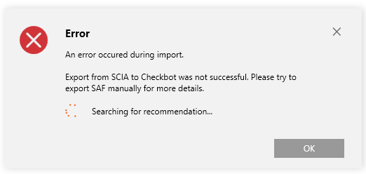
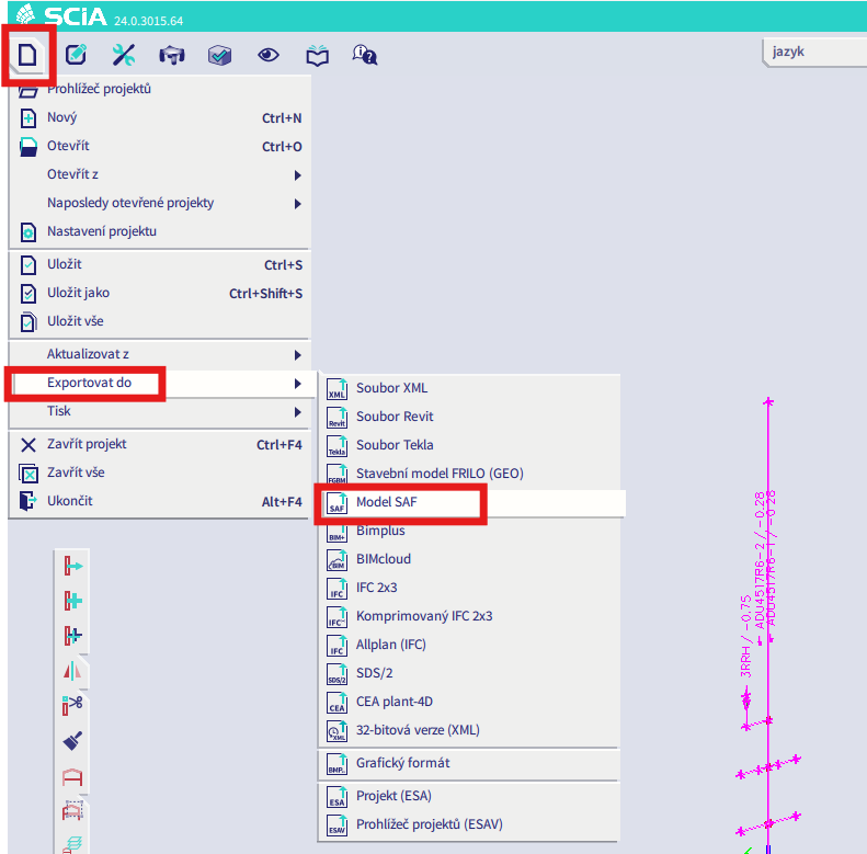
Accédez à SCIA et effectuez une exportation manuelle du fichier SAF.
Si l'exportation échoue, cliquez sur "INFO" et les premières lignes vous informent sur les éléments qui utilisent un LCS autre que "standard".
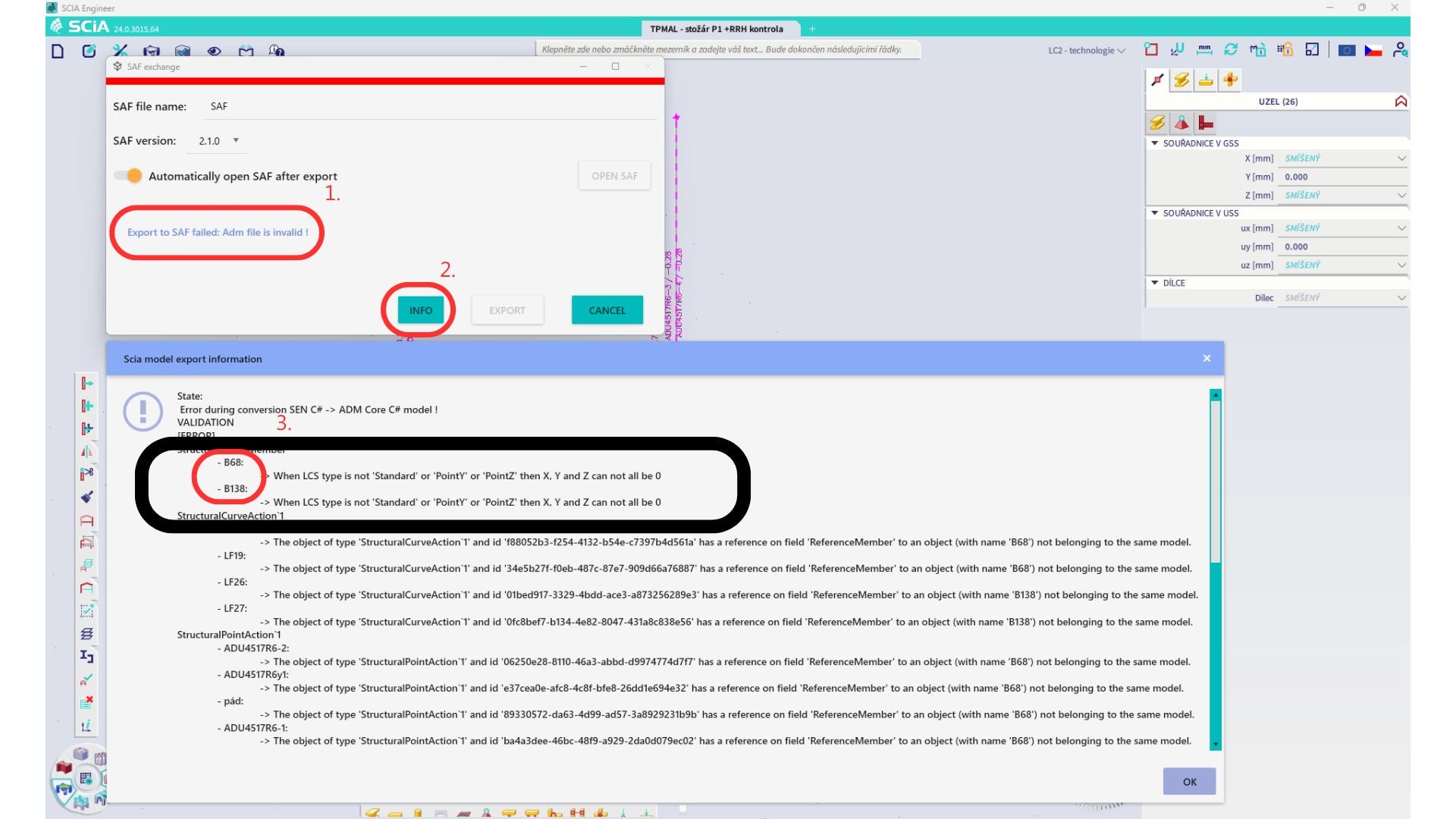
Localisez les éléments et modifiez leur LCS en "standard". Recalculez et relancez le lien BIM.
Limitation : Les combinaisons enveloppes dans Scia Engineer contenant des cas de charge avec un "cas de charge maître" défini ne sont pas combinées correctement après importation dans l'application IDEA StatiCa Checkbot en raison d'informations manquantes dans le fichier SAF.
Workaround : Avant l'exportation, décomposez les combinaisons enveloppes contenues dans SCIA Engineer et contenant des cas de charge avec un "cas de charge maître" défini en combinaisons linéaires.

Limitation : La relation Together dans le groupe de charges n'est pas prise en compte après importation dans l'application IDEA StatiCa Checkbot et provoque des efforts intérieurs incohérents entre Scia Engineer et Checkbot.

Workaround : Avant l'exportation, décomposez les combinaisons enveloppes en combinaisons linéaires dans Scia Engineer. La deuxième solution consiste à utiliser le lien direct vers IDEA StatiCa Connection.