
ETABS BIM link for steel connection design (AISC)
1 How to activate the link
- Install the latest version of IDEA StatiCa
- Make sure you are using a supported version of ETABS – updates are published in the BIM section of the main website
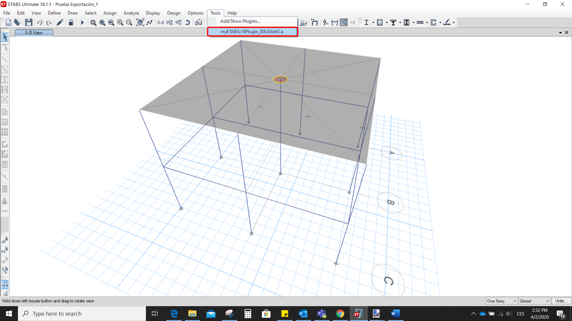
After installation of both programs, start ETABS and Click Tools > Add/Show Plugins to open the Plugin Manager dialog. This option lets you install and add add-ins (programs) to the appropriate places in the ETABS menu.
Browse for
C:\Program Files\IDEA StatiCa\StatiCa 20.0\ETABSv18PlugIn_IDEAStatiCa.dll
and click Add

2 How to use the link
Open the attached project in ETABS and run the analysis.
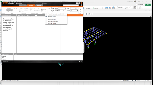
Go to the menu item Tools and run the export command you have just defined.
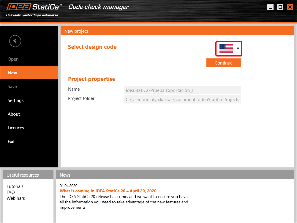
The Code-check manager opens and at first, you need to choose the code.
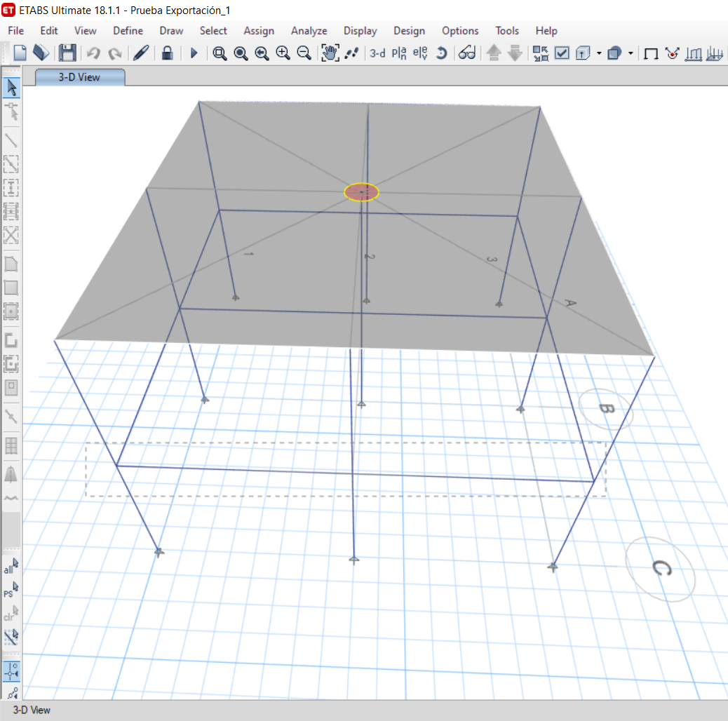
Then you can make a rectangular selection in the ETABS project to choose which joints you want to export. You can export more joints at once using the multiple selections.
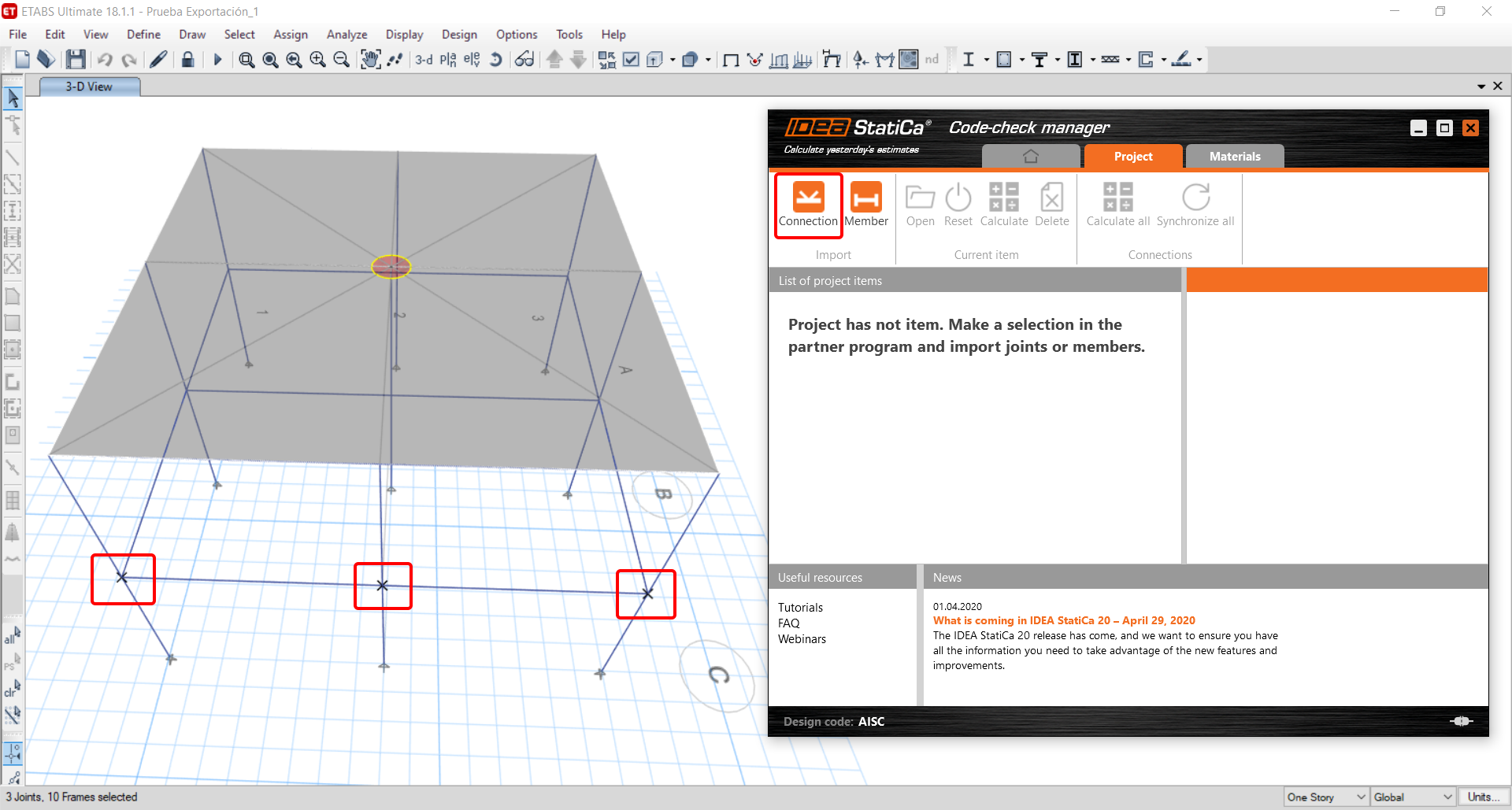
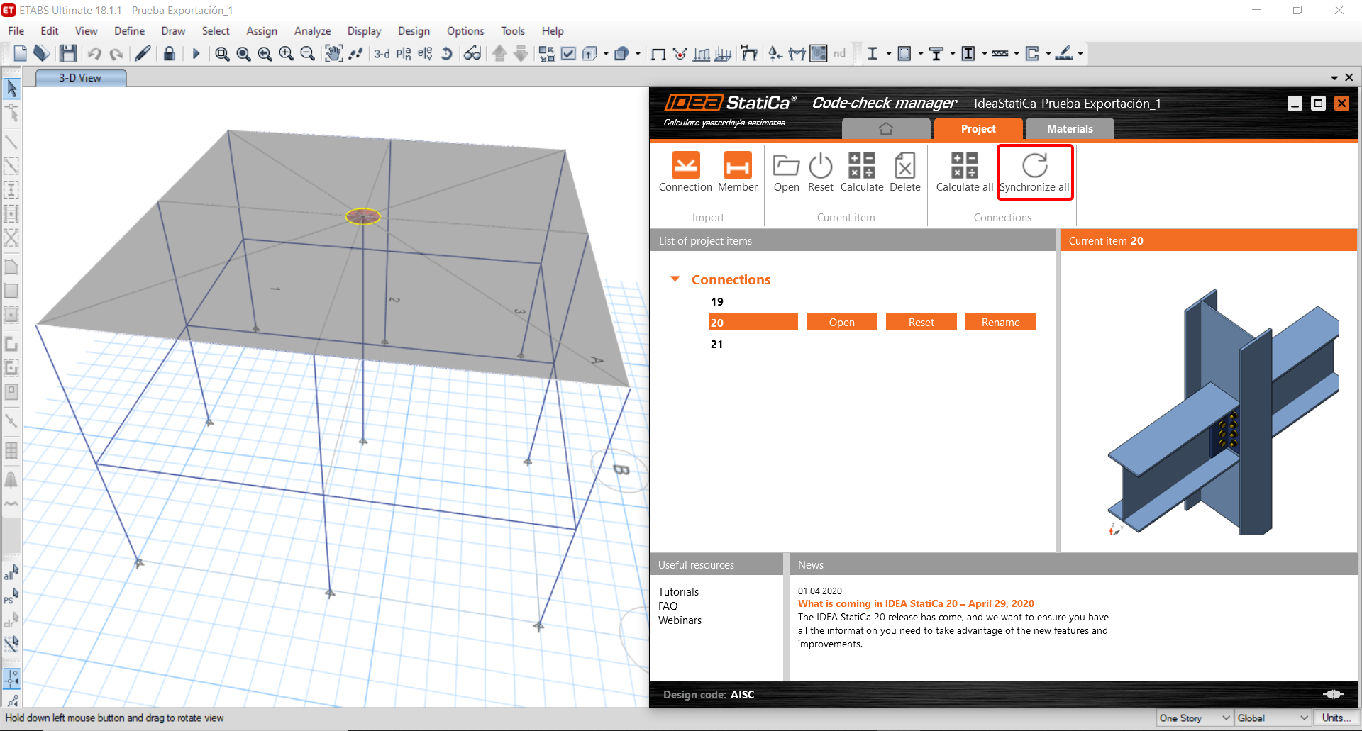
If the joints are selected, you can click on the Connection button in the Code-check manager. With this, all the selected joints from ETABS will be imported into the Code-check manager.
The next thing you need to do is to configure the joints in the Code-check manager. In this tutorial, you will only focus on one of the three imported joints, but the process would be the same for all of them.
You click on the joint on the left side (joint 20). On the right side, you can see the scheme of the joint, you can set the bearing member and merge the continuous members. After that, click on the Finish button to complete the configuration of the joint.
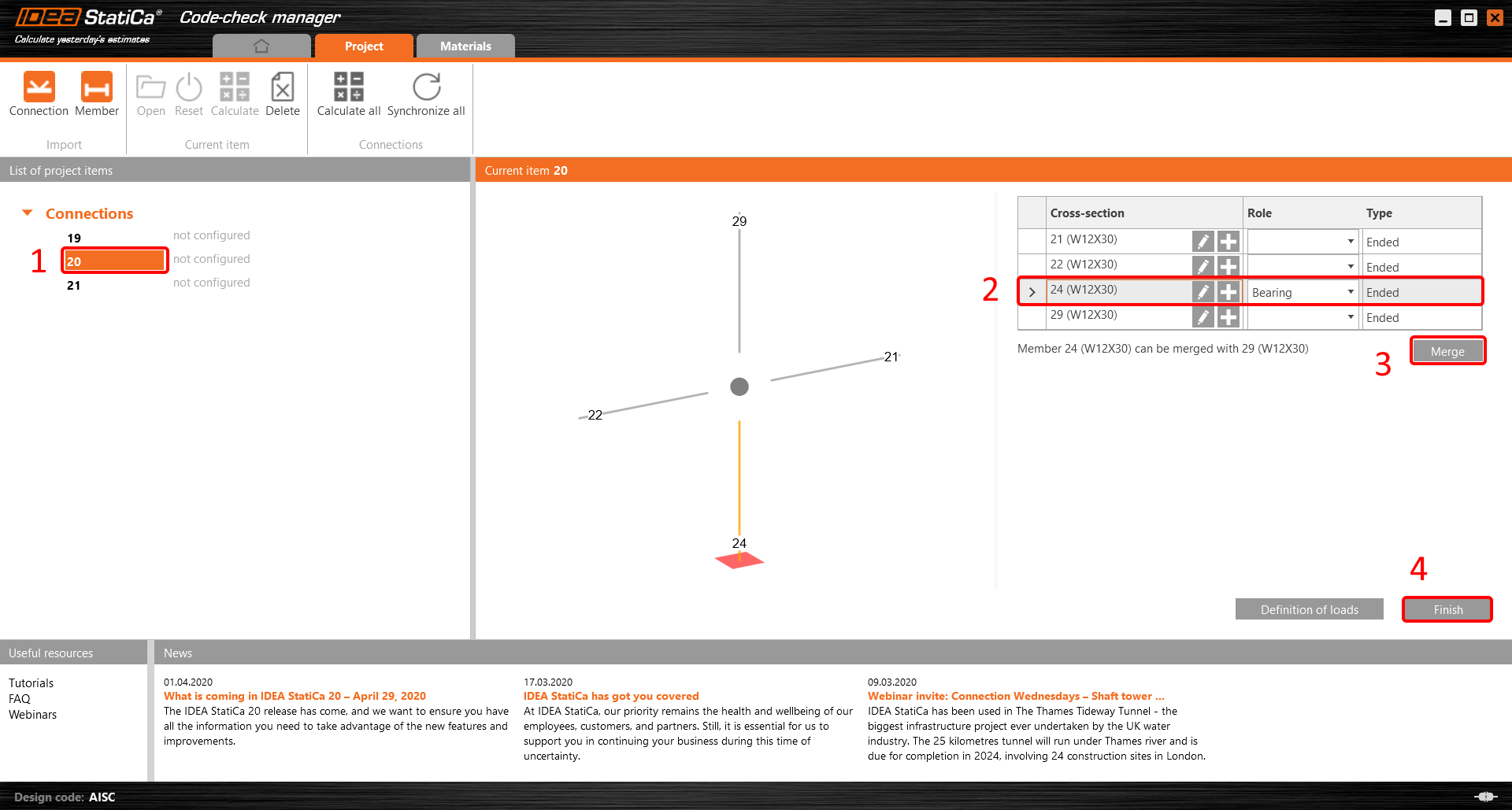
The joint is now ready to be opened in IDEA StatiCa Connection for the CBFEM analysis.

3 Design
Automatic data transfer is started and IDEA StatiCa Connection with a generated project is launched. All members and load effects were added automatically.
This tutorial works with imperial units. If you use metric units, you can switch them to imperial by clicking on the unit in the bottom part of the window.

Now you will define a set of manufacturing operations to model the connection between members. In the items tree, you right-click on Operations and select the option New operation.
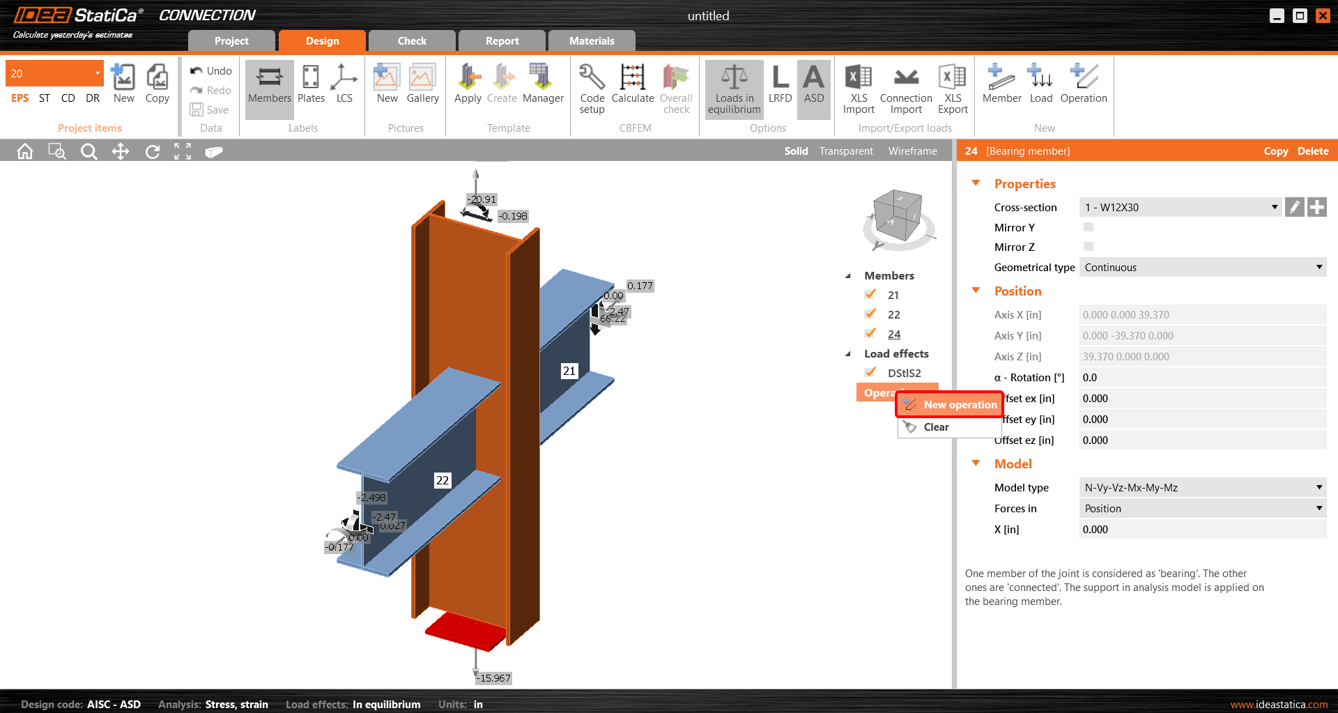
And you add the operation Cleat.


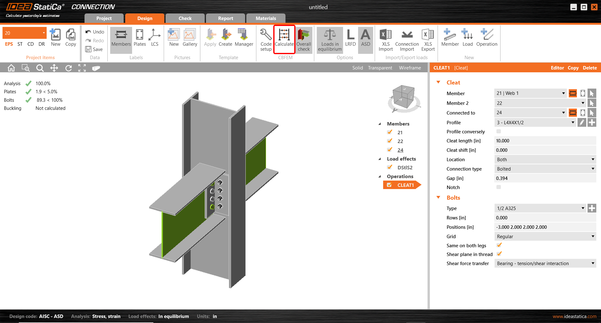
And set the properties of CLEAT1 as follows:

You can check the design of this simple joint.

4 Check
The analysis based on CBFEM is started by the icon Calculate from the top ribbon. The analysis model is automatically generated, the calculation is performed, and you can check the results.
Activate Overall check, Equivalent stress, Mesh and Deformed from the ribbon to get a full picture of what is happening in the joint. Everything is displayed in the 3D window.

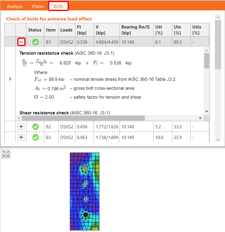
All values can be reviewed in detail in the tables and 2D windows. For example, to display the check of bolts, select the Bolts tab.
5 Report
At last, go to the tab Report. IDEA StatiCa offers a fully customizable report to print out or save in an editable format.

You have imported, designed, and code-checked a steel joint according to AISC.
6 Synchronize models
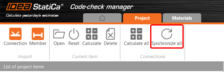
The Code-check manager is a BIM tool to export and synchronize connections from other programs. It is launched directly in the 3rd party applications via a command/icon.
Synchronize all - IDEA StatiCa detects changes in all already imported entities (changes in thickness, changes in cross-section, modification of properties of welds, bolts, etc.) and updates the project in IDEA StatiCa Connection.
Calculate - Synchronize and calculate the current item and provide a new set of results.
Calculate all - Synchronize and calculate all items and provide a new set of results.
Note
Kindly be aware that IDEA StatiCa syncs with a model of the 3rd party application, not the other way around.
Save the project in IDEA StatiCa and close the application Connection. All joints exported from the ETABS project to IDEA StatiCa are kept on the list inside ETABS.
Unlock the model and change the cross-section of member 22 from W12x30 to W12x26.

Run the analysis, select the export command in the upper ribbon, and in the Code-check manager, click on Synchronize.
In the next step, you can Open the joint in IDEA StatiCa Connection to explore the changes.
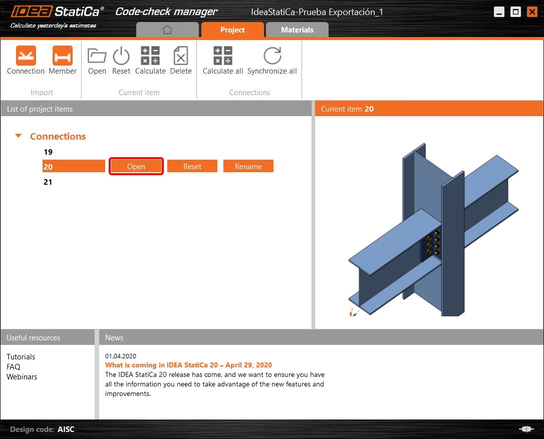
As you can see, the cross-section of the Member 22 has been changed, but all previous operations remained.

You have imported, designed, and code-checked a steel joint according to AISC.
ข้อจำกัดที่ทราบสำหรับ ETABS และ SAP2000
ข้อจำกัดของการเชื่อมโยง BIM สำหรับ Concrete
ต่อไปนี้คือข้อจำกัดและข้อควรพิจารณาในปัจจุบันเมื่อใช้การเชื่อมโยง BIM ของ ETABS/SAP2000 กับ IDEA StatiCa Checkbot และ Detail 2D โดยเน้นข้อจำกัดที่อาจเกิดขึ้น ปัญหาที่พบบ่อย และแนวทางปฏิบัติที่แนะนำเพื่อให้การวิเคราะห์และการออกแบบมีความถูกต้อง
ข้อจำกัด: การนำเข้า
หากกรณีแรงกระทำของ ETABS มีขั้นตอนการวิเคราะห์ IDEA StatiCa Checkbot จะไม่สามารถพิจารณาทั้งหมดได้
- แนะนำให้แยกกรณีแรงกระทำแบบขั้นตอนออกเป็นกรณีแรงกระทำแต่ละกรณีก่อนนำเข้า
ข้อจำกัด: ฟังก์ชันการซิงค์
เมื่อซิงค์โมเดล ประเภทการรวมแรงกระทำจะถูกรีเซ็ต
- ผู้ใช้ต้องกำหนดประเภทการรวมแรงกระทำที่ถูกต้องใหม่หลังจากการซิงค์แต่ละครั้ง
ข้อจำกัด: การสร้างองค์ประกอบ Detail
ข้อจำกัดต่อไปนี้ใช้เมื่อสร้าง Detail ใน Checkbot:
- Detail สามารถสร้างได้เฉพาะสำหรับองค์ประกอบผนังที่อยู่ในระนาบเดียวกันเท่านั้น
- หากองค์ประกอบที่เลือกไม่อยู่ในระนาบเดียวกัน จะเกิดข้อผิดพลาด และต้องเลือกชุดชิ้นส่วนอื่น
ข้อจำกัด: การส่งออก Detail
เมื่อส่งออก Detail ข้อจำกัดต่อไปนี้จะมีผล (จะแสดงคำเตือนใน Checkbot เมื่อเกี่ยวข้อง):
- แรงกระจายนอกระนาบที่กระทำกับชิ้นส่วน 2D จะไม่ถูกถ่ายโอนไปยัง Detail 2D
- ชิ้นส่วน 2D จะไม่ถูกรวมหากมีความหนาต่างกัน วัสดุต่างกัน หรือค่าแรงกระทำในระนาบต่างกัน
- แรงกระทำนอกระนาบไม่สามารถส่งออกได้ จะแสดงคำเตือนหากแรงกระทำรวมที่ขอบสำหรับกรณีแรงกระทำเกิน ±1 kN
- ชิ้นส่วน 2D ที่ไม่ตั้งฉากไม่ควรถ่ายโอนไปยัง Detail 2D; แอปพลิเคชันไม่เหมาะสำหรับชิ้นส่วนดังกล่าว
ปัญหาที่พบบ่อยในขั้นตอนการทำงาน
- แรงกระทำแบบจุดเข้มข้นอาจทำให้การวิเคราะห์แบบไม่เชิงเส้นล้มเหลว เพิ่ม อุปกรณ์ถ่ายแรง (เช่น แผ่นรองรับแรง) เพื่อกระจายแรง
- ตาข่ายของ ETABS หรือ SAP2000 ที่หยาบ (ซึ่งเป็นเรื่องปกติสำหรับโมเดลรวม) อาจทำให้เกิดจุดสูงสุดของความเค้นและสร้างแรงเข้มข้นที่ไม่สมจริงทั้งในด้านค่าและตำแหน่งสำหรับการออกแบบเหล็กเสริม
- คำแนะนำ: ปรับตาข่ายเป็น 100 มม. x 100 มม. สำหรับองค์ประกอบผนังที่นำเข้า
- ตาข่ายที่หยาบยังอาจทำให้เกิดโมเมนต์ในระนาบที่มีนัยสำคัญซึ่งไม่สามารถจับได้อย่างถูกต้องใน IDEA StatiCa
- คำแนะนำ: ตั้งค่าความแข็งนอกระนาบขององค์ประกอบผนังที่นำเข้าให้มีค่าต่ำ เพื่อให้องค์ประกอบโครงสร้างโดยรอบในโมเดลรวมสามารถรับและถ่ายแรงนอกระนาบได้อย่างเหมาะสม
- หากแรงกระทำแบบจุดที่ขอบทำให้เกิดแรงดึงที่ขอบ (เช่น จากแรงด้านข้าง) การวิเคราะห์แบบไม่เชิงเส้นอาจล้มเหลว
- คำแนะนำ: เลื่อนแรงกระทำแบบจุดเข้าด้านในเล็กน้อยเพื่อให้ Concrete ทำงานได้อย่างถูกต้อง

ข้อจำกัดของการเชื่อมโยง BIM สำหรับโครงสร้างเหล็ก
การเชื่อมโยงนี้รองรับการเชื่อมต่อ/จุดต่อที่หลากหลายในปัจจุบัน อย่างไรก็ตาม โปรดคำนึงถึงฟังก์ชันที่ยังไม่รองรับดังต่อไปนี้:
ข้อจำกัด: การนำเข้าแรงกระทำ
ไม่รองรับการนำเข้าการรวมแรงกระทำที่มีการรวมแรงกระทำในลักษณะอื่นนอกจากเชิงเส้น
ไม่รองรับการอ้างอิงการรวมแรงกระทำภายในการรวมแรงกระทำอื่น
ข้อจำกัด: วิธีการรัน SAP2000 และ ETABS ร่วมกับ IDEA StatiCa 22.1
เวอร์ชันที่มีปัญหา:
- SAP2000 24.1.0
- ETABS 20.3.0
คำอธิบายปัญหา:
แพตช์ใหม่ของ SAP2000 24.1.0 ไม่ทำงานร่วมกับ IDEA 22.1 เวอร์ชันล่าสุด เมื่อเริ่ม Checkbot จากเมนู จะปรากฏดังนี้ และไม่สามารถดำเนินการ/คลิกสิ่งใดได้
วิธีแก้ไข:
วิธีนี้ใช้ได้กับทั้ง SAP2000 และ ETABS (เวอร์ชันล่าสุด) วิธีแก้ปัญหาชั่วคราวคือ:
1. ค้นหาไฟล์ config (ไม่ว่าจะเป็น SAP2000.exe.config หรือ ETABS.exe.config) ใน
C:\Program Files\Computers and Structures\SAP2000 24\
หรือ
C:\Program Files\Computers and Structures\ETABS 20\
2. ลบบรรทัดต่อไปนี้จากส่วนท้ายของไฟล์และบันทึก (ต้องใช้สิทธิ์ผู้ดูแลระบบ)

หรือจะคัดลอกไฟล์ไปยังเดสก์ท็อป แก้ไขที่นั่น แล้วคัดลอกกลับไปยังโฟลเดอร์เดิม
นี่คือลักษณะที่ไฟล์ควรจะเป็น (ส่วนท้าย) หลังจากลบ assembly binding อย่างถูกต้องแล้ว:
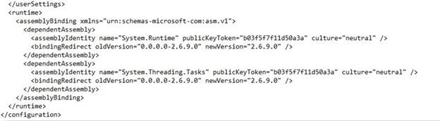
3. จากนั้นจึงสามารถรัน Checkbot ได้
ข้อจำกัด: สมดุล
เพื่อให้แน่ใจว่า Node มีสมดุล โปรดตั้งค่า End Length Offsets เป็น 0:


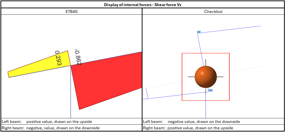
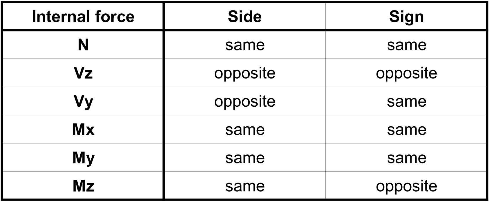
ข้อจำกัด: ข้อตกลงเครื่องหมายสำหรับแรงภายใน
เนื่องจากข้อตกลงเครื่องหมายที่แตกต่างกันระหว่าง ETABS และ Checkbot แรงภายในจึงแสดงผลแตกต่างกัน ผลของแรงกระทำถูกนำไปใช้อย่างถูกต้อง แต่แรงภายในอาจแสดงด้วยเครื่องหมายตรงข้ามและถูกวาดอยู่อีกด้านหนึ่งของคาน
ข้อจำกัด: การติดตั้ง SAP2000 หรือ ETABS หลายเวอร์ชันบนคอมพิวเตอร์
ETABS และ SAP2000 API ใช้ COM library ซึ่งต้องลงทะเบียนใน registry เมื่อติดตั้งเวอร์ชันใหม่ ระหว่างการติดตั้ง COM สำหรับเวอร์ชันนั้นจะถูกลงทะเบียนโดยอัตโนมัติ ดังนั้นเมื่อพยายามรันการเชื่อมโยง Checkbot สำหรับเวอร์ชันเก่า จะไม่สามารถทำงานได้
หากต้องการสลับระหว่างสองเวอร์ชัน ต้องดำเนินการดังนี้:
1) รันในฐานะผู้ดูแลระบบ "UnregisterSAP2000.exe" หรือ "UnregisterETABS.exe" ในโฟลเดอร์ของเวอร์ชันใหม่กว่า
2) จากนั้นรันในฐานะผู้ดูแลระบบ "RegisterSAP2000.exe" หรือ "RegisterETABS.exe" ในโฟลเดอร์ของเวอร์ชันเก่ากว่า