Steel Connection Design
Parametric templates in Connection Library
In IDEA StatiCa Connection, we have the possibility to create connection models using parameters (relations defined between individual entities). The parametric design allows us to design standardized connections efficiently – read about how to work with parameters in this article.
The integration of parametric templates into the Connection Library offers a transformational approach to connection designer workflows. It allows users to create and use a universal collection of templates that can be effortlessly customized and deployed in different design contexts.
How does it work?
The user can upload the created connection to their company or personal set as with any design, and it can even be done with the defined parameters. Once there is the same geometry in the project and the solution can be repeated, the user can apply this pre-prepared design (template) with all the parameters.
In addition, after proposing the template, it is possible to change the parameters directly in the main design window, and there is no need to go into developer mode. This user-friendly environment allows less-experienced users to work with predefined parameters safely according to the presets of the senior designers.
This makes further optimization very simple as there is the possibility of avoiding changing each entity one by one when using operations.
By changing one parameter, multiple steps can be performed at once. For example, when changing the widener width, not only the widener itself, but also all the related welds and the location of the stiffener are affected:
The locked modifications in the property list of some manufacturing operations are disabled in such cases. However, if the user wishes, they can break the parameters using the "explode" button, and continue with modifying operations.
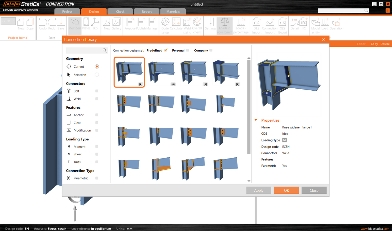
The templates to which the parameters are linked are marked with a lowercase {p}. Several parametric templates have already been prepared and made available in the predefined design set by the IDEA StatiCa team.
What are the benefits of parametric templates?
- Universal templates: Designers can access a broad collection of parametric templates from the Connection Library. These templates are designed to be universally applicable, providing a solid foundation for a wide range of projects.
- Parametric customization: Through the Developer tab, users can define specific parameters for each template, allowing for a high degree of customization and flexibility in design.
- Template identification: Parametric templates are easily identifiable by the symbol {p}, ensuring that users can quickly recognize and select them for their projects.
- Enhanced library filtering: The filter in the Propose window of the Connection Library, enables users to efficiently find parametric templates among the library's extensive offerings.
- Publication control: When a connection contains parameters, designers have the option to publish these parametric templates to the Connection Library. This feature offers flexibility in sharing customized templates with the broader user community or keeping them private for individual or internal use.
Impact on workflow
The inclusion of parametric templates in the Connection Library represents a significant advancement in the design process for connection designers. This functionality simplifies the design process by providing:
- Efficiency: The use of templates speeds up the design phase, allowing for quicker iterations and modifications.
- Consistency: Parametric templates ensure design consistency across projects, which is crucial for maintaining standards and quality.
- Collaboration: The ability to share customized templates enhances collaboration among teams and with the wider design community.
- Customization: Designers can tailor templates to specific project requirements, enhancing design accuracy and effectiveness.
Released in IDEA StatiCa patch 23.1.5.
Default control sets in the Operations (in version 24.1)
The design of connection by parameters consists of the setting of very unique parameters specific for every single connection type on one hand. On the other hand, there are parameters that are used almost always due to common engineering practices, such as a set of welds, fasteners, and materials.
To simplify the creation of parametric templates and to reach this setting anytime, we include these controls as default sets in the operation root.
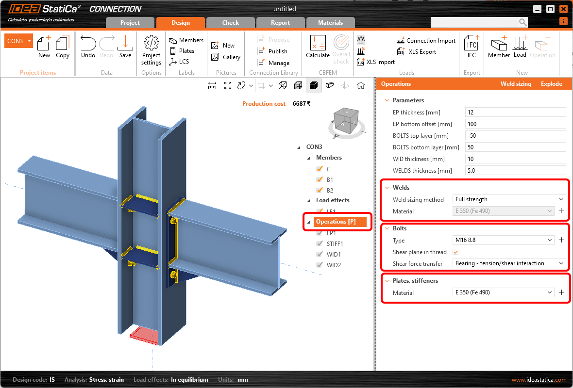
When you select the Operations, there are, by default, the following settings:
- Weld setting: Weld sizing method and weld Material (24.0.5)
- Bolt setting: Type, Shear plane in thread, and Shear force transfer (24.1.0)
- Plates setting: Material (24.1.0)
These controls set the specific property for the whole connection model to all operations and are shown in Operations root by default. They do not change the properties of the structural members, only the manufacturing operations.
In case any of the properties related to the control is used in any parameter of the parametric template, the control is automatically disabled. By this behavior, we prevent the possibility of influencing the same property from two places and, thus, ruining the connection detail by loops in parameters.
As a benefit, these controls are also shown without a parametric template, enabling quick changes and unifying properties of any connection model.
What are the benefits?
- For the parametric template user (e.g., junior user), all operations are disabled (read-only). However, changing the material, bolt class, or plate material is still a commonly expected action. However, if there was a single parameter missing in the parametric template, it made the template unusable. Common properties such as welds, bolts, and material can now be controlled in each parametric template using the default controls shown under the parameters.
- Adding these controls simplifies the work of the template creator (e.g., senior user) in preparing the parametric templates. Now, it is not necessary to manually create special parameters for modifying common properties such as welds, bolts, and materials.
- Sometimes, you want to unify bolt grades or plates and weld material in the whole connection detail even when the parametric template is not used. It can be easily either done by multi-selecting in the tree and editing operations of the same type (nevertheless, in this case, it has to be done multiple times for each group of operations separately), or it is now possible to change the requested property or just check if the same property is used in one click.
Download the latest version of IDEA StatiCa and try all the features
Enhanced sketches in reports
2D drawings, named user-defined sections in the Connection app, are one of the most common ways to provide details of connection design.
Therefore, after refining the data contained in the sketches and avoiding overlapping of the annotations, you can achieve optimized readability. That means that every detailer is able to easily and clearly read the required data from the sketches.
The results in enhancement to the Section model view – drawings (“sketches”).
Better readability of sketches
The sketches' readability is critical for avoiding mistakes in the final design in 3D CAD software due to the needs to avoid overlapping texts with the lines, etc. By providing clearer sketches where the annotation marks do not overlap with other objects anymore, the sketches are simple, clear, and fully readable.
No overlapping of texts and lines
The special allocation algorithm eliminates the aforementioned overlapping of annotation marks in sketches, preventing the occurrence of cluttered sketches.
To enhance sketch readability and annotation distribution, we use a quadrant principle: By centering the picture and dividing sketches into four quadrants around the node base point, annotations are strategically placed in the best positions within the corresponding quadrant. Using this principle, we reach a much better and more logical distribution of the annotation marks of plates, welds, and bolts.
Big display in the report
Sketches occupy approximately two-thirds of an A4 page, ensuring readability and utility in the final report. This prevents sketches from being too small and surrounded by excessive empty spaces, detracting from the overall quality and effectiveness of the documentation.
Sketches are set to ON in the report by default.
Improved annotations of operations
Annotations in key manufacturing operations such as fin plate, widener, stiffener, and gusset plate, help streamline the design process and eliminate sketch overlaps. Repositioning annotations, adding missing dimensions, and correcting inaccuracies avoid the risk of unclear sketches and incomplete details.
Section Editor and settings
The Section Editor accelerates the management and customization of user-defined sections within the Design tab, directly affecting ease of use. These settings are reflected in the Report and preserved with the model, ensuring consistency across documentation. You have the flexibility to easily remove sections or tailor the visibility of various annotations to suit the complexity of the section, resulting in clarity and user control over section presentations.
It is available in the Design tab, directly under the original button for opening the section mode view.
Functions available in the section editor are:
- Show/hide annotations
- Show/hide member and plate labels
- Show/hide bolt descriptions
- Show/hide weld symbols
- Delete sketch
How to work with sketches
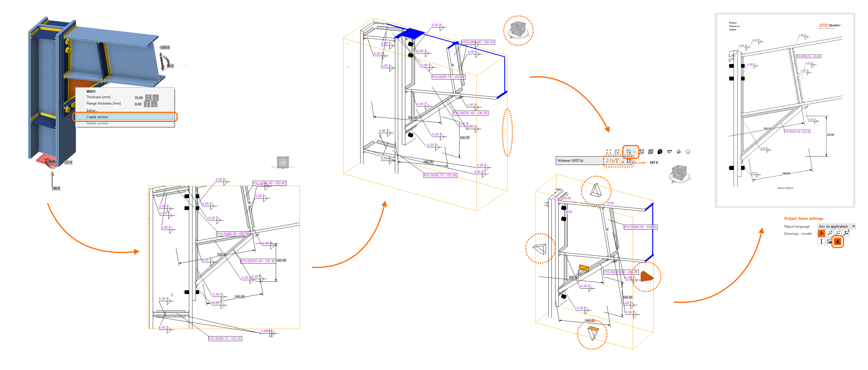
- To create a new sketch/section view, use the right mouse button in the 3D scene and select Create section.
- Rotate the model to view the orange box defining the section.
- Click its boundaries and adjust them using the arrows around the box.
- In the menu above the 3D scene, you can select which entities will be included in the section view.
- The sketch will be automatically printed in the report unless you change the settings.
You can edit the section anytime using the Section editor button in the menu above the 3D scene. Also, you can create as many sections as you wish.
Find out more in the How to create a section view article.
Released in IDEA StatiCa version 24.0.
Take the latest IDEA StatiCa for a test drive today
Automatic weld sizing to ductility
The aim of this feature is to control the ductility level in all welds in the connection with one click! This weld sizing approach uses an algorithm that adjusts the weld size according to the strength of connected plates (parent metal). In the IDEA StatiCa Connection application, there are three levels of weld sizing per ductility:
- Weld sizing to minimum ductility (Eurocode only)
- Weld sizing to full-strength
- Weld sizing with overstrength
The algorithm for each level of ductility is governed by the following equations.
Weld sizing to minimum ductility
This method modifies weld size to minimum ductility of welded joints as per the Eurocode requirements in FprEN 1993-1-8:2023 – 6.9(4), and it applies to all welds and all different steel grades used in the model. The weld resistance is designed to be high enough to prevent brittle failures in the connection and, at the same time, allow plastification in the connected weld.
Minimum ductility requirements are also included in the detailing check of welds.
Note: Weld sizing to minimum ductility is available for Eurocode (EN) only.
Weld sizing to full-strength
The full-strength weld sizing algorithm produces thicker welds than the minimum ductility type. The resistance of the weld is higher than the resistance of the plate connected by edge. This means, welds designed with this criteria will not brittle fail before the plate fails.
Weld sizing with overstrength
This type of weld sizing produces even thicker welds than the full-strength, so the welds are much stronger than the connected plate. The aim is to add more safety in the plastic design approach and for cyclic loading scenarios (e.g., some seismic loads). The algorithm here is the same as for the full-strength, but the weld size is multiplied by the Overstrength factor.
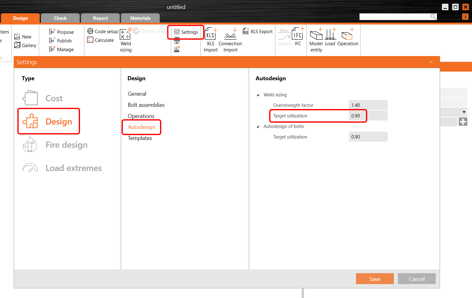
By default, the Overstrength factor is set to 1.4 and can be changed in the project Settings/Design/Autodesign/Overstrength factor.
Executing the weld sizing to ductility levels
To run the automatic weld sizing, right-click the Operations item in the tree menu and carry out the weld sizing from here by choosing the weld sizing method.
Alternatively, you can click the Operations in the tree menu, select the desired Weld sizing method, and run the Weld sizing command in the ribbon.
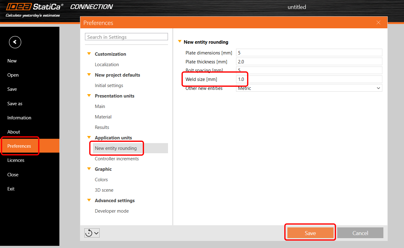
Welds size rounding up can be defined in application Preferences/New entity rounding/Weld size.
Read more about the weld sizing method in the Theoretical background chapter.
Released in IDEA StatiCa version 24.0.
Take the latest IDEA StatiCa for a test drive today
Automatic weld sizing to capacity estimation
Simply put, weld sizing to capacity estimation enables you to, with one click, optimize the size of each weld across the whole connection model with a preset utilization level! Such easiness in user execution makes this feature the most advanced weld optimization tool on the market.
Machine learning technology
This feature for Eurocode (EN) projects performs the capacity estimation of all welds in the model, leveraging the machine learning data containing thousands of weld models with various loading scenarios. The capacity estimation routine considers both connection design and the load effects.
First, the Connection model is calculated with the original welds, and then these results are compared to the vast library of machine-learned results database, and weld sizes are optimized.
More about capacity estimation weld sizing in the article Welds – autodesign, input, warnings, visualization.
How to perform the capacity estimation weld sizing
To execute the automatic weld sizing, click the Operations in the tree menu, select To capacity estimation weld sizing method, and run the Weld sizing command in the ribbon.
Alternatively, you can right-click the Operations item in the tree menu and carry out the weld sizing from here. For To capacity estimation, you must first run the standard Calculation.
Utilization level and precision settings
Welds are automatically adjusted based on utilization using this method to calculate the optimized throat thickness:
Throat thicknessopt = Throat thickness * Utc / Target utilization
The utilization value is displayed in Check under the Welds tab in the Utc column. More about Utc and welds in this article.
Welds utilization level can be controlled in the project Settings/Design/Autodesign/Target utilization.
Welds size rounding up can be defined in the application Preferences/New entity rounding/Weld size.
Detailing requirements are taken into account regarding the weld sizing.
Read more about weld sizing in the Theoretical background.
Note: Weld sizing to capacity estimation is available for Eurocode (EN) only.
Released in IDEA StatiCa version 24.0.
Take the latest IDEA StatiCa for a test drive today
Partial Joint Penetration (PJP) groove welds
IDEA StatiCa Connection offers PJP groove welds as an option for welds as per AISC 360 standards (2010, 2016, 2022 in table J2.5). Users can specify any weld that is edge-to-surface as a PJP weld in every manufacturing operation, e.g., weld or contact, fin plate, etc.
The checks are affected if the Base metal capacity at the fusion face is turned on in the Code setup. The Directional strength increase is not accounted for when using PJP welds.
For better reporting, special symbols for PJP welds and detailed formulas are provided, along with an adjusted analysis model that reflects accurate load-deformation curves and plastic stress redistribution.
In user-defined sections, a butt weld symbol with the correct effective throat thickness is displayed so that the produced drawings for reports are fully reliable.
The edge-to-rod type of PJP welding is not available and is converted to a full-penetration butt weld, which is not checked and is considered a part of the parent metal plate. Read about how to use rod member connections.
The ability to define PJP welds broadens the scope of design possibilities, allowing for more accurate and code-compliant projects.
Note: The Partial Joint Penetration (PJP) groove welds are available for AISC code only
Released in IDEA StatiCa version 24.0.
Take the latest IDEA StatiCa for a test drive today
Steel pins
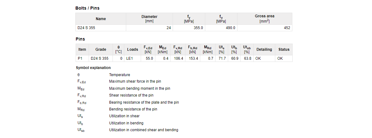
Pins can be used for modeling pin connections as well as help in cases where a one-bolt connection doesn't meet the requirement in EN 1993-1-8, 3.13.1 (2) and has to be checked as a beam element with bending - pin.
How to model a pin
There is a Pin type of fastener within the operation Fastener grid and Contact. When Pin is selected, the count of items is automatically changed to three, which is the minimum number of connected plates.
The pin can also be designed as Replaceable, which governs the used checks according to code.
A member connected by a pin must have the model type N-Vy-Vz specified, otherwise, the analysis leads to a singularity.
The contact between plates is created automatically if the distance between connected parallel plates is less than 2 mm. If the gap is bigger than 2 mm, the contact is not created.
Pins in the project material database
The geometric parameters of a pin (pin diameter, material, hole size, pin head...) can be defined in the Materials tab similarly to bolt assemblies. The diameter of a pin can be selected from the predefined material library.
Structural steel material (e.g., S355) is used as the default material for pins. In case a steel bolt material (e.g., 8.8) or any other type of material needs to be defined for pins, it can be done by editing the properties of added structural steel material (fu, etc.).
A Pin cap can be turned on, but it doesn't influence the checks or analysis, only the visual presentation of pins in the 3D scene.
Code checks of pinned connections
Checks are provided according to EN 1993-1-8, 3.13.2.
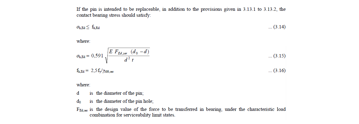
If the pin is set as replaceable, different checks are used according to Table 3.10 and Equation 3.14.
When the fire resistance analysis type is performed, the replaceable setting of used pins is ignored, and all pins in the model are checked as non-replaceable.
Pins in results and report
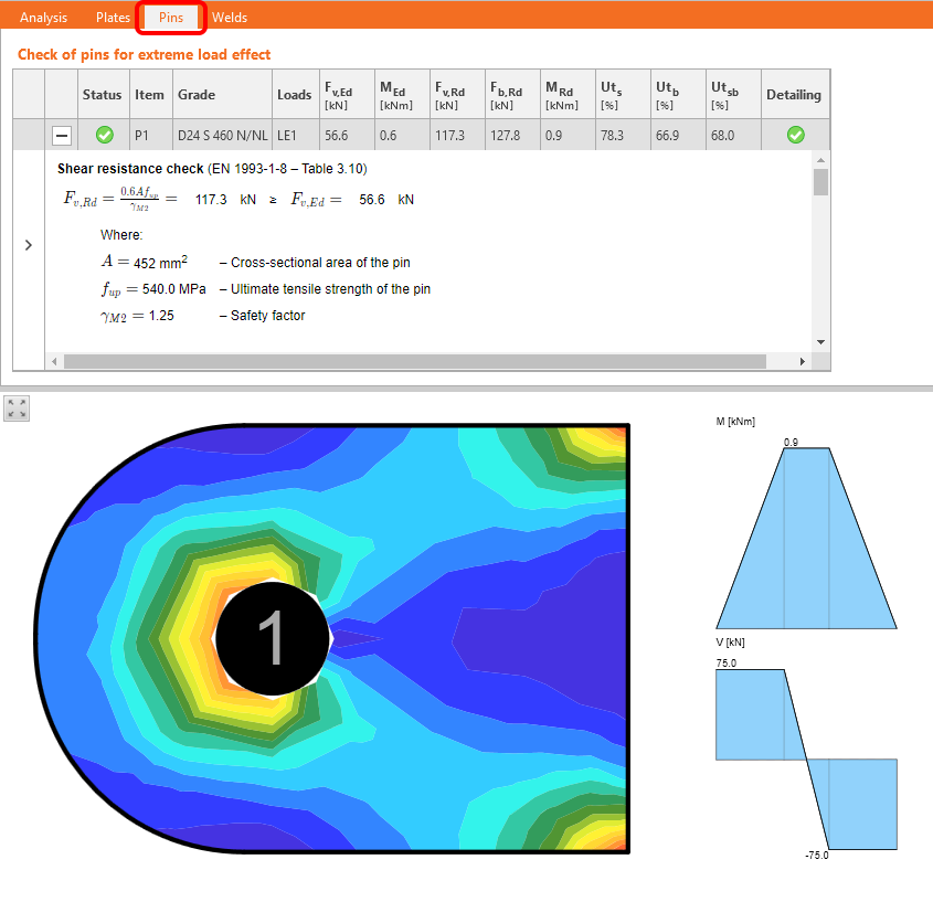
There is a check tab for pins with detailed results and code equations listed in the Check tab. Also, the bending moment diagram for the pin is displayed along with the stress/strain in the connected plate.
All relevant input data and result data of pins are included in the report.
Detailing checks for pinned connections
Basic detailing checks are provided according to Table 3.9 - type A. For finding the edge distances "a" and "c", identical logic is used as the one used for determining the edge distances of bolts (dependent on vector direction).
CBFEM analytical model of a pin
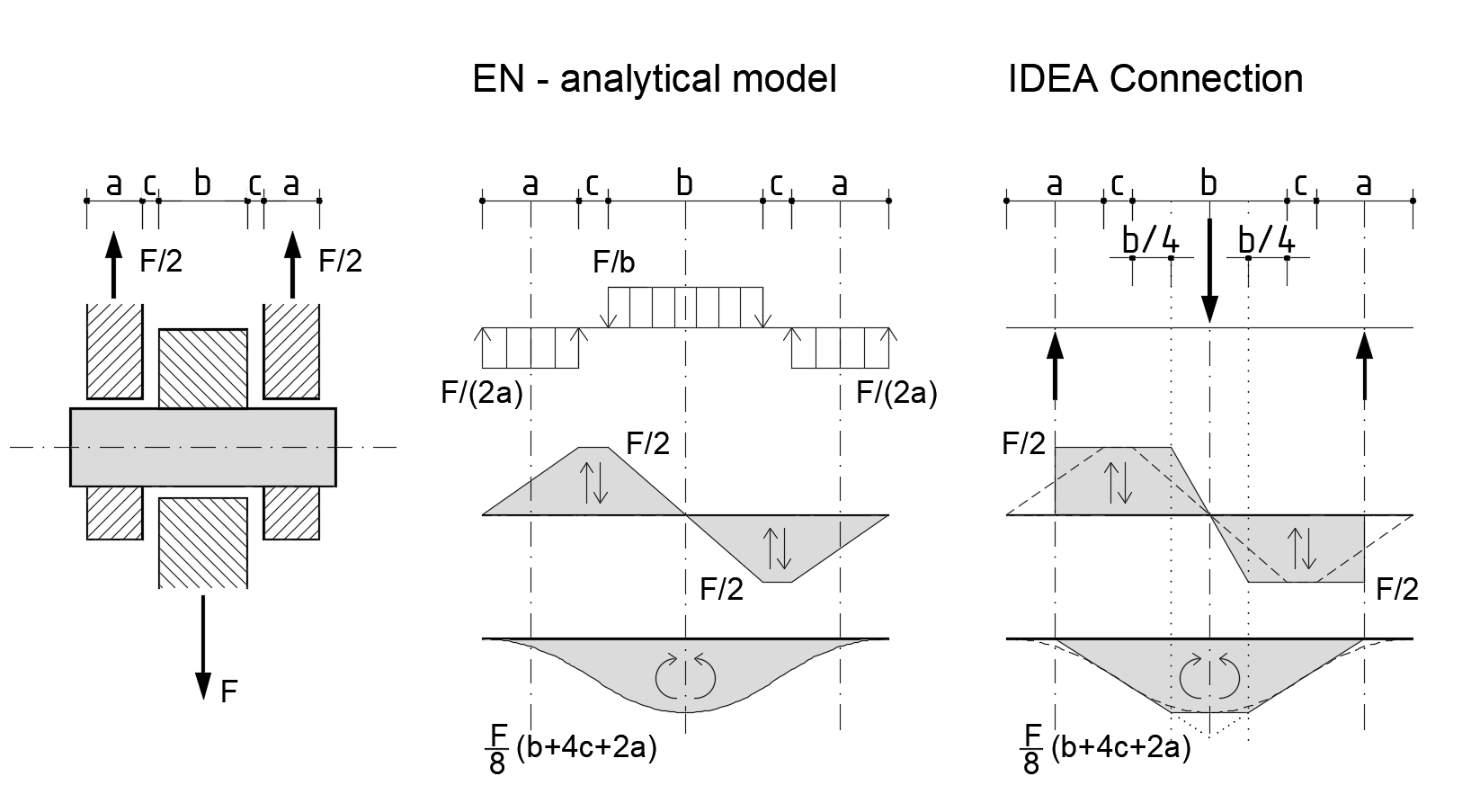
Pins in CBFEM are modeled as linear elastic beam elements. The pin model is implemented in such a way that individual plates are not connected in the direction of the pin axis, and, thus, no normal force is generated in it. Only shear force and bending moment are active.
In the Connection app, the forces are applied to the pin as point loads in the axis of connected plates, and the bending moment diagram in a pin has a simplified linear shape compared to the analytical model in the Eurocode. Internal forces in the pin are evaluated and presented in a quarter of the inner plate thickness, which ensures that shear force and bending moment maximum values used for the code-checks are identical to extreme values from the analytical Eurocode model.
Note: Pins are available for Eurocode (EN) only.
Released in IDEA StatiCa version 24.0.
Take the latest IDEA StatiCa for a test drive today
Hooked anchors/L-bolts in AISC
In the design and check of footings, an AISC project can consider a hook type of anchor for the foundation concrete block.
The L-shaped anchors can be defined either in the base plate or in the fastener grid or contact operations.
The hook length must be at least three times the anchor diameter, as per ACI 318-19 - 17.6.3.2.2. A warning appears when this condition is not met.
You can find the concrete pullout resistance check as per ACI in the report. For more information about the checking of anchors and a concrete block according to AISC, go to Check of steel connection components (AISC).
Released in IDEA StatiCa version 24.0.
Take the latest IDEA StatiCa for a test drive today
Check of anchor tension as a bolt tension option (AS)
In projects under the AS standard, for the anchor tensile resistance check, you can choose to follow the following (in the Code Setup):
- AS 5216:2018 – 6.2.2 (default)
- AS 4100:2020 – 9.2.2.2
If the AS 4100:2020 – 9.2.2.2 (as it is used for bolts) is selected, the anchor tensile resistance is replaced by the bolt check as follows:
Anchor tensile resistance (AS 4100:2020 – 9.2.2.2)
Released in IDEA StatiCa version 24.0.
Take the latest IDEA StatiCa for a test drive today
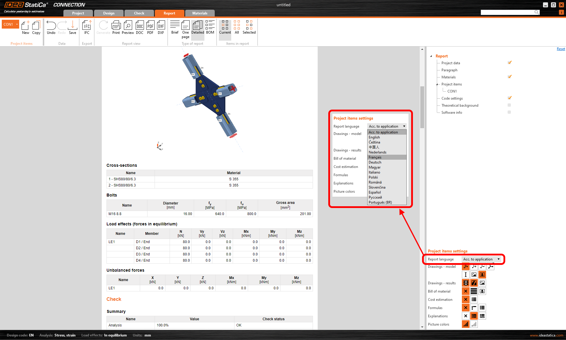
Change just the language of the report
Sometimes, the project report should be submitted in a language that you do not speak. In some software, that means changing the language of the whole application (and restarting it) just to print the reports.
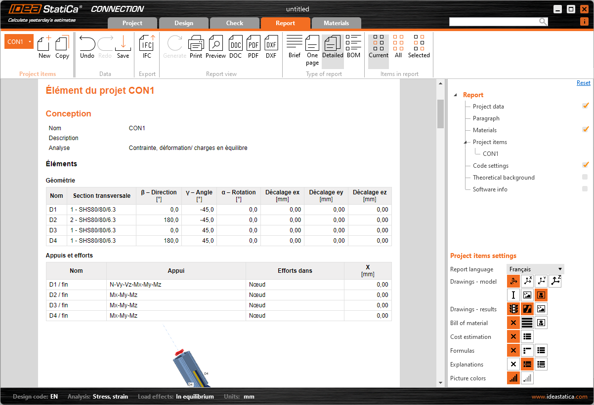
The possibility of changing the report language under the Report tab makes this tedious process unnecessary.
After re-generating the report, the document can be saved/printed in the changed language while the application interface stays unchanged.
Available in IDEA StatiCa Connection and Member apps.
Released in IDEA StatiCa version 24.0.
Take the latest IDEA StatiCa for a test drive today
Sliding option for a concrete foundation block
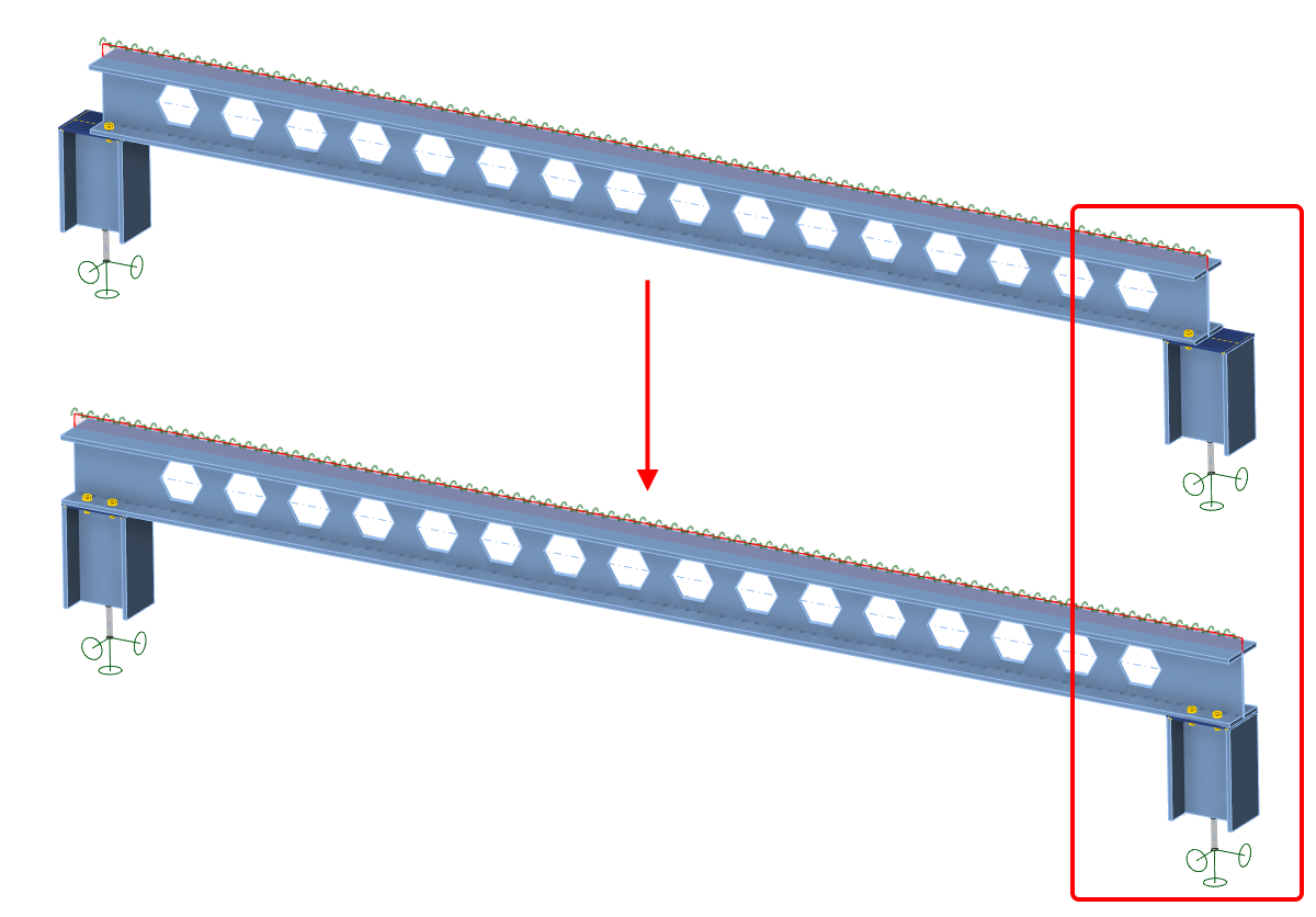
When modeling a simply supported beam in IDEA StatiCa Member, you can use this option for defining the roller (sliding hinge). This option keeps the "close-to-zero" bending moment at the ends of the beam supported by a concrete block.
From Member, open the connection at one end of the beam. Define the anchoring/foundation concrete block and switch the Shear force transfer option to Sliding. Also, remove all the anchors in the Editor.
Please note that the other side of the beam must stay active to transfer forces in both directions so that the static system remains determined.
Although this setting also works in Connection, it is specifically designed to be used in IDEA StatiCa Member.
This feature was released in the IDEA StatiCa 23.1.1 patch.
Take the latest IDEA StatiCa for a test drive today
Execute plate cuts in parallel planes
The Cut of plate operation offers the possibility to cut plates by other plates and negative volumes defined within the same plane. This is beneficial for handling general plate shapes imported from DXF files, addressing the plate cuts that could not be performed in the plate Editor.
To use this feature, select the PCUT (Cut of plate) operation and choose the Surface cutting method within the parameters of picked plates or negative volumes.
See more about modeling in IDEA StatiCa Connection in the recorded webinar Get the most out of Connection modeling.
Released in IDEA StatiCa patch 23.1.1.
Take the latest IDEA StatiCa for a test drive today
Manual control over the extension of members
This setting for "Extend the member" is incorporated in the Connection application inside the Cut of member manufacturing operation. To extend the member towards the farther point of the connected member, you also need to select the Cutting plane type "Farther".
No matter whether the Connection is opened from Member, Checkbot, or initiated from scratch, this functionality uniformly ensures a consistent experience across different workflows.
In the Member application, this feature allows users to extend members at both ends, particularly when an analyzed beam was also cut by another operation, permitting numerous design scenarios.
This unified approach to the extend function in the cut operation between the Connection and Member applications also prevents potential discrepancies.
Released in IDEA StatiCa version 24.0.
Take the latest IDEA StatiCa for a test drive today
Template application dialogue with sketches and parameters
We have introduced the enhanced sketches or, in other words, simple drawings of connections that can be added and printed in the final report. Any defined sketch (user-defined section) can a part of design template published in the Connection Library.
When such a design template is applied to a new connection model, the redesigned conversion dialogue pops up enabling users to:
- See the design standard of the template and the design standard of the current project
- See an overview of members, which one is bearing (underscored), and the mapping between them
- Control mapping of stiffening members
- Each operation has its own row
- Each operation can have an assigned new CSS which will be added to the project
- Control mapping of materials (welds, steel, concrete ...)
- Control the bolt assemblies mapping
- Control pins mapping
- Together with the template the parameters and parametric properties are copied
- Together with the template the sketches are produced
Released in IDEA StatiCa version 24.0.
Take the latest IDEA StatiCa for a test drive today
Consistency in Connection and Member models
The mapping of constraint points and the selection of plates in Cleat, Splice, Fin plate, and Stiffening plate manufacturing operations are consistent in the project data of all applications dealing with steel connections.
This prevents situations when in the Member app, a cut operation (utilizing cut by a plate, workplane of negative volume) is applied in one connection node of the analyzed member, causing discrepancies in the operations in other connection nodes of this member.
A parent-child relationship between plates and members is ensured even after one part of the Member model is touched by modifying the number of edges of plates and their ordering. This methodology ensures that even if the parent plate is removed, the subsequent operations can accurately reference the correct plate based on this relationship, maintaining the intended positioning designed in the Connection application.
Released in IDEA StatiCa version 24.0.
Take the latest IDEA StatiCa for a test drive today
Limiting short lines in DXF imports
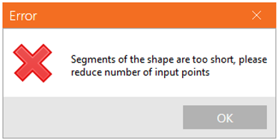
Limiting short lines in DXF imports prevents issues during mesh generation and avoids any interruptions in analysis caused by excessively short lines. The minimum distance between two points is checked against a set limit, which is defined as 1/50 of the bounding box of the cross-section.
Should the distance between any two points fall below this threshold, the user is promptly notified that the points are too close to each other, and the import of the geometry from the DXF file is halted. This measure necessitates users to adjust the geometry in the DXF file to meet the specified conditions before proceeding.
This addresses the challenge where analyses could be disrupted or the application might encounter crashes due to the presence of too short edges in the cross-section definition, leaving users uncertain of the problem's origin. Clearly informing users of non-compliant geometry at the moment of import enables the quick identification and correction of the issue, facilitating a smoother analysis process.
You can read more about creating your own build-up cross-section in How to create and use a custom cross-section and about importing a general plate from a DXF in How to import a plate from DXF.
Released in IDEA StatiCa patch 23.1.2.
Take the latest IDEA StatiCa for a test drive today
High-strength steel notifications
While high-strength steel is not widely covered in the current edition of the Eurocode, it is included in new generations and product sheets. IDEA StatiCa's database accommodates high-strength steel, aligning with current design rules and anticipating future updates to codes and standards.
Enhanced safety and reliability
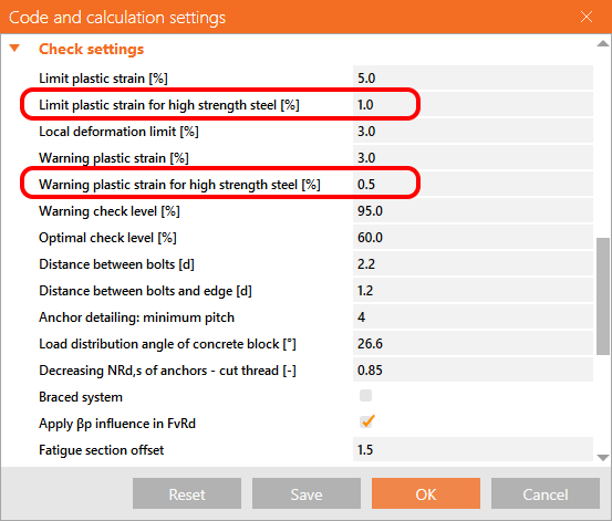
To recognize the unique characteristics of high-strength steel, a distinct plastic strain limit parameter is included in the Code setup, ensuring designs adhere to the most current research and standards.
The inclusion of a separate plastic strain limit for high-strength steel, with a default value set at 1%, allows for precise adherence to material-specific design principles. By specifying a more conservative plastic strain limit for high-strength steel, IDEA StatiCa contributes to the safety and durability of structures.
Design tab and material classification adjustments
For steel with yield strengths fy exceeding 460 MPa, the software alerts the user of a tailored plastic strain limit, ensuring the integrity of designs involving high-strength steel. The automatic update from "Steel" to "High-strength steel" in the software’s database underscores the importance of accurate material properties in design calculations.
The Check tab and Report sections reflect the plastic strain limit ɛlim as per various international codes, including EN, AISC, CSA, AS, and SP, providing a broad compatibility spectrum for global design practices.
Released in IDEA StatiCa version 24.0.
Take the latest IDEA StatiCa for a test drive today
Out of surface load warning in Member
When applying a surface load on one of the member's plates, it may happen that part of the load already lies outside of the plate's surface. In such a case, the full magnitude of the load would not be applied – part of the load would not be transferred and used in the calculation. This might be unsafe and unintuitive, that's why there is a warning message.
When a line or point load distribution area is larger than the plate assigned, a warning is displayed in the top left corner of the screen, and you should adjust the position or the area of action of the load.
This warning helps you overcome these situations and, therefore, improves the safety of the model.
Released in the IDEA StatiCa 23.1.1 patch.
Take the latest IDEA StatiCa for a test drive today
Autodesign of bolts in shear
Autodesign of bolts in shear is another tool that helps speed up the design process and make it more straightforward and automated while keeping safety and cost efficiency. Next to Automatic weld sizing to ductility and Automatic weld sizing to capacity estimation, the feature is the next step in the automated process of connection design.
It brings the simplification of the iteration process of finding the proper design of connections. The autodesign of bolts in shear takes into account the acting loads on simple connections. Instead of an iteration process, the user just calls this autodesign function, and the application finds the proper design.
How to call the function
The function Autodesign of bolts is prepared for two operation types with bolts: Fin plate and Splice.
Once your bolted connection has been calculated, you can call the autodesign from the context menu of the operations – right-click the operation in the tree.
The new design is created based on the selected settings.
What will happen
The function will influence the following parameters:
- Number of bolts
- The geometry of the bolt grid
- Geometry of the plate (plate of fin plate or splice) according to the new bolt grid
- The thickness of the plate (only partly) – to achieve the same bearing resistance as the connected plate (e.g., the web of the beam)
While keeping the following unchanged:
- Diameter and grade of bolts
- The material grade of the plates
Settings
The process is influenced by the Settings. The following values will govern the autodesign process:
- The algorithm checks the Geometry requirements acc. to the Settings: End and edge distance, spacing, and Wall distance and finds the solution to comply with these requirements.
- The algorithm checks the Geometry requirements according to the Preferences: New entity roundings and finds the solution to comply with these requirements.
- The algorithm checks the Target utilization with the real acting loads acc. to the value set in the settings and finds the solution to comply with this requirement. The checked value is Utilization in shear (Uts).
Basic assumptions
- The autodesign algorithm takes into consideration only forces and moments in the plane of the plate (N, Vz, My - generating only shear forces for the bolts) from the acting load effects in the model. Any tension forces occurring in the bolts (generated by other loads or prying) are not taken into consideration in the autodesign process.
- If the tension utilization is high, autodesign could give inprecise results, and the user may receive a warning message. The autodesign is provided, but the results can be significantly influenced by tensile force in the bolts.
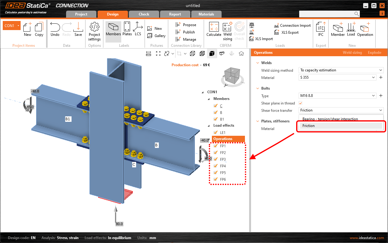
- Bolts in the operations have to be set with the bearing/shear interaction shear force type. Autodesign is not performed if bolts are set as friction and the user receives a warning message.
- The forces in bolts are not calculated correctly when the model is overloaded, and the analysis is finished with a huge plastic deformation. Therefore, the autodesign is working with incorrect forces in the bolts and can not give any correct result.
- The feature is available for the common cross-section types only, not all cross-sections are supported.
- If the selected cross-section is not suitable for placing the bolt grid according to geometrical requirements, you may also get a warning. For example, in cases with narrow flanges, it is impossible to comply with requirements for edge distances, distances from the wall, etc.
Take the latest IDEA StatiCa for a test drive today
Concrete Design
3D Detail – reinforced concrete footings (BETA)
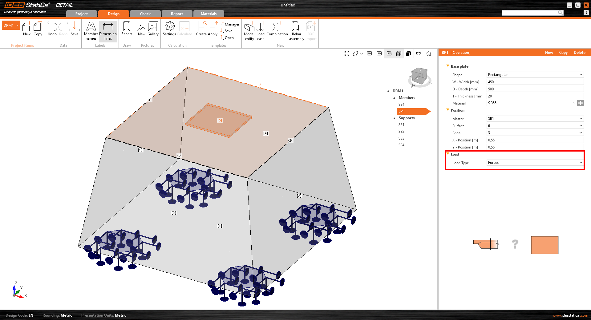
IDEA StatiCa introduces Detail (3D Beta) for solving 3D tasks such as anchoring in concrete blocks. The solution lets you perform the design without oversimplification and obtain checks based on the Ultimate Limit State (ULS). The method implemented in IDEA Statica Detail (3D Beta) is based on the already proven Compatible Stress Field Method, which was adjusted to be able to solve 3D problems (tri-axial stress). Also, the basic element is modified to the third dimension. The solid block is the basic element representing concrete and can be deformed in all three directions. To make it possible to create a complex model for footings, we have implemented entities such as surface support, base plate, anchors, and more. All these entities are described, as well as their functionality, in the following article.
The shape of the solid block
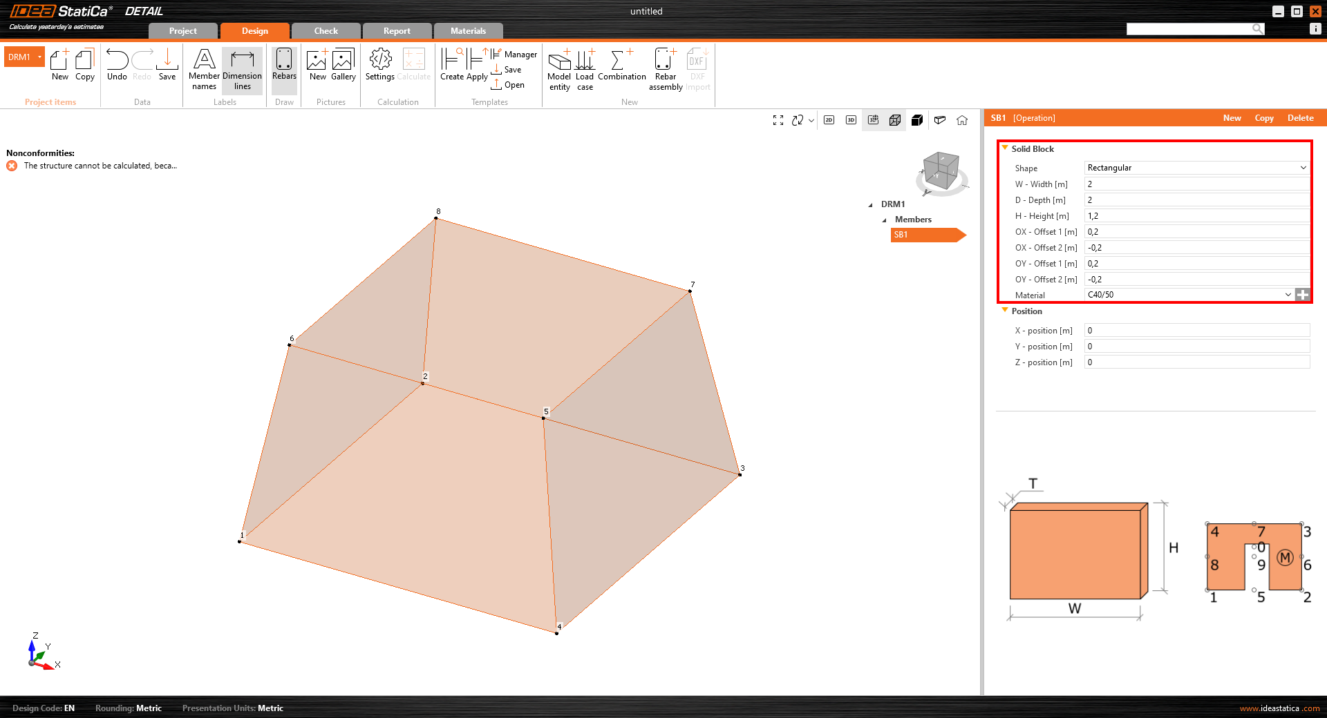
Concrete block can be modeled thanks to the member type called "Solid block", whose geometry can be defined in two ways:
- Rectangular shape – This option is suitable for defining the footing with a rectangular base and constant height. Defining offsets for all sides of the block also allows sloped footing to be modeled.
- Polygonal base with a defined height – The second option for defining a footing shape is the definition of the base shape as a general polygon. However, it is not possible to create sloped footing as described in the previous option.
Surface supports
Surface support is the only possible support type that can be defined for the solid model. There are two options for the shape definition – it can be defined either for the whole surface or as a general area whose outline is determined by polyline.
The advantage of surface support is the possibility of defining stiffness and setting non-linear behavior that simulates contact with the soil. Supports defined by general shape (polyline) can be used to simulate piles.
Load transfer devices
Especially for the anchoring, two entities to transfer loads were developed:
- Base Plate – The shape of the base plate can be defined as a rectangle or a general polyline. The base plate can be modeled with the part of the column (option “Load transfer – Column”) or without the column (option “Load transfer – Forces”). When option “Load transfer – Forces” is selected, the defined load is applied directly to the base plate. When the steel column is defined (by its cross-section and length), the load is applied to the top of the column, and its stiffness helps distribute the stress correctly to the base plate.
- Single Anchor – A single anchor is a 1D element allowing the transfer of axial load. The anchor can be automatically interconnected with the base plate or it can be loaded directly by the point load*.
*There are several limitations for anchors in BETA.
The anchor transmits only compression and tension. Shear, if imported from Connection, is transferred by friction between the concrete block and the base plate. Only axial force can be applied to the anchor.
There are two different types of anchors available in the Detail app:
- Cast-in place – Reinforcement
- Adhesive anchor
For Adhesive anchor, there is another parameter coming into the analysis – Bond strength. This value is set by default to 2 MPa and should be adjusted by the user according to the datasheet info from the anchor manufacturer.
Loads
Adding a group of forces and surface load is essential for ease of use. In total, we support three load types:
- Surface load – Surface load can be applied to any concrete surface. It can be applied to the whole surface or just on its part over a certain area, which is determined by its outline (polyline).
- Point load
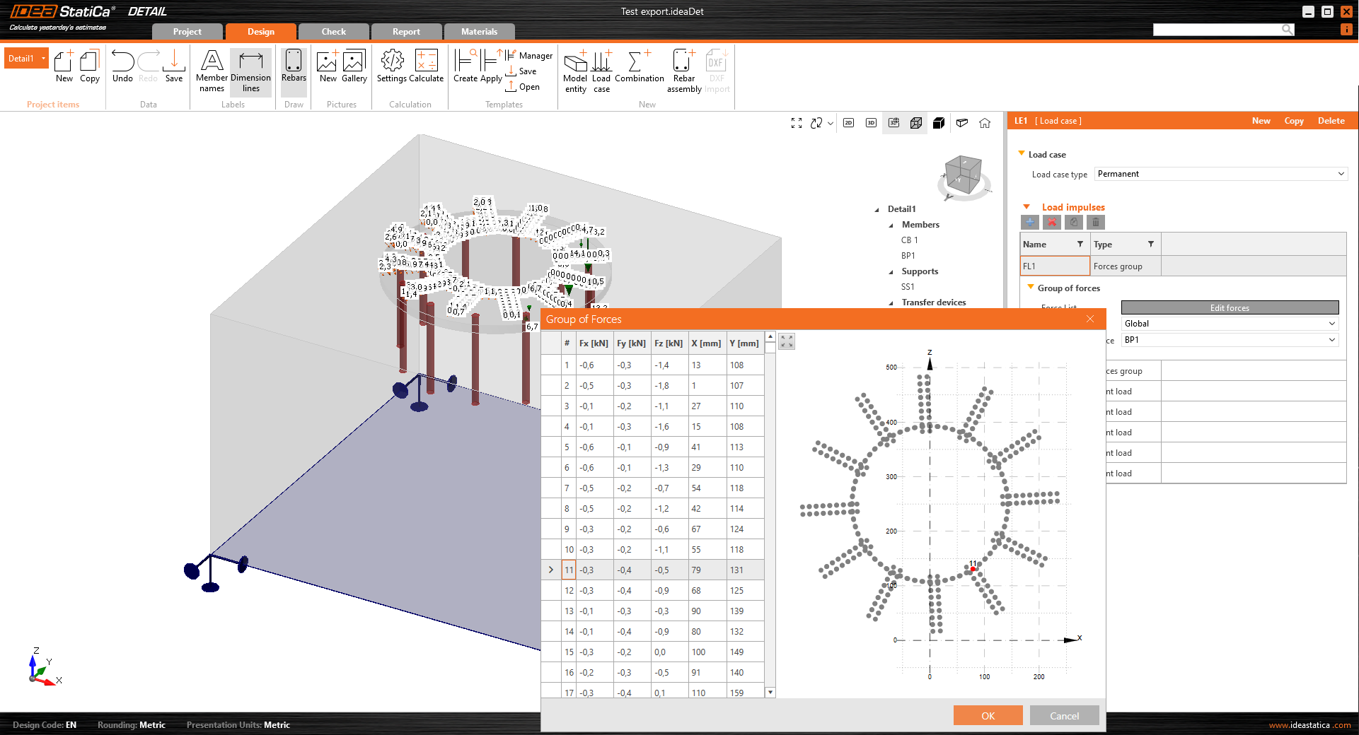
- Group of forces – A group of forces is an entity that defines several point loads acting as a group. It can be applied on the base plate or the concrete surface. This load type can be used to simulate forces in welds transferring stresses from the column to the base plate.
Reinforcement
A new type of reinforcement was developed, allowing the reinforcement of a footing to be sufficiently reinforced. A Group of bars provides several options for the definition of the rebars:
- By two points
- On surface edge – On surface edge – a reinforcement layer is created parallel to the selected surface. The user defines several bars in a layer and a number of layers parallel to the selected surface.
- On surface edge or more edges – On surface edge or more edges allow the modeling of layers of rebar with a complex shape (plane curve related to any concrete surface). The layer is, therefore, determined just by one rebar. However, several parallel layers can be defined. Concrete cover can be defined independently for each edge. This is the best option to model stirrups.
- On polyline
Results
Within the results tab, you'll discover three fundamental assessments in accordance with ULS (Ultimate Limit State).
Results of stresses and strains in concrete and reinforcement are presented in the section "Strength". Bond stress and related values are found in the "Anchorage" check. A very important value of non-linear deformation is presented in the "Auxiliary" check.
3D BETA version limitations
The goal of the released BETA version is to give our users the opportunity to get familiar with it, test the solution, and give us feedback. To clarify the expectations from the BETA version of 3D Detail, there are some limitations in the current version:
- There is no shear force transfer in anchors – shear is transferred only by friction between the base plate and the concrete block surface.
- Results of the analysis and code-checks are limited to ULS (ultimate limit state)
- The calculation time of a single model of a concrete block and base plate with an anchor grid may take up to 10 minutes
- Sections for the visualization of results will be available in BETA 2
- Self-weight of model elements is not taken into account
- Only one solid concrete block can be used in the model
The 3D solution for Detail is undergoing intensive development and the verification process. With version 24.0, the first BETA of 3D Detail is released, BETA 2 is expected in July 2024 with improvements in results' interpretation, reducing the current limitations' list and bringing additional features. The BETA of 3D Detail will be transferred to the ALPHA version after completing a thorough verification process and released with version 24.1.
Model description and verifications
To learn more about the 3D Detail analytical model, read the theoretical background article:
Furthermore, the first verifications of the 3D Detail model and results have been published in the following articles:
- 3D Detail Verification: Simple Bend Test
- 3D Detail verification: Anchor test
- 3D Detail verification: Shear tests in beams with low amounts of stirrups
Also, you can refer to the Detail theoretical background articles that are both for 2D and 3D models regarding the finite elements and ULS results interpretation:
We are giving you early access to this Beta version to try out for yourself while we continue putting it through its paces in our rigorous verification process. This is accessible to current users with the latest version and valid maintenance. If you fulfill the prerequisites, you can request free access by clicking the Beta Detail icon in the Connection app ribbon, which will take you to this landing page, where you complete the form and request to join the Beta program and get free access to 3D Detail.
Note: Code-checks in 3D Detail are currently for Eurocode (EN) only.
Take the latest IDEA StatiCa for a test drive today
3D Detail – Wall members subjected to general load (BETA)
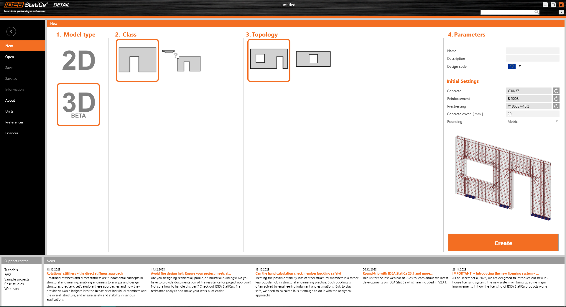
IDEA StatiCa Detail (3D Beta) is a solution that may be applied to assessing and analyzing out-of-plane stressed walls and for models consisting of different wall thicknesses. The solution represents an ideal compromise between an accurate solution using nonlinear methods but still simple modeling and calculation time.
Design
3D Detail is based on the verified and well-tested 2D Detail. It is still the same user environment, where most of the entities are kept to make working with the application as simple as possible.
The user can still model multiple wall elements using a template or import geometry from a .dxf file. In addition, in a 3D environment, they can set the wall eccentricity "ey" and also model walls with different thicknesses.
Reinforcement is defined in plane, similarly to 2D. However, there is an enhancement to define the position of the reinforcement layout over the wall thickness.
There is no possibility to define reinforcement perpendicular to the wall plane (stirrups).
Method
The approach used in IDEA Statica Detail (3D Beta) is based on the proven compatible stress field method (CSFM), which is adapted specifically for solving 3D tasks.
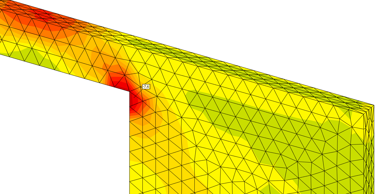
A special mesh formulation is applied to the wall structure to decrease the calculation time. Also, an orthotropic concrete material for walls has tensile (shear) resistance in the direction perpendicular to the wall plane. This advancement allows the calculation of the wall model without shear reinforcement defined over the thickness.
This applies specifically to the solution for walls. For the footing solution, it is not possible to transfer the tension in the concrete, but all the tension is captured by the reinforcement (even in the transverse direction). If you are interested in the 3D Detail for the footing solution, continue to the separate release note article).
Results
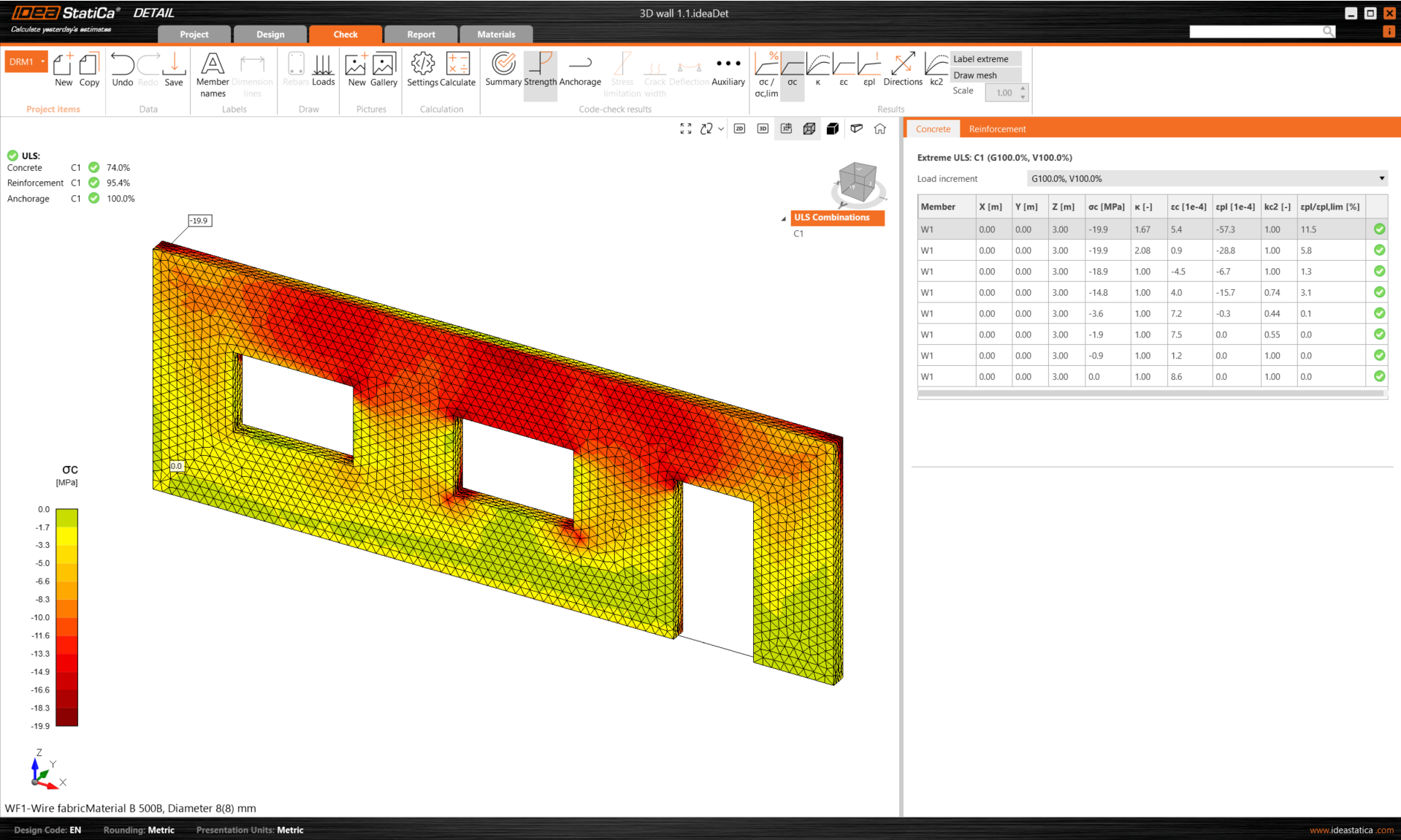
In the Results section, you will see three basic evaluations that are in line with the ULS criteria (ultimate limit state).
Stresses and strains related to concrete and reinforcement are defined in the section "Strength". The bond stresses and associated metrics are detailed in the "Anchorage" assessment. In addition, the non-linear deformation is provided under the "Auxiliary" checks.
We are giving you early access to this Beta version to try out for yourself while we continue putting it through its paces in our rigorous verification process. This is accessible to current users with the latest version and valid maintenance. If you fulfill the prerequisites, you can request free access by clicking the Beta Detail icon in the Connection app ribbon, which will take you to this landing page, where you complete the form and request to join the Beta program and get free access to 3D Detail.
Please be aware that the beta for the ACI code is currently unavailable.
Released in IDEA StatiCa version 24.0.
Take the latest IDEA StatiCa for a test drive today
Import of anchoring from Connection to Detail (BETA)
IDEA StatiCa 3D Detail has been out of the mode since version 24.1., see the updated article: RN 24.1: Import of anchoring from Connection to Detail.
Anchoring in a plain concrete block can be modeled and code-checked in IDEA StatiCa Connection. Sometimes it might be useful or necessary to reinforce the concrete block. Unfortunately, this capability isn't available within Connection.
However, with the development of 3D Detail (BETA), focused on anchoring into concrete blocks and analysis of both the anchoring elements and the concrete block itself, we have a solution. Moreover, a direct link is established between our Connection and Detail applications.
Connection users who design anchoring according to Eurocode can import their model from Connection to the advanced 3D Detail (BETA) by clicking one button.
How does it work?
- Import is allowed just for anchoring. If there is no concrete block in the model, the export to Detail button is disabled.
- The model in Connection has to be calculated. If results are not available, the export icon is disabled with the tooltip: "Results unavailable, calculate the model first"
- When the anchoring model has been calculated, the import button is enabled.
How to export anchoring from Connection to Detail?
First, create a model of anchoring in Connection according to Eurocode and click the Calculate button.
When results exist, export of footing is enabled. By clicking the button "Detail" in the ribbon, a dialog asking for the location and the name of the newly created Detail file appears.
After a successful export, the project in Detail is created. The geometry of the concrete block and the base plate, the position and properties of anchors, and the load are automatically transferred to Detail. Surface support placed at the bottom surface of the concrete block is automatically created.
The most tricky part of this process is the import of the load. For every calculated load effect in Connection, the corresponding load case and the ULS combination are automatically created in Detail.
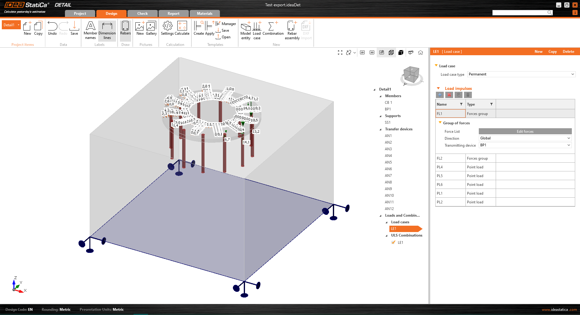
- The base plate is loaded by forces in welds, which are modeled as a Group of forces.
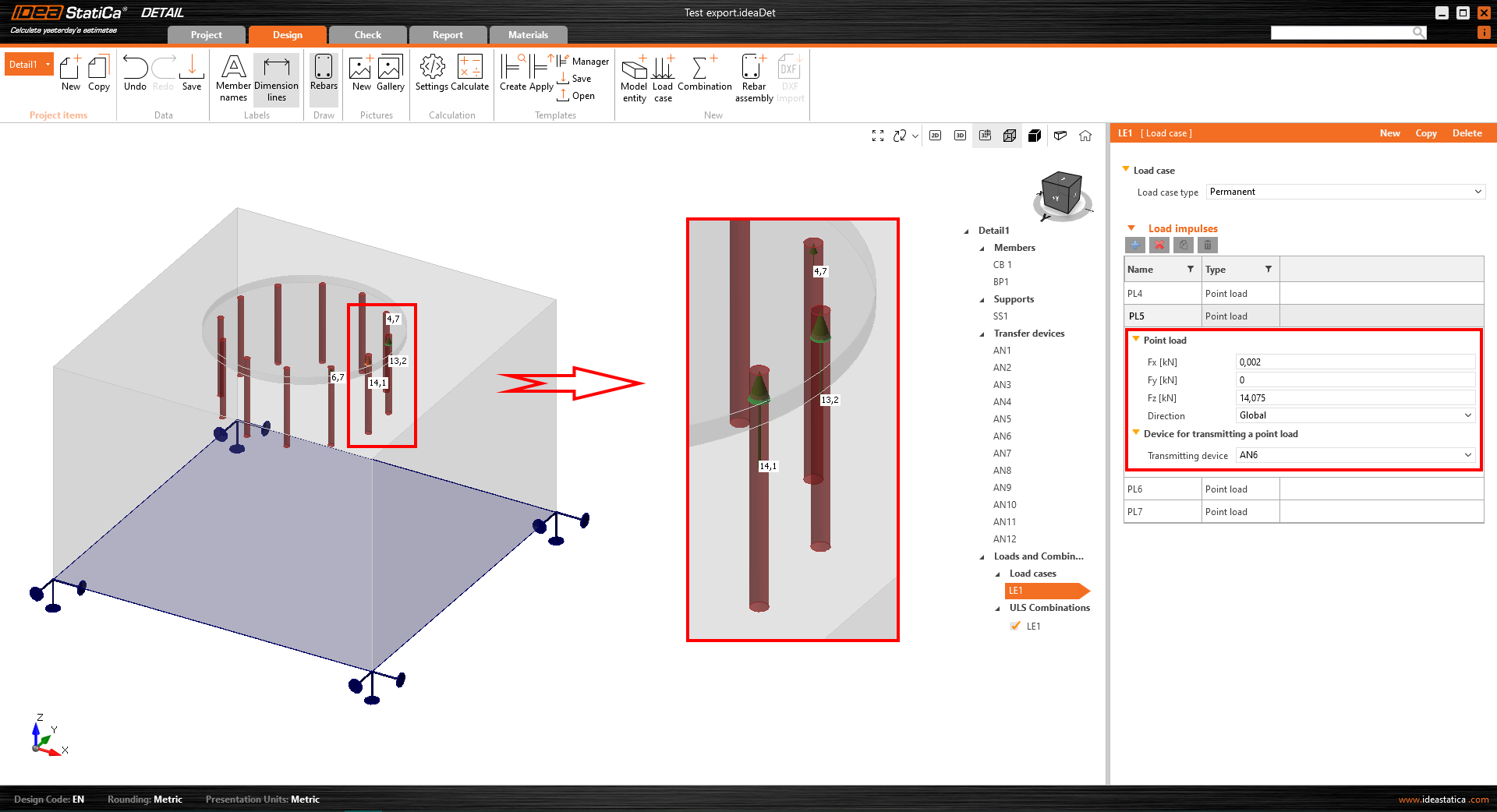
- Anchors are modeled and loaded independently from the base plate, and they are axially loaded by point loads. The anchor transmits only compression and tension.
- Shear is transferred by friction between the concrete block and the base plate.
When the model is imported from Connection app, the loading impulses are created automatically. The loading of anchors is represented in the scene by a double of arrows in opposite direction.
- One arrow represents the tension force acting only on the top of the anchor.
- The other one represents the compression force acting on the base plate
For the loading of the base plate itself, the imported loading is represented by a group of forces following the stresses in welds between the base plate and steel members in the Connection model.
The only step left is to add reinforcement and calculate the model.
Note: Code-checks in the 3D Detail are currently for the Eurocode (EN) only.
More about 3D Detail as a solution for anchoring in concrete can be found in a separate release note.
If your license doesn't contain the Detail app, take the opportunity and get the free Detail testing module added with full functionality.
Released in IDEA StatiCa version 24.0.
Take the latest IDEA StatiCa for a test drive today
Multiselect and multi-edit in Detail
The layout of Detail has been designed to give users easy and logical orientation within the properties. This ensures that navigating through the properties is intuitive and efficient.
When combined with the option of bulk editing the model entities, users can change multiple model entities simultaneously, saving time and streamlining their tasks.
Overall, this contributes to a smooth and productive user experience.
Bulk editing of model entities
This feature is mainly for users with projects containing a high amount of model entities and reinforcement. For example, after importing reinforcements from a DXF file, bulk editing allows editing properties like diameter, material, anchorage type, or layer definition for multiple items simultaneously.
A multi-selection shortcut allows the selection of multiple entities from the tree of entities by holding Ctrl+key or a combination of the Ctrl+Shift buttons.
The multi-selection option is also available for other properties (e.g., loads, combinations, and reinforcements). This feature lets users delete or copy selected entities simultaneously, enhancing efficiency and simplifying tasks.
Released in IDEA StatiCa version 24.0.
Take the latest IDEA StatiCa for a test drive today
Customizable report tab in Detail
Enhanced interaction with entities
The tree of entities, a central feature of the application, streamlines report customization. Entities within the tree correspond to specific report sections, with the content being adjustable through checkbox activations or deactivations. This design supports the intuitive reordering of report sections via drag and drop. At the same time, the selection of an entity instantly updates the property grid and highlights the selected section at the top of the interface.
Property Grid and report content management
Selected item properties are displayed in the Property Grid on the right side of the application, although not all entities possess properties. This setup provides a detailed overview and control over the report's content, ensuring relevant information is included as per user preference.
Transparent report generation
The Report tab aids in report generation, enhances transparency in calculations, and facilitates code checks. This includes:
- User paragraph incorporation: A "User Paragraph" can be incorporated into the report for the entire project or individual entities, utilizing an advanced editor for text and image manipulation reminiscent of MS Office tools. Changes are saved directly within the Report tab for convenience.
- Inclusion of additional essential sections: Sections like Theoretical Background and Software Information enrich the report, providing essential insights into calculation bases and software functionalities. The Theoretical Background section delves into calculation assumptions and model entity functionalities alongside code-check and design code references.
Multilingual support for theoretical background
Theoretical Background is accessible in English, German, Dutch, and Czech. For languages beyond these, an English version is provided to ensure wide accessibility.
Advanced Bill of Material features
Bill of Material (BOM) offers advanced features such as displaying rebar model entity names within the rebar table. This enhancement aids in effortlessly identifying rebars in the BOM, correlating them with their respective entities in the model. BOM also provides an option for the scheme to export reinforcement into dxf.
Released in IDEA StatiCa patch 23.1.5.
Take the latest IDEA StatiCa for a test drive today
RCS API for streamlined, simplified, and efficient design processes
The RCS API facilitates integration into any project framework with minimal prerequisites. The API is based on REST technology, and it supports clients for both .Net (C#) and Python, with the flexibility to extend support to additional programming languages.
Documentation, including installation instructions and example use-cases, is readily available on the developer website, providing comprehensive guidance for users to get started with the RCS API quickly:
The RCS API allows the loading of an RCS project by:
- Import from a created IOM file, or
- Opening an existing RCS file
Once an RCS project is active, you can:
- Get information about the project, including project data, available sections, and design members.
- Update code settings.
- Update the Reinforced cross-section reinforcement, tendons, or the entire cross-section using a template file (.nav).
- Run the calculation for all or selected sections.
- Retrieve results for all or selected sections.
The API marks our commitment to providing a scalable, user-friendly tool for the optimization and automation of concrete structural reinforced cross-section designs. This streamlines the design workflow and opens future advancements, including the consideration of web-based calculation services and integration with platforms like VIKTOR apps or Rhino Compute.
Released in IDEA StatiCa patch 23.1.3.
Take the latest IDEA StatiCa for a test drive today
Simple insertion of table inputs into IDEA StatiCa Detail
Users can use this streamlined process to mitigate the risk of manual entry errors and significantly accelerate data input, improving productivity. The procedure is as follows:
1. Initiate the process by selecting the first (top left) cell in the table input in IDEA StatiCa Detail. Press ESC after the first click to prepare the cell for new input.
2. Copy the desired table from any table sheet.
3. Paste (Ctrl+V) the copied table into the table within IDEA StatiCa Detail.
The Detail table will automatically adjust to match the dimensions of the Excel table.
This feature applies to all tables in IDEA StatiCa Detail, including those for Internal Forces and Reinforcement or Shape Definition, offering a much-needed solution for efficient and error-free data entry.
Released in IDEA StatiCa patch 23.1.2.
Download and try features of IDEA StatiCa 24.0
Comprehensive user interface in IDEA StatiCa Detail
View control options for both 2D and 3D scenes in IDEA StatiCa Detail
You can use the comprehensive control panel to seamlessly manipulate both 2D and 3D scenes within IDEA StatiCa Detail. This feature provides several display type options as well as the ability to zoom and move with the model.
The control panel offers three types of display control options:
- Positioning tools
- View options
- Visual presentation
Positioning tools, essential for adjusting the model's orientation to the preferred viewpoint, are conveniently located on the left segment of the control panel. This allows for intuitive and precise adjustments to the scene's layout.
Central to the panel, users can effortlessly toggle between 2D model, 3D model, and 3D real views, facilitating a fluid transition between different visualization modes to suit various analysis or presentation needs. More about the differences between the view options are described in General interface in Detail application.
On the right section of the panel, functionalities for altering the visual presentation of the model are available. Users can select between Solid and Transparent view options, which can also be integrated with a perspective view for enhanced depth and realism in model visualization.
A home button on the right side of the panel ensures easy navigation to the default view, enhancing user experience by providing a quick reset option.
This addresses key user requirements and pain points by incorporating the full suite of standard view control operations. It enables users to engage with the perspective view and interact with the scene without limitations, offering a comprehensive and unrestricted exploration of models.
The Information tab displays the selected Project item in a 3D transparent view
This is particularly useful when a user transitions from the Design/Tools/... tab to the Information tab as the currently active item will be automatically selected and displayed in this mode.
This is designed to facilitate easy navigation and orientation within Project items. By providing a 3D transparent view of the selected item, users can quickly understand the item's details, enhancing their ability to efficiently manage and interact with various project components.
Unification of dimensions across all graphical outputs
The unified dimension format significantly optimizes orientation within the 2D view, enhancing the overal user experience. The unified dimensions could be checked by cross-section diplaying via the CSS button on the Design tab‘s top ribbon.
Released in IDEA StatiCa patch 23.1.3.
Take the latest IDEA StatiCa for a test drive today
Presentation of relevant curve results in detailed graphs in IDEA StatiCa Detail
This is achievable through a combination of "Shift" + left mouse click or the right mouse click context menu. The displayed curve encompasses all calculated load increments for the chosen load case or combination. A specific load increment, as selected from the ribbon, is prominently marked on the chart.
The horizontal axis of the chart denotes the applied load, with symbols representing 100% of applied prestressing (P), permanent load (G), and variable load (V).
The system provides detailed insights into stresses, strains, deformation, crack width, and anchorage forces, among other parameters.
Additionally, you can export the data displayed in the chart into bitmap, CSV, or DXF formats. This option is accessible through the chart's context menu, allowing for further data analysis and documentation outside the software's environment.
Released in IDEA StatiCa patch 23.1.3.
Take the latest IDEA StatiCa for a test drive today
Unified Materials tab in Detail
The tab's user interface, which is unified with the rest of the application, presents a cohesive and streamlined design. The layout features the scene on the left side and the property grid on the right, which is aligned with the organization found in other application sections.
Key features include an intuitive exploration experience through:
- The tree of entities, where users can utilize the context.
- The menu by right-clicking an item.
- The option to wrap and unwrap individual sections for detailed examination.
Additionally, the tab offers the ability to easily view stress-strain diagrams for the steel used in bearing plates, providing an understanding of material properties directly within the interface.
Export functionality allows users to right-click any image in the scene to export diagrams in a variety of formats, facilitating documentation and reporting processes.
Scene control includes two diagrams for effective scene adjustments. A notable feature is also the ability to move the border between these graphs, providing users with great flexibility in customizing their view.
The user interface for the Materials tab prevents several potential critical challenges:
- Managing Diverse Materials: The tab simplifies the process of managing materials and cross-sections, which is particularly beneficial for rennovation projects, large-scale constructions, or research, ensuring a streamlined workflow.
- Complex Project Structures: Given the complexity of projects with numerous items and varied materials, the UI promotes efficiency and ease of navigation, making it easy to manage and review material properties and cross-sections.
Released in IDEA StatiCa patch 23.1.4.
Take the latest IDEA StatiCa for a test drive today
SIA 262:2013 implemented in RCS and Beam
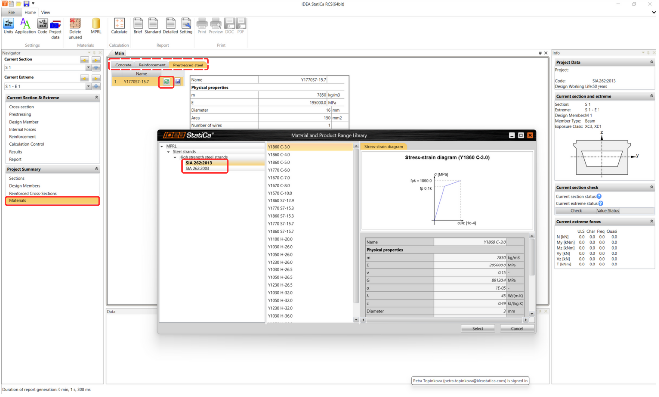
SIA 262:2013 can be selected when a new project is created and displayed in the project data and the standard is also listed in the final report. The implementation of SIA 262:2013 includes assessments, partial factors, and materials libraries.
Materials for concrete, reinforcement, and prestressing reinforcement can be found in the MPRL database, which is implemented in the IDEA StatiCa RCS and Beam applications.
Access is provided to materials for concrete, reinforcement, and prestressing reinforcement as defined in the most recent SIA 262:2013 standards, plus flexibility is maintained for users who prefer to work with the material specifications from the earlier SIA 262:2003 standards.
Due to our users' diverse needs and preferences, materials from SIA 262:2003 standards continue to be available, ensuring compatibility and flexibility for ongoing and legacy projects.
Released in IDEA StatiCa version 24.0.
Take the latest IDEA StatiCa for a test drive today
Accurate calculation of the shear resistance of slabs
The calculation of the resulting shear force was calculated in the past only according to the following formula:
\[{{v}_{d,max~}}=\sqrt{{{v}_{x}}^{2}+{{v}_{y}}^{2}}\]
Then, the maximal force was applied to all analyzed angles. In addition, the contribution of normal forces was taken into account only in the main axes directions and it could happen that the shear check was too conservative.
An illustrative example is shown in the figure above. A vertical uniform load qx and qy and a normal force in the x-axis direction only are specified. When recalculating the design forces, the maximum design shear force of 67.1 kN/m was considered for both principal directions, but the corresponding normal force for the 90° angle was zero. Since according to EN 1992-1-1, 6.2.2 (1) the normal compressive force affects the design shear capacity VRd,c through the value of σcp, the size of the shear capacity for an angle of 90° was based conservatively in this case.
Newly in IDEA StatiCa RCS, there are the angle corresponding to the direction of the resultant shear force (26.6°), the angle perpendicular to the direction of the resultant shear force(116.6)°, and the angle of the in-plane concrete strut. A corresponding shear force and other internal forces are assigned to these angles.
A critical shear check's angle is now different (26.6°). The results are more accurate with proper VRd,c, respectively σcp values.
This method accurately determines the direction of shear force and conducts code checks accordingly, aligning with the corresponding internal forces. You can find more information on how the internal forces are recalculated in the Theoretical Background for RCS - 2D sections.
If you are interested in designing concrete slabs and would like to know more about Baumman theory implemented in IDEA StatiCa RCS, try our webinar: Baumann's method for design of concrete shells in practice.
Released in IDEA StatiCa patch 23.1.2.
Take the latest IDEA StatiCa for a test drive today
BIM and Checkbot
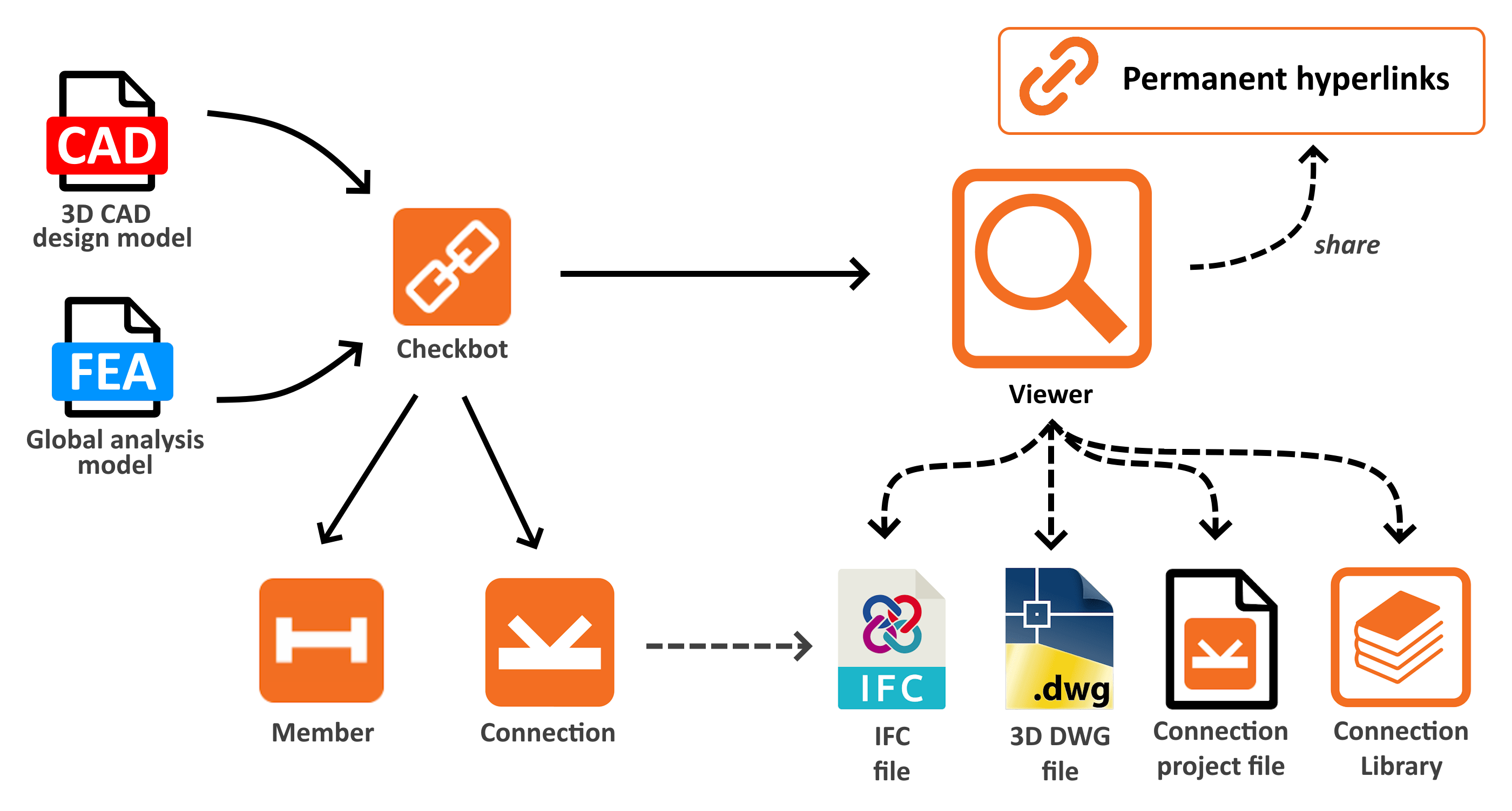
Checkbot Free – the structural design hub for FEA and CAD data
The IDEA StatiCa Checkbot Free application works both as a plugin linked to a specific FEA or CAD tool and as a standalone application capable of importing, managing, and exporting different types of design data. For the majority of its capabilities, the paid license is not necessary. The only necessity for running it is a valid IDEA StatiCa user account. This means that also without the paid, educational, or trial license, the user can still leverage the advantages of the Checkbot Free features.
Checkbot is a part of the IDEA StatiCa install file. If the user has not yet created an IDEA account, they can simply follow this step-by-step guide to set up a Basic account.
Checkbot Free offers a range of functionalities aimed at improving project collaboration and efficiency:
- Import compatibility: Users can import model data from all supported CAD and FEA tools directly into IDEA StatiCa Checkbot.
- Sharing of design objects: Enables sharing of design objects such as members' geometry, cross-sections, and materials.
From FEA tools, also the internal forces for specific load cases and combinations are imported together with the structure.
From CAD tools, the detailed connection elements are transferred with all additional plates, bolts and welds. - File-based import: Besides the automated way of integration and importing, Checkbot also provides a direct import option. The stand-alone version of Checkbot can process data from SAF, IOM and RAM files.
- File export: There is several possible outputs from Checkbot models, useful for sharing within communication. User can export
.ideaconfiles, which can be opened in Connection app or cloud Viewer. Or, IFC file format can be even more useful when reading by other free or licensed tools, especially handy for the CAD models. Both file formats can be exported as for the specific structural node or multiple nodes at once. - Viewer access: Allows opening selected connections in our Viewer web browser tool, ensuring project details are easily accessible for review and discussion.
If you're interested in all useful Checkbot's benefits, learn more in this comprehensive feature-explaining article.
User's benefits of being 'Free'
- Licensing flexibility: Checkbot is always included in a single IDEA setup package, where individual applications are being unlocked with a license. Checkbot tool is a 'Free' app working with all types of licenses. Even when all paid license seats are occupied, users can still perform imports and exports there.
- Replacement of free Viewer plugins: All the features provided by previous CAD viewer plugins for Advance Steel, Revit, and Tekla are now available in Checkbot feature set. Therefore, these plugins are not being developed and supported any more. All their advantages with many more can be found in Checkbot now.
- Unified solution: This also means that Checkbot centralized all the features useful for CAD tools users under one plugin button in the ribbon, one installation and one workflow.
Intuitive user experience
- Informative tooltips: In Free version, some features are disabled and available only in Paid licenses. These commands were improved by feature tooltips explaining why they are unavailable, enhancing user understanding and navigation.
- Clear identification: The free version is clearly labeled as "Checkbot Free" in the title, distinguishing it from the paid version.
Who is Checkbot free for?
Released in IDEA StatiCa version 24.0.
Take the latest IDEA StatiCa for a test drive today
RELATED ARTICLES
Checkbot ready for big projects
The ability to link IDEA StatiCa apps to dozens of different tools brings the need to create different approaches for specific vendors. The BIM link data transfer is polished and simplified to make the processes as smooth and quick as possible.
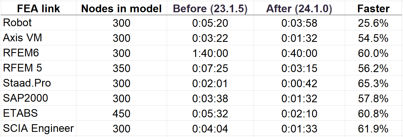
Thanks to this, the time needed for getting the data from different sources is short. Here are some comparisons for different metrics.
Faster imports for single connection from FEA links
We improved processes during the import of a single connection and member in FEA imports by reducing unnecessary API calls we use during import. This results in significantly faster import times for specific BIM links.
Faster opening of the existing projects
Also, the opening times for Checkbot's already existing projects has been improved by approximately 50% compared to version 23.1.5.
Faster FEA imports by 60%
The import speed has been improved by delaying connection creation (.ideacon) till the point where they are really needed. Import speedup varies from FEA link to FEA link.
During import, we skipped the part where all imported connections were written down to the hard drive in the Connections folder in the Checkbot project since it took the majority of import time. Starting from version 24.0.2 the Ideacon files are created at the moment when the user wants to interact with them:
- Design connections in IDEA StatiCa Connection
- Export connections to Viewer or to Ideaconn files from Checkbot
- Design connections in the Member application
Generating a subset of Ideacons only when necessary significantly reduces the time involved compared to creating hundreds of files during the import process. This approach accelerates, especially, the import of large models, allowing users to experience quicker performance and a more efficient workflow within IDEA StatiCa Checkbot.
Download the latest version of IDEA StatiCa and try all the features
Fast project visualization in Viewer
There are several major reasons why the Viewer is popular in communication between structural engineers, detailers, draftsmen, and contractors, including:
- Enhanced responsive 3D scene
- 3D model scales dynamically to fill the entire screen
- Pop-up messages – informing the user about ongoing processes
- Fast switching between Project items
- 3D dwg download processed in the background (the workspace is not blocked)
- Load effects are displayed in the navigation tree
Released in IDEA StatiCa version 24.0.
Take the latest IDEA StatiCa for a test drive today
Related articles
IDEA StatiCa Viewer scoring great at Tekla Developer Awards 2019
Enhanced 3D scene interaction and property management in Checkbot
Benefits for IDEA StatiCa Checkbot Users
- Multi-edit option for eccentricities: Users can edit the eccentricities of multiple elements simultaneously, significantly streamlining the modification process and enhancing their productivity.
- Enhanced readability for substructure elements: The visibility and readability of analyzed or related members within the Substructure part facilitate a better understanding and inspection of these components.
- Clear contrast for "read-only" properties: The property grid features a clear contrast for properties highlighted in red, providing good visibility of critical information and warnings.
Benefits for the entire platform
- Unified technology across applications: By having the same property grid technology across all IDEA StatiCa applications, maintenance and future extensions are straightforward, ensuring a consistent user experience.
- Powerful capabilities: The integration of this technology enables features such as multi-select and multi-edit capabilities, enhancing the flexibility of the applications.
Released in IDEA StatiCa version 24.0.
Take the latest IDEA StatiCa for a test drive today
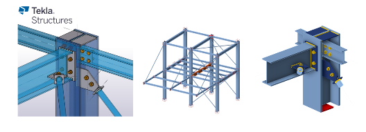
Tekla BimApi link available on GitHub
This Tekla BimApi brings about several key benefits for IDEA Statica Checkbot users, including:
- Unique naming for imported members: Names of imported members follow a consistent format of "Member + ID", ensuring clarity and preventing confusion in project management.
- Unified solution across BIM links: By standardizing the approach to BIM links, including the Tekla link, the solution's overall efficiency is maximized.
Accessibility
- Public GitHub repository: The Tekla link is accessible on GitHub at IDEA StatiCa Public GitHub Repository. This public availability fosters a community-driven approach to development and support.
- Enhanced support for third parties: With the BimApi link available on GitHub, third-party developers and partners implementing CAD to IDEA Checkbot integration can benefit from clear guidance, reducing the need for extensive assistance from the BIM team. Current integrations include Bocad, with potential future expansions to include Qnect.
Addressed Challenges
- Low development assistance costs: By providing a comprehensive and easily accessible resource on GitHub, the need for direct assistance from the BIM team is minimized, leading to significant time savings.
- Clarification of design member naming: The unique naming convention for imported members addresses potential user confusion regarding the identification of design members within Checkbot.
User Experience (UX):
The development process for new CAD links to IDEA StatiCa Checkbot is seamless, making it straightforward and non-time-consuming for developers.
Released in IDEA StatiCa version 24.0.
Take the latest IDEA StatiCa for a test drive today
Usability and Licensing
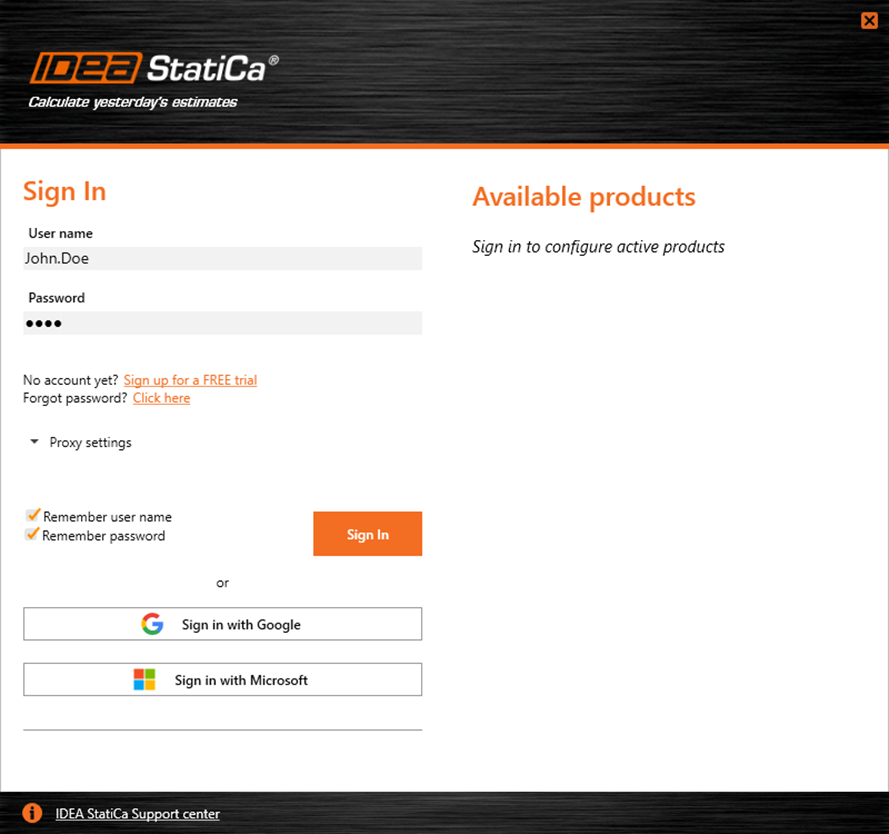
Single Sign-on (SSO)
Single Sign-on authentication enables centralized authentication. With this feature, users can enjoy direct access to all IDEA StatiCa applications using a single set of login credentials. This simplifies the login process, providing a smooth user experience by eliminating the hassle of managing multiple passwords.
Single Sign-on facilitates access, enhances security, and boosts customer productivity, without the need to remember passwords. It empowers users to access both desktop and web applications and improves access management for company license admins.
Released for IDEA StatiCa versions 22.1.6, 23.1.5, 24.0.6 and 24.1.
Download the latest version of IDEA StatiCa and try all the features
Enhanced User Portal
Key features of the User portal environment
- User-oriented content is shown on the main platform.
- Clear communication of expired licenses.
- A clear dashboard with important data in one place
- Account details
- Reseller info
- Easy-to-use helpdesk cases management
- Access to courses of IDEA StatiCa e-learning platform available here.
- The side menu also makes it easy to
- Browse through License analytics with the product usage overview
- Access the cloud tools Connection Library and Viewer
Released in IDEA StatiCa version 24.0.
Besides administration purposes, there are links to IDEA cloud tools present there as well.
Take the latest IDEA StatiCa for a test drive today
Shared Preferences across the whole tool range
The Preferences dialogue can be accessed from the starting IDEA StatiCa app or in a backstage menu of each listed app. Once the changes in preferences are saved, they will be applied to all other apps.
Embedding this feature ensures the following experience:
- Consistent settings across all the apps
- Simplification of users' workflows
- Ability to set all the shared preferences in one place for all the tools at once
An example of usage is defining the default Design code and subcode in the Preferences dialog, causing these parameters to be predefined for all new projects.
More about material defaults for the current project in the Connection app in the article Project item and material management.
How to set the Default state
There are two ways to restore the parameters to their default settings. The default values are prepared in two versions: Imperial and Metric.
1) Reset the whole list of preferences
2) Reset just the specific category
When starting in Checkbot
This integration ensures that settings defined in Checkbot are automatically applied and recognized in the Connection, Detail, and Member items opened within the same Checkbot project, promoting efficiency and reducing the need for manual reconfiguration.
The advantages of shared preferences are currently available for Connection, Member, Detail, and Checkbot applications. The set of preferences available in the dialogue is continuously extended.
Released in IDEA StatiCa version 24.0.
Sharing of preferences via Export/Import
Users can Export and Import the whole preferences set or just a part of it via a .json file and share it with colleagues.
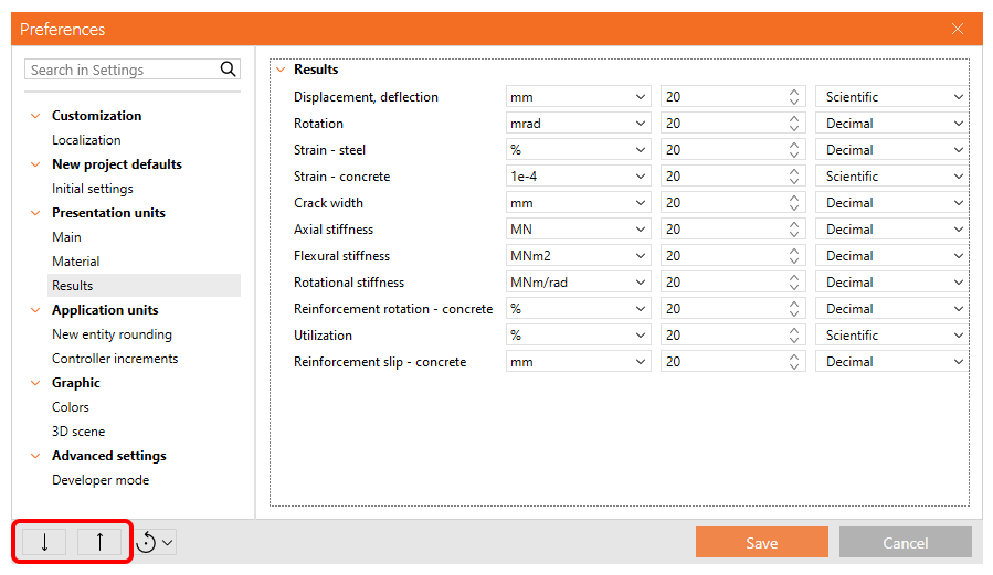
To export and import all preferences, select the appropriate icons in the bottom left corner of the dialog.
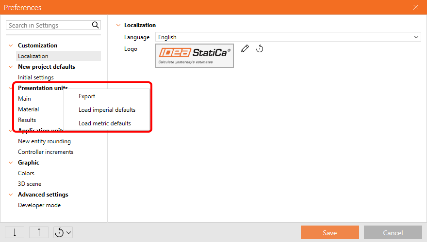
To export and import only one chapter of the preferences, a context menu is available when you right-click the chapter in the menu.
Released in IDEA StatiCa version 24.1.
Download the latest version of IDEA StatiCa and try all the features
Error handling with Support Center integration
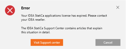
This troubleshooting service is designed to provide immediate assistance for license-related issues encountered by users of the IDEA StatiCa desktop application with links to solutions or additional information.
The desktop application can overcome any occurrence of crash issues by providing clear communication to the user about the cause of the error and the recommended action to resolve the issue – specifically, updating the IDEA StatiCa application. This approach ensures users are well-informed about the steps they can take to avoid future problems, thereby enhancing the user experience by offering direct guidance on how to proceed in the event of an application crash.
The error-handling tool offers explanations about what is going on during technical or licensing issues and provides direct links to articles where the solution is explained in a more comprehensive way.
Integration with the Support centre
Users are equipped with the knowledge to understand the causes behind errors within the desktop application. Upon encountering an error, they are directed to a specific section of the Support Center through a direct link, where users can access solutions and detailed information pertaining to their issue.
Faster solution identification
This integration addresses several different types of situations:
- Known licensing issues – linking the user to specific knowledge base articles.
- Known technical issues that are already solved – linking the user to the current installation setups.
- Known technical issues that have already been reported – informing about no need for further actions.
This not only aids in error resolution but also enhances the user experience by providing targeted support, directly addressing the causes of common issues encountered within the application.
Released in IDEA StatiCa patch 23.1.3.
Take the latest IDEA StatiCa for a test drive today
In-app tooltips and links with Support Center
Feature tooltips provide direct access to Support Center articles right from the desktop application, resulting in finding quicker answers and reducing the need for contacting technical support.
Users can support and educate themselves immediately regarding frequently asked topics. The tooltip stays displayed on mouseover on the tooltip itself, not just the icon.
This reduces the time necessary for users to self-help when they are uncertain about how the features work. The hyperlinks are maintained to give the user the best possible information from the knowledge base article library.
Released in IDEA StatiCa version 24.0.
Take the latest IDEA StatiCa for a test drive today
Keyboard shortcuts (hotkeys) in IDEA StatiCa apps
Available keyboard shortcuts:
- Save (Ctrl + S): Initiates the "Save" function for projects that have been previously saved. For new projects, it opens the "Save as" dialog.
- Undo (Ctrl + Z): Performs a single undo step, allowing users to revert the last actions in steps.
- Redo (Ctrl + Y): Enables a single redo step, facilitating the reapplication of the most recently undone action.
- Open Project (Ctrl + O): Launches the "Open browser" in the backstage menu, displaying also the list of recent projects for quick access.
- New Project (Ctrl + N): Launches the "New project" in the backstage menu, to start a new project file. It does not create a new project item within the current project.
- Rename (F2): Allows to rename the currently selected item in the project tree, providing a quick way to organize and identify project components.
Released in IDEA StatiCa version 24.0.
Take the latest IDEA StatiCa for a test drive today
New Portuguese (Brazilian) language in apps
Portuguese (Brazilian) has been added to the language set across all applications.

