Code-check of welds (EN)
Fillet welds are checked according to EN 1993-1-8. The strength of butt welds is assumed the same as the base metal and is not checked.
Fillet welds
Design resistance
The plastic redistribution in welds is used to automatically avoid the stress singularities in weld elements to redistribute the stress further along the weld length. The strength of the weld approximately matches the hand calculation, and the stress is correctly distributed for complicated issues like welding to an unstiffened flange (EN 1993-1-8 – Cl. 4.10). The stress in the throat section of a fillet weld is determined according to EN 1993-1-8 Cl. 4.5.3. Stresses are calculated from the stresses in weld element. Bending moment around the longitudinal weld axis is not taken into account.
\[ \sigma_{w,Ed}=\sqrt{\sigma_{\perp}^2 + 3 \left ( \tau_{\perp}^2 + \tau_{\parallel}^2 \right )} \]
\[ \sigma_{w,Rd} = \frac{f_u}{\beta_w \gamma_{M2}} \]
Weld utilization
\[ U_t = \min \left\{ \frac{\sigma_{{w,Ed}}}{\sigma_{w,Rd}}, \frac{\sigma_{\perp}}{0.9 f_u / {\gamma_{M2}}} \right\} \]
where:
- σw,Ed – equivalent stress in the weld
- σw,Rd – weld resistance
- βw – correlation factor (EN 1993-1-8 – Table 4.1)
- fu – ultimate strength, chosen as the lower of the two connected base materials or according to material chosen by user
- γM2 – safety factor (EN 1993-1-8 – Table 2.1; editable in Code setup)
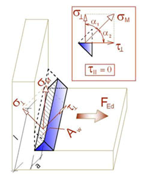
- σ┴, τ┴, τ‖ – stresses in weld according to the figure below:
All values required for check are printed in tables. Ut is the utilization of the most stressed element. Since plastic redistribution of stress in weld is used, it is the decisive utilization. Utc provides information about utilization along the weld length. It is the ratio of actual stress at all elements of the weld to the design resistance of the stress of the whole length of the weld.
The equivalent stress in the weld diagram shows the following stress:
\[ \sigma = \max \left \{ \frac{\sigma_{\perp}}{0.9 \beta_w}, \, \sqrt{\sigma_{\perp}^2 + 3 \tau_{\perp}^2 + 3 \tau_{\parallel}^2} \right \} \]
Butt welds
Welds can be specified as butt welds. Complete joint penetration is considered for butt welds, and therefore such welds are not checked.
Detailing
Minimum plate thickness of welded connections are checked according to EN 1993-1-8 – 4.1(1):
- For hollow steel section, the plate thickness should be at least 2.5 mm
- For other plates, the plate thickness should be at least 4 mm
Maximum weld throat thickness of fillet welds is checked for parallel plates. An error is issued, such weld is not feasible due to geometric constraints.
Minimum weld throat thickness of fillet welds should be at least 3 mm according to EN 1993-1-8 – 4.5.2(2). An error is issued when this requirement is not satisfied.
A warning is issued when weld throat thickness is smaller than the requirement in DIN EN 1993-1-8 – NA to 4.5.2:
\[a \le \sqrt{t_{max}}-0.5\]
where:
- \(a\) – weld throat thickness
- \(t_{max}\) – thickness of the thicker connected plate
- units must be in [mm]
Infomation is issued when weld throat thickness is smaller than the requirement for minimum ductility of welded joints in FprEN 1993-1-8:2023 – 6.9(4). This requirement is checked for double-sided fillet welds by:
\[a/t=\frac{\beta_w\gamma_{M2} f_y}{\sqrt{2} f_u \gamma_{M0} } \cdot \min \left \{1.0, 1.1\frac{f_y}{f_u} \right \}\]
where:
- \(a\) – weld throat thickness
- \(t\) – thickness of the plate connected by edge
- \(\beta_w\) – weld correlation factor
- \(\gamma_{M2}\) – safety factor for bolts and welds; editable in Code setup
- \(f_y\) – plate yield strength
- \(f_u\) – weld ultimate strength
- \(\gamma_{M0}\) – safety factor for plates; editable in Code setup
The weld throat thickness for single-sided fillet weld is twice larger than that for double-sided fillet weld.


