IDEA StatiCa introduces Detail (3D Beta) for solving 3D tasks such as anchoring in concrete blocks. The solution lets you perform the design without oversimplification and obtain checks based on the Ultimate Limit State (ULS). The method implemented in IDEA Statica Detail (3D Beta) is based on the already proven Compatible Stress Field Method, which was adjusted to be able to solve 3D problems (tri-axial stress). Also, the basic element is modified to the third dimension. The solid block is the basic element representing concrete and can be deformed in all three directions. To make it possible to create a complex model for footings, we have implemented entities such as surface support, base plate, anchors, and more. All these entities are described, as well as their functionality, in the following article.
The shape of the solid block
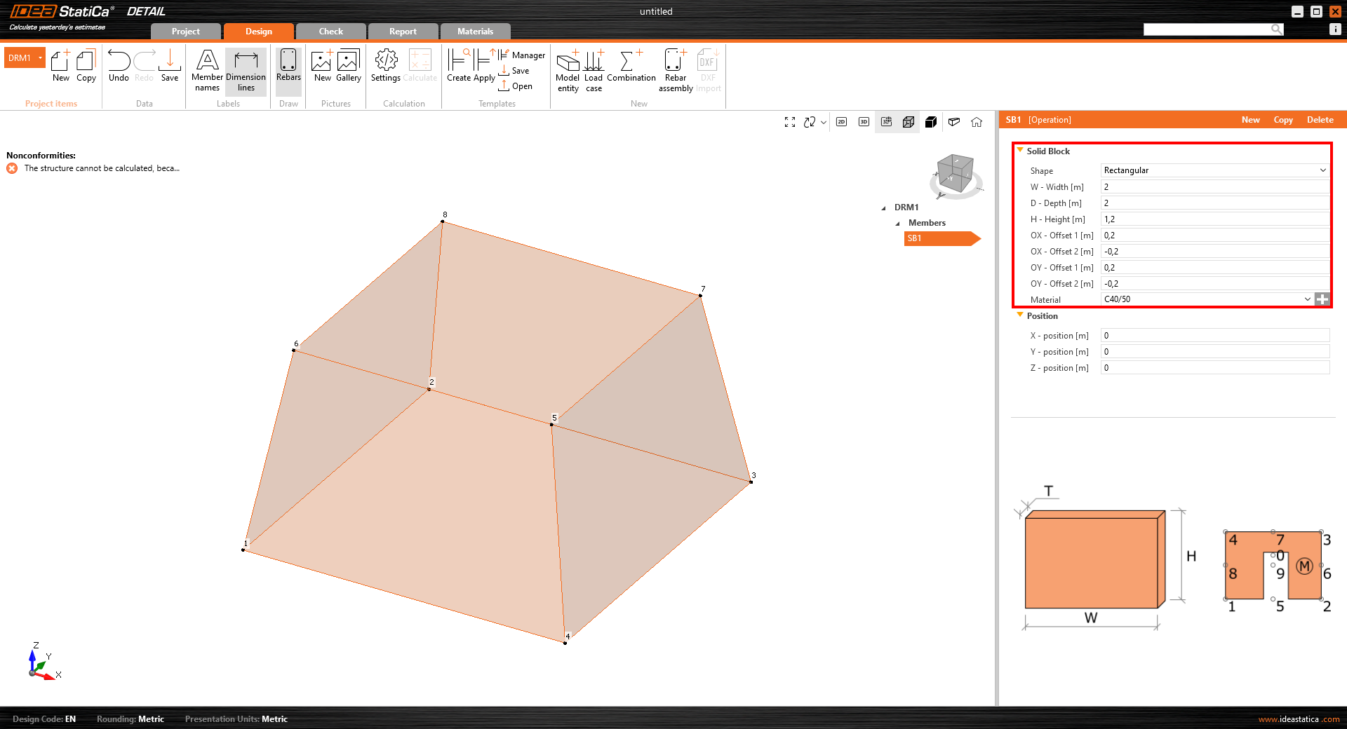
Concrete block can be modeled thanks to the member type called "Solid block", whose geometry can be defined in two ways:
- Rectangular shape – This option is suitable for defining the footing with a rectangular base and constant height. Defining offsets for all sides of the block also allows sloped footing to be modeled.
- Polygonal base with a defined height – The second option for defining a footing shape is the definition of the base shape as a general polygon. However, it is not possible to create sloped footing as described in the previous option.
Surface supports
Surface support is the only possible support type that can be defined for the solid model. There are two options for the shape definition – it can be defined either for the whole surface or as a general area whose outline is determined by polyline.
The advantage of surface support is the possibility of defining stiffness and setting non-linear behavior that simulates contact with the soil. Supports defined by general shape (polyline) can be used to simulate piles.
Load transfer devices
Especially for the anchoring, two entities to transfer loads were developed:
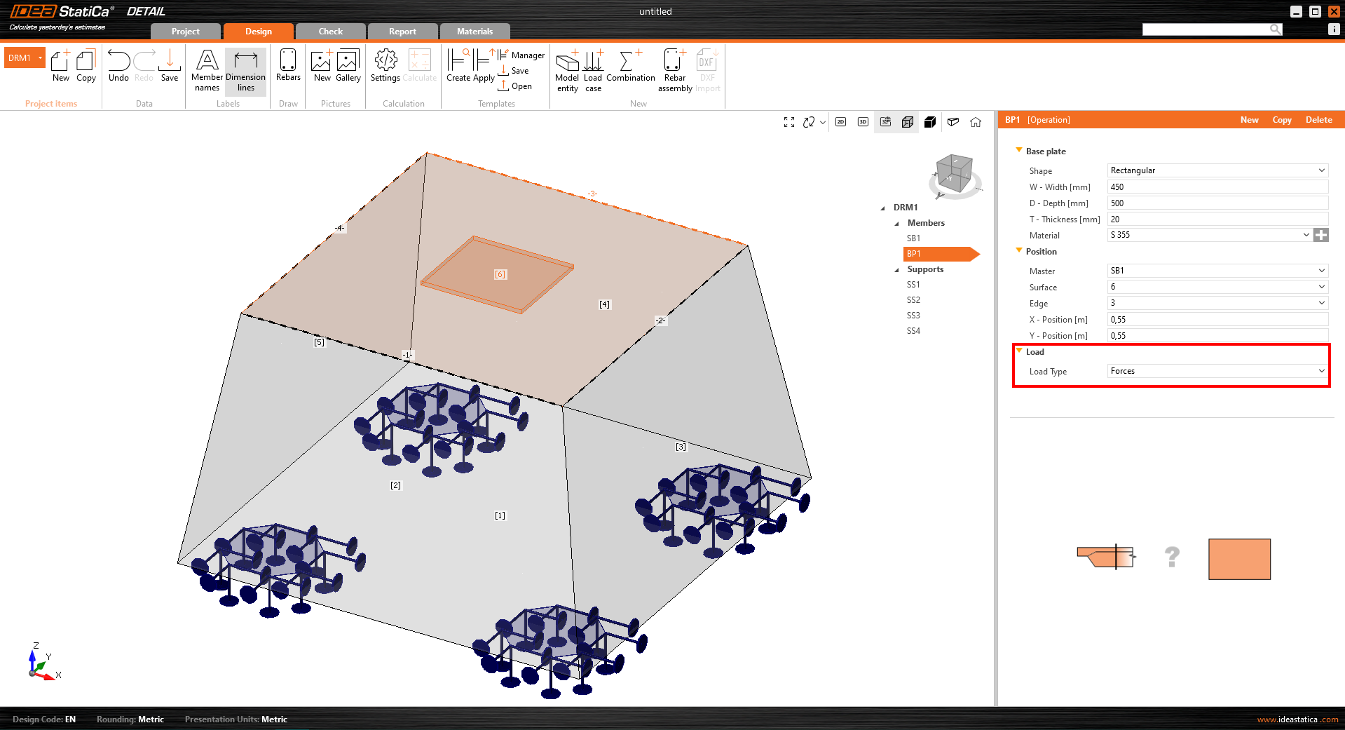
- Base Plate – The shape of the base plate can be defined as a rectangle or a general polyline. The base plate can be modeled with the part of the column (option “Load transfer – Column”) or without the column (option “Load transfer – Forces”). When option “Load transfer – Forces” is selected, the defined load is applied directly to the base plate. When the steel column is defined (by its cross-section and length), the load is applied to the top of the column, and its stiffness helps distribute the stress correctly to the base plate.
- Single Anchor – A single anchor is a 1D element allowing the transfer of axial load. The anchor can be automatically interconnected with the base plate or it can be loaded directly by the point load*.
*There are several limitations for anchors in BETA.
The anchor transmits only compression and tension. Shear, if imported from Connection, is transferred by friction between the concrete block and the base plate. Only axial force can be applied to the anchor.
There are two different types of anchors available in the Detail app:
- Cast-in place – Reinforcement
- Adhesive anchor
For Adhesive anchor, there is another parameter coming into the analysis – Bond strength. This value is set by default to 2 MPa and should be adjusted by the user according to the datasheet info from the anchor manufacturer.
Loads
Adding a group of forces and surface load is essential for ease of use. In total, we support three load types:
- Surface load – Surface load can be applied to any concrete surface. It can be applied to the whole surface or just on its part over a certain area, which is determined by its outline (polyline).
- Point load
- Group of forces – A group of forces is an entity that defines several point loads acting as a group. It can be applied on the base plate or the concrete surface. This load type can be used to simulate forces in welds transferring stresses from the column to the base plate.
Reinforcement
A new type of reinforcement was developed, allowing the reinforcement of a footing to be sufficiently reinforced. A Group of bars provides several options for the definition of the rebars:
- By two points
- On surface edge – On surface edge – a reinforcement layer is created parallel to the selected surface. The user defines several bars in a layer and a number of layers parallel to the selected surface.
- On surface edge or more edges – On surface edge or more edges allow the modeling of layers of rebar with a complex shape (plane curve related to any concrete surface). The layer is, therefore, determined just by one rebar. However, several parallel layers can be defined. Concrete cover can be defined independently for each edge. This is the best option to model stirrups.
- On polyline
Results
Within the results tab, you'll discover three fundamental assessments in accordance with ULS (Ultimate Limit State).
Results of stresses and strains in concrete and reinforcement are presented in the section "Strength". Bond stress and related values are found in the "Anchorage" check. A very important value of non-linear deformation is presented in the "Auxiliary" check.
3D BETA version limitations
The goal of the released BETA version is to give our users the opportunity to get familiar with it, test the solution, and give us feedback. To clarify the expectations from the BETA version of 3D Detail, there are some limitations in the current version:
- There is no shear force transfer in anchors – shear is transferred only by friction between the base plate and the concrete block surface.
- Results of the analysis and code-checks are limited to ULS (ultimate limit state)
- The calculation time of a single model of a concrete block and base plate with an anchor grid may take up to 10 minutes
- Sections for the visualization of results will be available in BETA 2
- Self-weight of model elements is not taken into account
- Only one solid concrete block can be used in the model
The 3D solution for Detail is undergoing intensive development and the verification process. With version 24.0, the first BETA of 3D Detail is released, BETA 2 is expected in July 2024 with improvements in results' interpretation, reducing the current limitations' list and bringing additional features. The BETA of 3D Detail will be transferred to the ALPHA version after completing a thorough verification process and released with version 24.1.
Model description and verifications
To learn more about the 3D Detail analytical model, read the theoretical background article:
Furthermore, the first verifications of the 3D Detail model and results have been published in the following articles:
- 3D Detail Verification: Simple Bend Test
- 3D Detail verification: Anchor test
- 3D Detail verification: Shear tests in beams with low amounts of stirrups
Also, you can refer to the Detail theoretical background articles that are both for 2D and 3D models regarding the finite elements and ULS results interpretation:
We are giving you early access to this Beta version to try out for yourself while we continue putting it through its paces in our rigorous verification process. This is accessible to current users with the latest version and valid maintenance. If you fulfill the prerequisites, you can request free access by clicking the Beta Detail icon in the Connection app ribbon, which will take you to this landing page, where you complete the form and request to join the Beta program and get free access to 3D Detail.
Note: Code-checks in 3D Detail are currently for Eurocode (EN) only.


