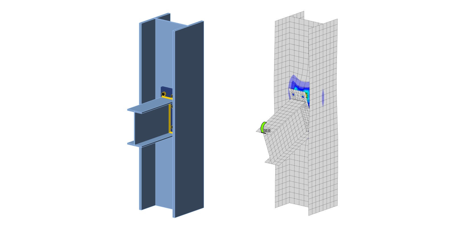
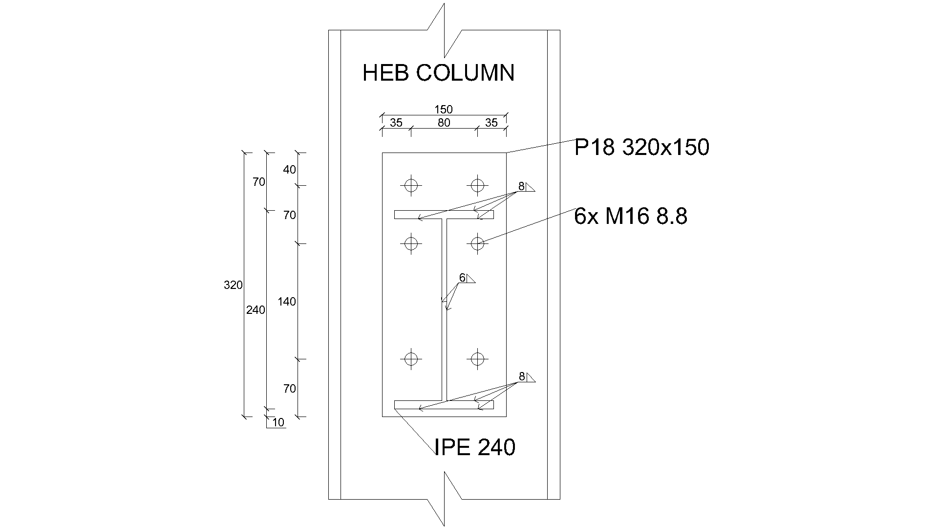
描述 梁柱节点的CBFEM(基于组件的有限元模型)模型通过组件法(CM)进行验证。带三排螺栓的扩展端板与柱腹板相连,并承受弯矩荷载;见图 5.3.1。
Fig. 5.3.1 Joint geometry - all dimensions in mm \textsf{\textit{\footnotesize{Fig. 5.3.1 Joint geometry - all dimensions in mm}}} Fig. 5.3.1 Joint geometry - all dimensions in mm
分析模型 控制节点行为的三个组件为:受弯端板、受拉和受压梁翼缘,以及受弯柱腹板。端板及受拉和受压梁翼缘按 EN 1993-1-8:2005 进行设计。柱腹板受弯行为依据(Steenhuis 等,1998)进行预测。梁柱弱轴节点试验结果(如 Lima 等,2009)表明,该类型节点在连接梁平面内受荷时具有良好的预测精度。
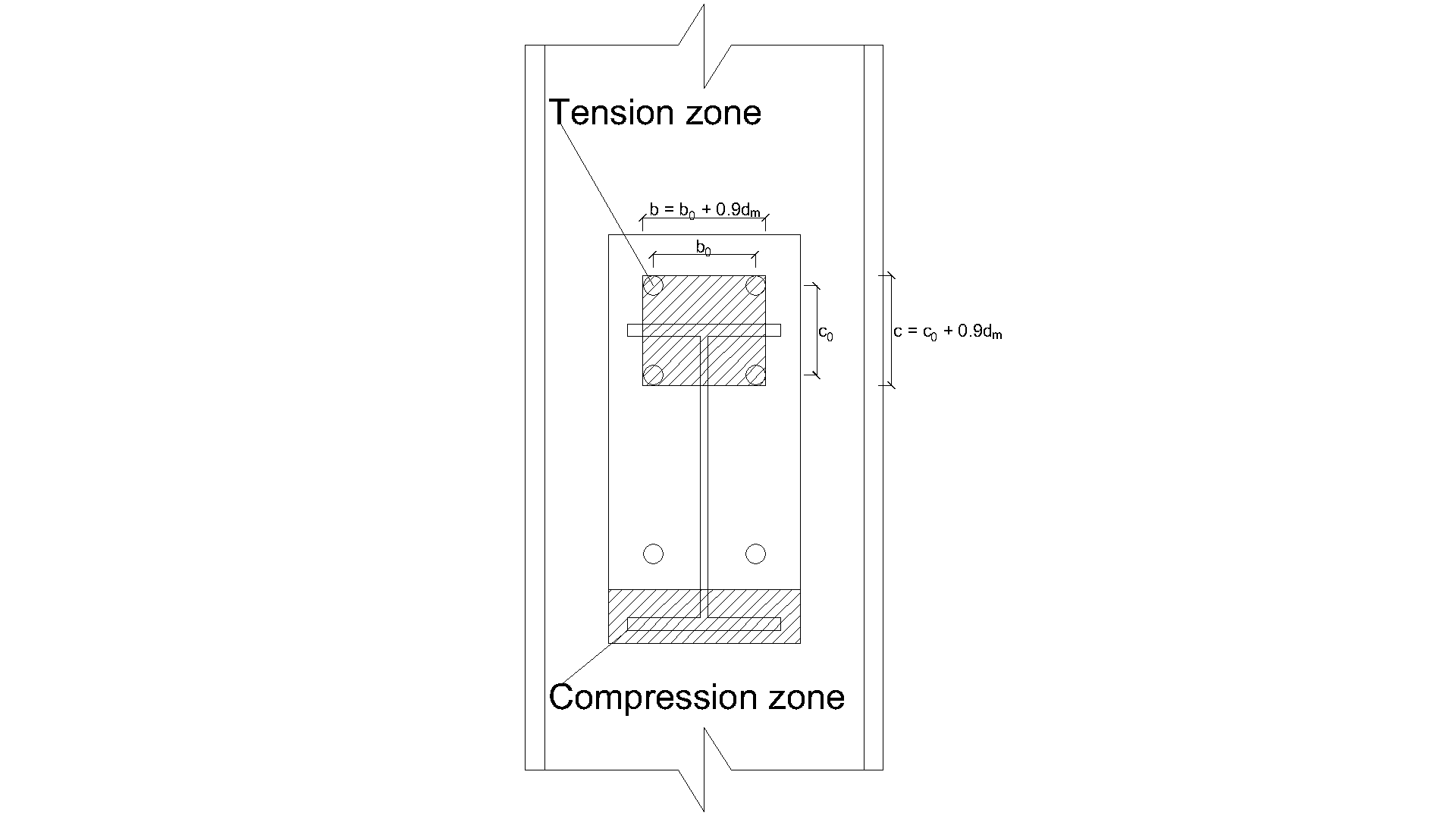
Fig. 5.3.2 Definition of the tension zone \textsf{\textit{\footnotesize{Fig. 5.3.2 Definition of the tension zone}}} Fig. 5.3.2 Definition of the tension zone
F l o c a l . R d = min ( F p u n c h . R d ; F c o m b . R d ) F_\mathrm{{local.Rd }}=\min \left(F_\mathrm{{punch.Rd }} ; F_\mathrm{{comb.Rd }}\right) F local.Rd = min ( F punch.Rd ; F comb.Rd )
F p u n c h . R d = n ⋅ π ⋅ d m ⋅ t w c ⋅ f y / ( 3 ⋅ γ M 0 ) bolted end plate F_\mathrm{ {punch.Rd }} = n \cdot \pi\cdot d_\mathrm{m} \cdot t_\mathrm{w c} \cdot f_\mathrm{y} /\left(\sqrt{3} \cdot \gamma_\mathrm{M 0}\right) \quad \text{bolted end plate } F punch.Rd = n ⋅ π ⋅ d m ⋅ t wc ⋅ f y / ( 3 ⋅ γ M0 ) bolted end plate
b = b 0 + 0.9 ⋅ d m b = b_0 + 0.9 \cdot d_\mathrm{m} b = b 0 + 0.9 ⋅ d m
c = c 0 + 0.9 ⋅ d m c = c_0 + 0.9 \cdot d_\mathrm{m} c = c 0 + 0.9 ⋅ d m
a = L − b a = L - b a = L − b
k = 1 if ( b + c ) / L > 0.5 k= 1 \quad \text{ if }\quad(b+c) / L>0.5 k = 1 if ( b + c ) / L > 0.5
k = 0.7 + 0.6 ( b + c ) / L if ( b + c ) / L ≤ 0.5 k=0.7+0.6(b+c) / L \quad \text{ if }\quad(b+c) / L \leq 0.5 k = 0.7 + 0.6 ( b + c ) / L if ( b + c ) / L ≤ 0.5
b m = L [ 1 − 0.82 t w c 2 c 2 ( 1 + 1 + 2.8 c 2 t w c L ) 2 ] , but b m ≥ 0 b_\mathrm{m}=L\left[1-0.82 \frac{t_\mathrm{w c}^2}{c^2}\left(1+\sqrt{1+2.8 \frac{c^2}{t_\mathrm{w c} L}}\right)^2\right], \quad \text{ but } \quad b_\mathrm{m} \geq 0 b m = L 1 − 0.82 c 2 t wc 2 1 + 1 + 2.8 t wc L c 2 2 , but b m ≥ 0
x 0 = L ⋅ [ ( t w c L ) 2 3 + 0.23 c L ( t w c L ) 1 3 ] ⋅ ( b − b m L − b m ) x_0=L\cdot\left[\left(\frac{t_\mathrm{w c}}{L}\right)^{\frac{2}{3}}+0.23 \frac{c}{L}\left(\frac{t_\mathrm{w c}}{L}\right)^{\frac{1}{3}}\right] \cdot\left(\frac{b-b_\mathrm{m}}{L-b_\mathrm{m}}\right) x 0 = L ⋅ [ ( L t wc ) 3 2 + 0.23 L c ( L t wc ) 3 1 ] ⋅ ( L − b m b − b m )
x = 0 b ≤ b m x = 0 \quad b \leq b_\mathrm{m} x = 0 b ≤ b m
x = − a + a 2 − 1.5 a c + 3 2 t w c [ π L ( a + x 0 ) + 4 c ] if b > b m x=-a+\sqrt{a^2-1.5 a c+\frac{\sqrt{3}}{2} t_\mathrm{w c}\left[\pi \sqrt{L\left(a+x_0\right)}+4 c\right]} \quad \text{ if }\quad b>b_\mathrm{m} x = − a + a 2 − 1.5 a c + 2 3 t wc [ π L ( a + x 0 ) + 4 c ] if b > b m
F c o m b . R d = k ⋅ t w c 2 ⋅ f y [ π L ( a + x ) + 2 c a + x + 1.5 c x + x 2 3 t w c ( a + x ) ] / γ M 0 F_\mathrm{c o m b . R d}=k\cdot t_\mathrm{w c}^2 \cdot f_\mathrm{y}\left[\frac{\pi \sqrt{L(a+x)}+2 c}{a+x}+\frac{1.5 c x+x^2}{\sqrt{3} t_\mathrm{w c}(a+x)}\right] / \gamma_\mathrm{M 0} F comb.Rd = k ⋅ t wc 2 ⋅ f y [ a + x π L ( a + x ) + 2 c + 3 t wc ( a + x ) 1.5 c x + x 2 ] / γ M0
ρ = 1 if z / ( L − b ) ≤ 1 \rho = 1 \quad \text{ if }\quad z / (L-b) \leq 1 ρ = 1 if z / ( L − b ) ≤ 1 ρ = z / ( L − b ) if 1 < z / ( L − b ) ≤ 10 \rho = z / (L-b) \quad \text{ if }\quad 1<z / (L-b) \leq 10 ρ = z / ( L − b ) if 1 < z / ( L − b ) ≤ 10
F g l o b a l . R d = F c o m b . R d 2 + t w c 2 f y 4 ( 2 b z + π + 2 ρ ) / γ M 0 F_\mathrm{g l o b a l . R d}=\frac{F_\mathrm{c o m b . R d}}{2}+\frac{t_\mathrm{w c}^2 f_\mathrm{y}}{4}\left(\frac{2 b}{z}+\pi+2 \rho\right) / \gamma_\mathrm{M 0} F global.Rd = 2 F comb.Rd + 4 t wc 2 f y ( z 2 b + π + 2 ρ ) / γ M0
F R d = min ( F l o c a l . R d ; F g l o b a l . R d ) F_\mathrm{Rd} = \min \left(F_\mathrm{{local.Rd }} ; F_\mathrm{g l o b a l . R d}\right) F Rd = min ( F local.Rd ; F global.Rd )
M R d = z ⋅ F R d M_\mathrm{Rd} = z \cdot F_\mathrm{Rd} M Rd = z ⋅ F Rd
其中:
t w c t_\mathrm{w c} \quad t wc 为柱腹板厚度
f y f_\mathrm{y} \quad f y 为柱腹板屈服强度
γ M 0 \gamma_{\mathrm{M} 0} γ M 0 为钢材分项安全系数
γ M 0 \gamma_{\mathrm{M} 0} γ M 0 为钢材分项安全系数
d m d_\mathrm{m} d m 螺栓头对角线直径
F p u n c h . R d F_\mathrm{ {punch.Rd }} \quad F punch.Rd 为抗冲切剪力承载力
F c o m b . R d F_\mathrm{ {comb.Rd }} \quad F comb.Rd 为冲切、剪力与弯矩组合作用承载力
数值模型 评估基于 EN 1993-1-5:2006 规定的最大应变限值 5%。有关CBFEM(基于组件的有限元模型)模型的详细信息见第 3 章。
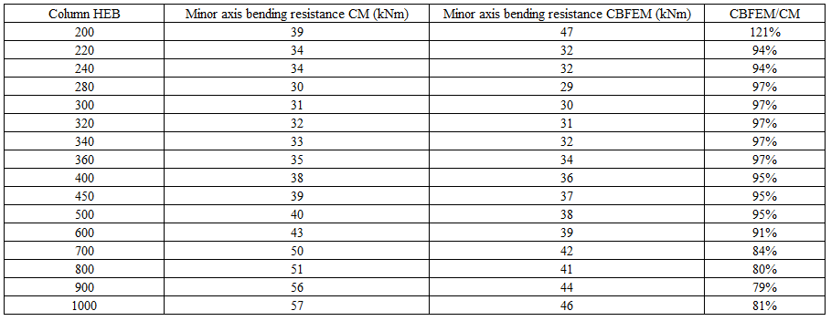
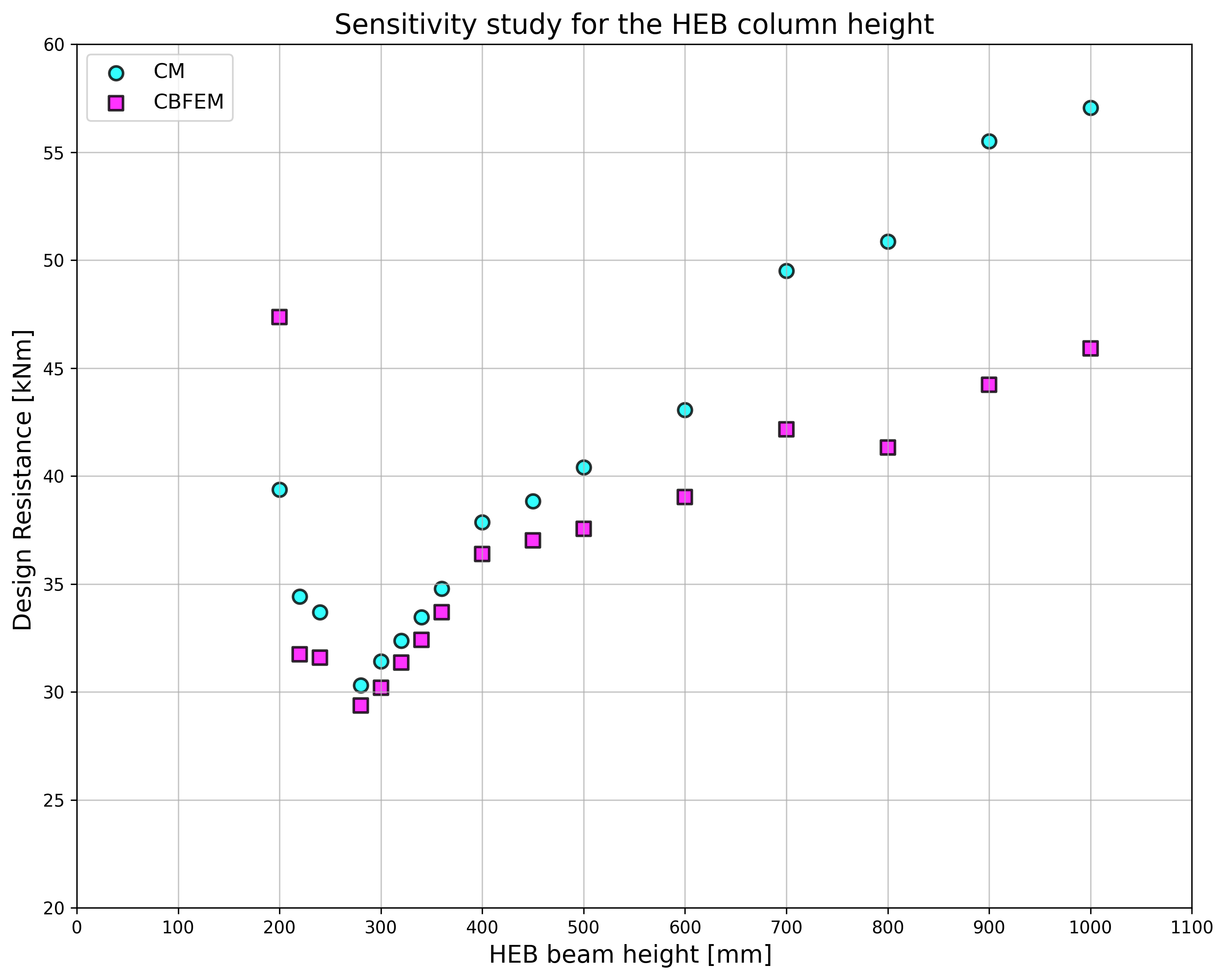
承载力验证 针对不同柱截面开展了节点承载力敏感性研究。节点几何尺寸见图 5.3.1。表 5.3.1 和图 5.3.3 汇总了端板 P18 相对于柱截面尺寸逐步扩大时的计算结果。
表 5.3.1 不同椽条下端板弱轴节点承载力预测结果
Fig. 5.3.3 Comparison resistance of end plate minor axis connection predicted by CBFEM and CM \textsf{\textit{\footnotesize{Fig. 5.3.3 Comparison resistance of end plate minor axis connection predicted by CBFEM and CM}}} Fig. 5.3.3 Comparison resistance of end plate minor axis connection predicted by CBFEM and CM
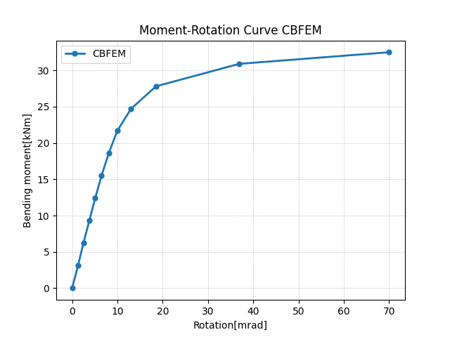
整体行为 整体行为通过力-变形曲线表示。IPE 240 梁通过六颗 M16 8.8 螺栓与 HEB 300 柱相连。端板几何尺寸见图 5.3.1 和表 5.3.1。两种方法的结果对比见图 5.3.4 和表 5.3.2。两种方法预测的设计承载力相近。与组件法相比,CBFEM(基于组件的有限元模型)通常给出较低的初始刚度。
Fig. 5.3.4 Prediction of behavior of end plate minor axis connection on moment rotational curve CBFEM \textsf{\textit{\footnotesize{Fig. 5.3.4 Prediction of behavior of end plate minor axis connection on moment rotational curve CBFEM}}} Fig. 5.3.4 Prediction of behavior of end plate minor axis connection on moment rotational curve CBFEM
表 5.3.2 整体行为主要特征参数
CM CBFEM CM/CBFEM 初始刚度 [kNm/rad] 16130 2232 7.23 设计承载力 [kNm] 31 30 1,03
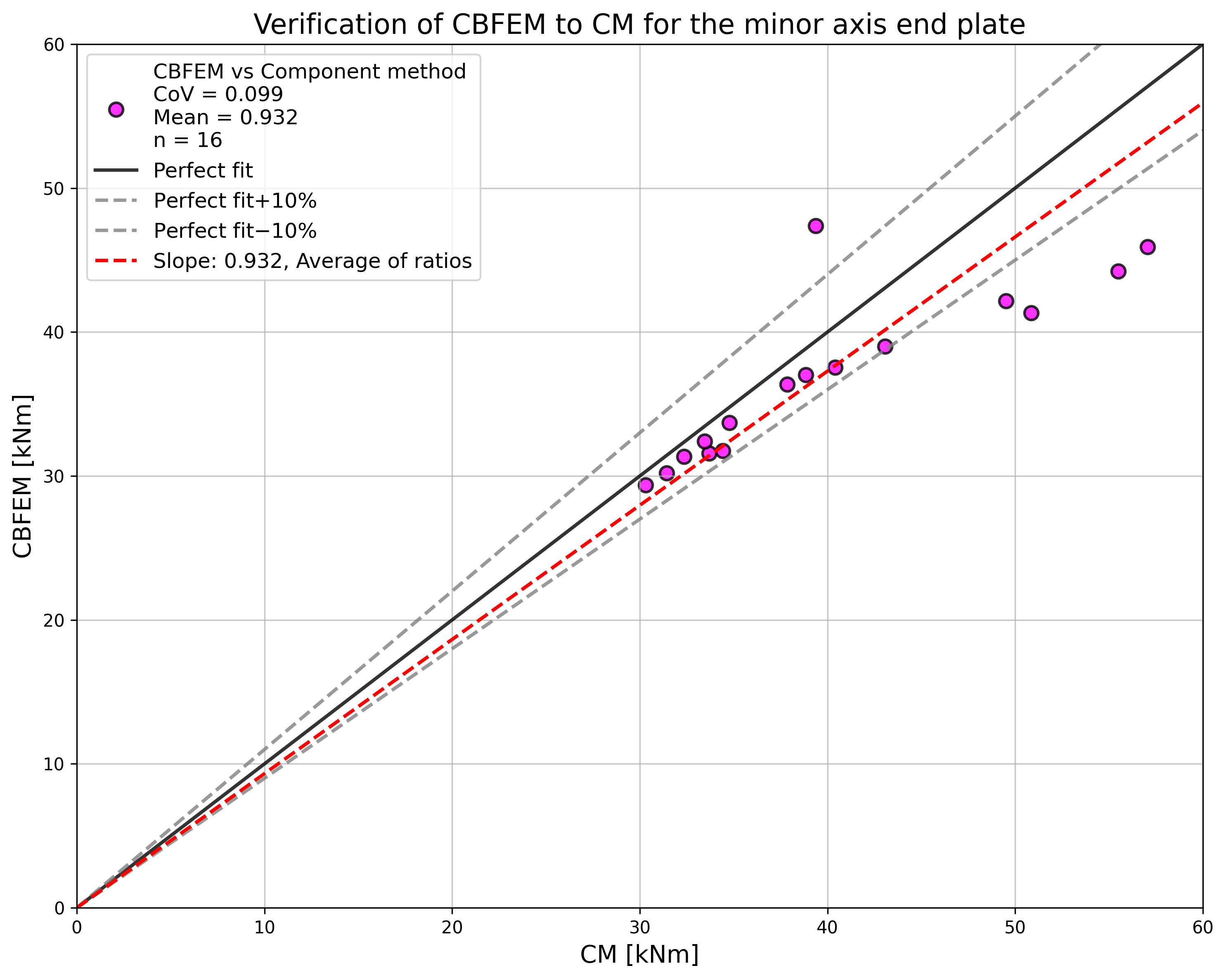
研究结果汇总于对比 CBFEM(基于组件的有限元模型)与组件法承载力的图表中;见图 5.3.5。结果表明,两种方法之间的差异最大为 14%。CBFEM(基于组件的有限元模型)在所有情况下预测的承载力均低于组件法,这是基于(Steenhuis 等,1998)中简化假设的结果。类似结论亦可见于(Wang 和 Wang,2012)的研究成果。
Fig. 5.3.5 Summary of verification of CBFEM to CM for the end plate minor axis connection \textsf{\textit{\footnotesize{Fig. 5.3.5 Summary of verification of CBFEM to CM for the end plate minor axis connection}}} Fig. 5.3.5 Summary of verification of CBFEM to CM for the end plate minor axis connection
基准算例 基准算例依据图 5.3.1 针对端板弱轴节点进行设置,修改后的几何参数汇总如下。
输入参数
钢材 S235
柱 HEB 300
梁 IPE 240
螺栓 6×M16 8.8
焊缝厚度 5 mm
端板厚度 t p = 18 mm
输出结果
抗弯设计承载力 M Rd = 30 kNm
控制组件——受弯柱腹板
参考文献 EN 1993-1-5, Eurocode 3, Design of steel structures – Part 1-5: Plated Structural Elements , CEN, Brussels, 2005.
Steenhuis M., Jaspart J. P., Gomes F., Leino T. Application of the component method to steel joints, in Control of the Semi-rigid Behaviour of Civil Engineering Structural Connections Conference , COST C1, Liege, Belgium, 1998, 125-143.
Wang Z., Wang T. Experiment and finite element analysis for the end plate minor axis connection of semi-rigid steel frames, Tumu Gongcheng Xuebao/China Civil Engineering Journal , 45 (8), 2012, 83-89.