描述 本文以焊接檐口弯矩节点为例,介绍转动刚度的预测方法。研究了开口截面柱 HEB 与梁 IPE 的焊接节点,并通过弯矩-转角图描述节点行为。将组件法(CM)解析模型的计算结果与CBFEM(基于组件的有限元模型)数值结果进行对比,并提供了基准算例。
解析模型 节点的转动刚度应根据各基本组件的变形确定,各组件由刚度系数 k i 表示。节点转动刚度 S j 由下式求得:
S j = E z 2 μ Σ i 1 k i S_j = \frac{E z^2}{\mu \Sigma_i \frac{1}{k_i}} S j = μ Σ i k i 1 E z 2
其中:
ki 为节点组件 i 的刚度系数;
z 为力臂;见第 6.2.7 条;
μ 为刚度比;见第 6.3.1 条。
本算例中考虑的节点组件为:受剪柱腹板面板 k 1 、受压柱腹板 k 2, 以及受拉柱腹板 k 3 。刚度系数定义见 EN 1993-1-8:2005 表 6.11。初始刚度 S j,ini 在弯矩 M j,Ed ≤ 2/3 Mj ,Rd 时求得。
S j = E z 2 1 k 1 + 1 k 2 + 1 k 3 S_j = \frac{E \, z^{2}}{\frac{1}{k_1} + \frac{1}{k_2} + \frac{1}{k_3}} S j = k 1 1 + k 2 1 + k 3 1 E z 2
S j , ini = S j 1.5 ψ S_{j,\text{ini}} = \frac{S_j}{1.5^{\psi}} S j , ini = 1. 5 ψ S j
其中
S j S_{j} S j
ψ \psi ψ
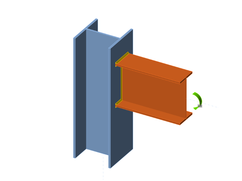
本算例中,开口截面梁 IPE 400 与柱 HEB 300 焊接连接。梁翼缘通过焊喉厚度为 9 mm 的焊缝与柱翼缘相连,梁腹板通过焊喉厚度为 5 mm 的焊缝连接。焊缝采用塑性应力分布。梁和柱的材料均为 S235。设计承载力由受剪柱面板和横向受压柱面板两个组件控制。基本组件的刚度系数计算值、初始刚度、设计承载力对应刚度及梁的转角汇总于表 10.1.1。
Tab. 10.1.1 Results of the analytical model \textsf{\textit{\footnotesize{Tab. 10.1.1 Results of the analytical model}}} Tab. 10.1.1 Results of the analytical model
数值模型 关于CBFEM(基于组件的有限元模型)刚度预测的详细信息,请参见第 3.9 章。对同一檐口弯矩节点进行建模,结果汇总于表 10.1.2。设计承载力由受拉柱腹板组件 5% 塑性应变控制。CBFEM 分析可计算任意加载阶段的转动刚度。
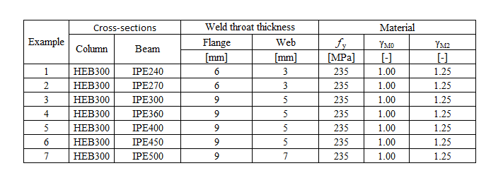
试验概述 为便于对比,柱截面设定为 HEB300,梁截面为变量。所有材料均采用 S235。
Tab. 10.1.2 Experimental overview \textsf{\textit{\footnotesize{Tab. 10.1.2 Experimental overview}}} Tab. 10.1.2 Experimental overview
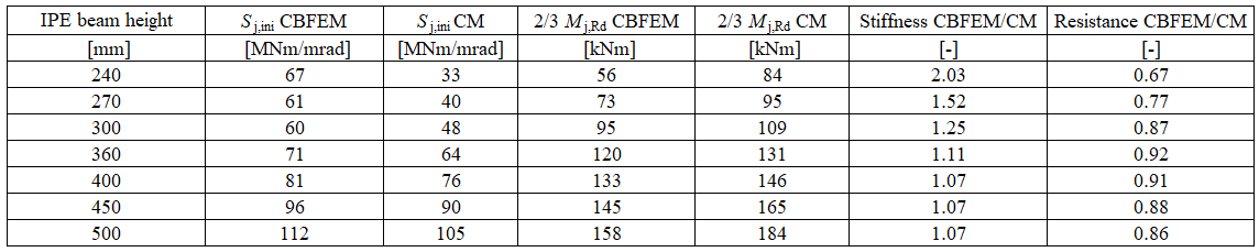
Tab. 10.1.3 Experimental overview \textsf{\textit{\footnotesize{Tab. 10.1.3 Experimental overview}}} Tab. 10.1.3 Experimental overview
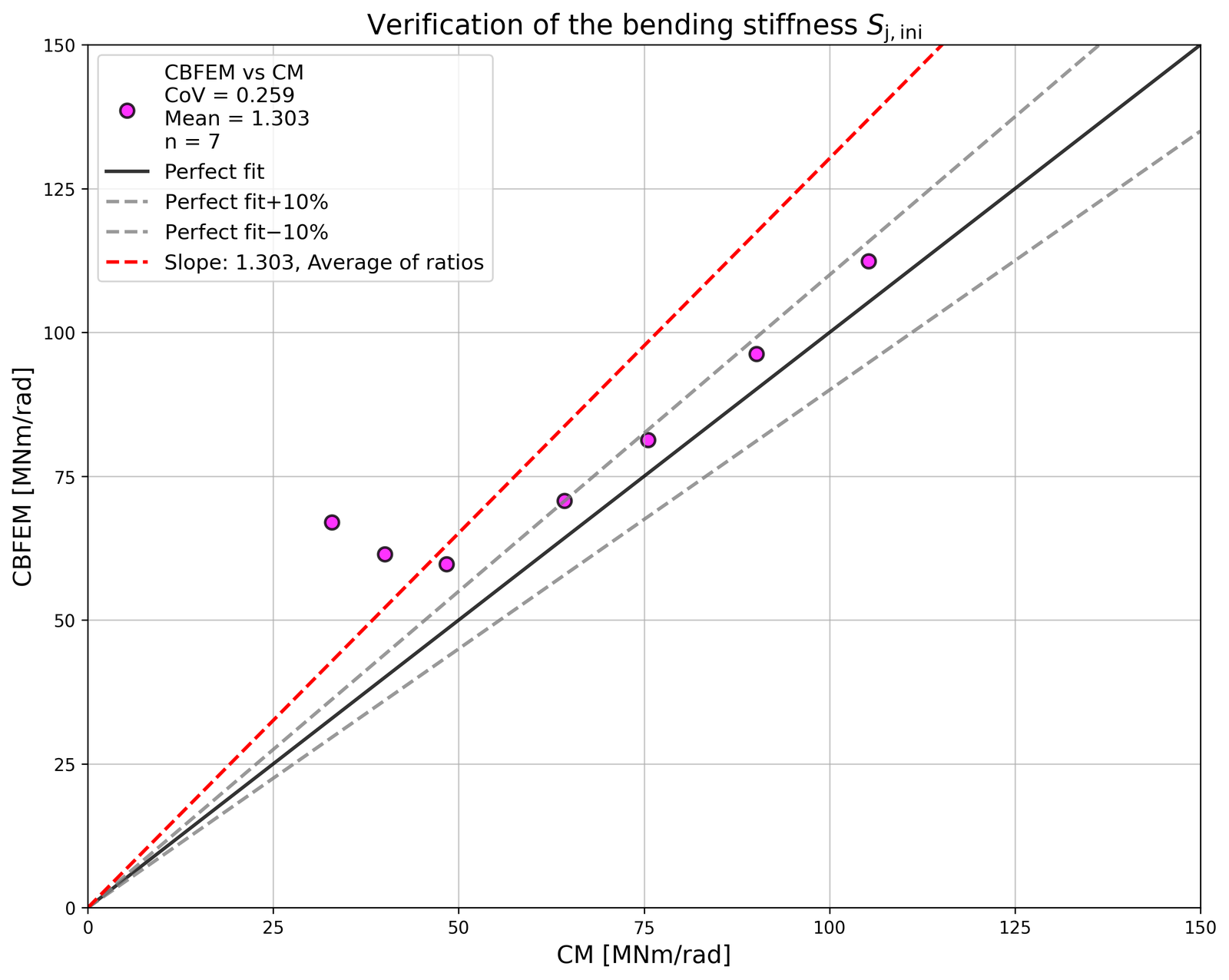
Fig. 1 Verification of CBFEM to CM \textsf{\textit{\footnotesize{Fig. 1 Verification of CBFEM to CM}}} Fig. 1 Verification of CBFEM to CM
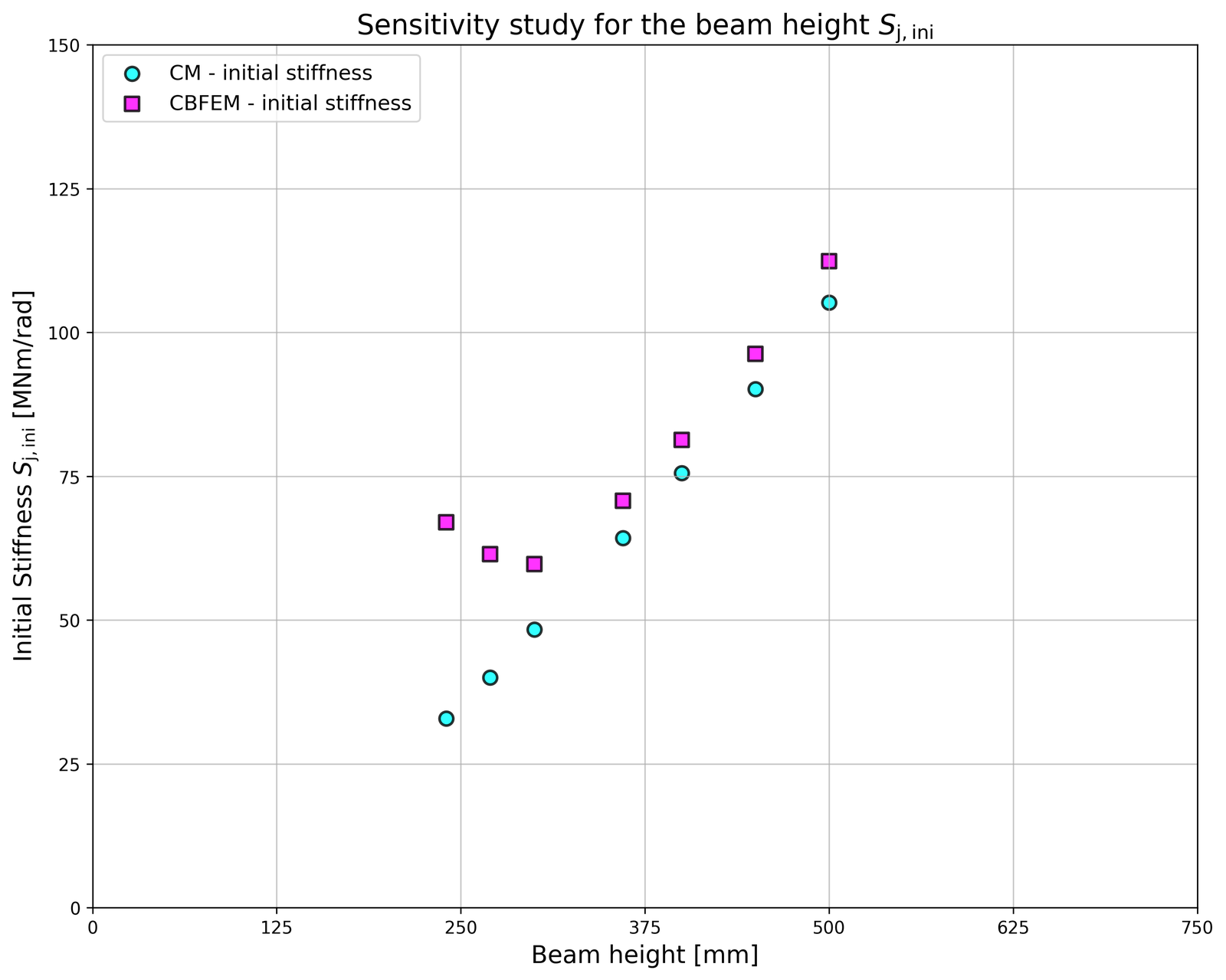
Fig. 2Sensitivity study of beam IPE cross-section \textsf{\textit{\footnotesize{Fig. 2Sensitivity study of beam IPE cross-section}}} Fig. 2Sensitivity study of beam IPE cross-section
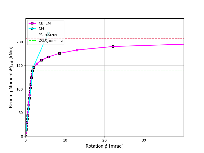
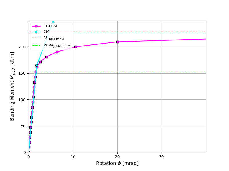
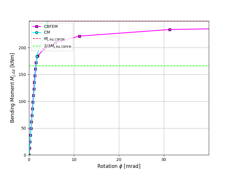
刚度验证 将CBFEM(基于组件的有限元模型)计算的转动刚度与 CM 进行对比。对比结果表明,初始刚度吻合良好,节点行为具有良好的对应性。CBFEM 与 CM 计算的刚度汇总于表 10.1.3。
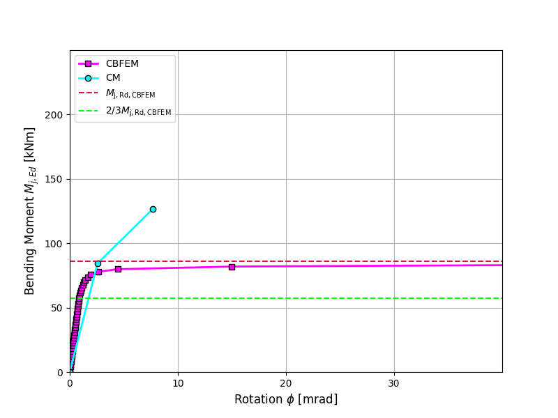
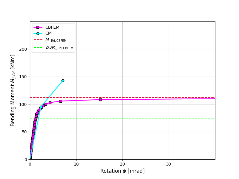
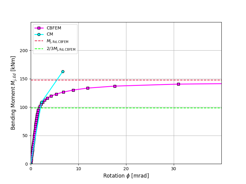
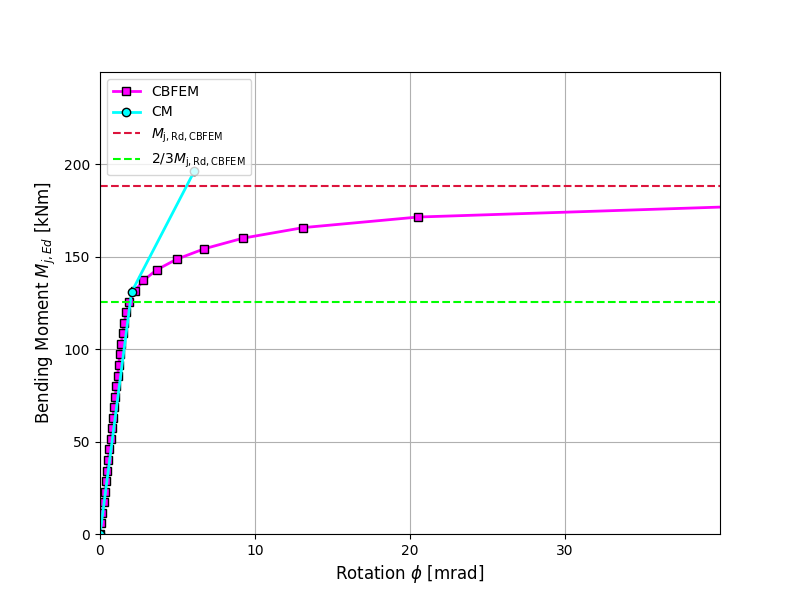
本文对焊接檐口弯矩节点的整体行为进行了对比,以弯矩-转角图加以描述。对节点进行分析,并计算被连接梁的刚度。主要特征量为在 2/3M j,Rd 处计算的初始刚度,其中 M j,Rd 为节点的设计弯矩承载力。弯矩-转角图如图 10.1.1 所示。
Fig. 3 Moment-rotation diagram for a welded eaves moment joint, IPE240 \textsf{\textit{\footnotesize{Fig. 3 Moment-rotation diagram for a welded eaves moment joint, IPE240}}} Fig. 3 Moment-rotation diagram for a welded eaves moment joint, IPE240
Fig. 4 Moment-rotation diagram for a welded eaves moment joint, IPE270 \textsf{\textit{\footnotesize{Fig. 4 Moment-rotation diagram for a welded eaves moment joint, IPE270}}} Fig. 4 Moment-rotation diagram for a welded eaves moment joint, IPE270
Fig. 5 Moment-rotation diagram for a welded eaves moment joint, IPE300 \textsf{\textit{\footnotesize{Fig. 5 Moment-rotation diagram for a welded eaves moment joint, IPE300}}} Fig. 5 Moment-rotation diagram for a welded eaves moment joint, IPE300
Fig. 6 Moment-rotation diagram for a welded eaves moment joint, IPE360 \textsf{\textit{\footnotesize{Fig. 6 Moment-rotation diagram for a welded eaves moment joint, IPE360}}} Fig. 6 Moment-rotation diagram for a welded eaves moment joint, IPE360
Fig. 7 Moment-rotation diagram for a welded eaves moment joint, IPE400 \textsf{\textit{\footnotesize{Fig. 7 Moment-rotation diagram for a welded eaves moment joint, IPE400}}} Fig. 7 Moment-rotation diagram for a welded eaves moment joint, IPE400
Fig. 8 Moment-rotation diagram for a welded eaves moment joint, IPE450 \textsf{\textit{\footnotesize{Fig. 8 Moment-rotation diagram for a welded eaves moment joint, IPE450}}} Fig. 8 Moment-rotation diagram for a welded eaves moment joint, IPE450
Fig. 9 Moment-rotation diagram for a welded eaves moment joint, IPE500 \textsf{\textit{\footnotesize{Fig. 9 Moment-rotation diagram for a welded eaves moment joint, IPE500}}} Fig. 9 Moment-rotation diagram for a welded eaves moment joint, IPE500
基准算例 输入参数 梁与柱
钢材 S235
柱 HEB 300
梁 IPE 400
翼缘焊缝焊喉厚度 a f = 9 mm
腹板焊缝焊喉厚度 a w = 5 mm
柱偏心距 s = 150 mm
双面角焊缝
输出结果
设计承载力
M j , R d = 199 k N m M_\mathrm{j,Rd}= 199 \quad \mathrm{kNm} M j , Rd = 199 kNm 荷载
M j , E d = 2 / 3 M j , R d = 133 k N m M_\mathrm{j,Ed}=2/3M_\mathrm{j,Rd}= 133\quad \mathrm{kNm} M j , Ed = 2/3 M j , Rd = 133 kNm 割线转动刚度
S j , i n i = 81.3 M N m / r a d S_\mathrm{j,ini}= 81.3\quad \mathrm{MNm/rad} S j , ini = 81.3 MNm/rad Fig. 10 Benchmark case for welded eaves moment joint (IPE 400 to HEB 300) \textsf{\textit{\footnotesize{Fig. 10 Benchmark case for welded eaves moment joint (IPE 400 to HEB 300)}}} Fig. 10 Benchmark case for welded eaves moment joint (IPE 400 to HEB 300)