บทนำ
เมื่อเครื่องมือคำนวณมีความสะดวกในการเข้าถึงและใช้งานมากขึ้น แม้แต่สำหรับวิศวกรที่มีประสบการณ์น้อย ความจำเป็นในการประเมินผลการวิเคราะห์เชิงคำนวณอย่างมีวิจารณญาณก็เพิ่มขึ้นตามไปด้วย ในสาขาการออกแบบโครงสร้างเหล็ก การวิเคราะห์ไฟไนต์เอลิเมนต์ (FEA) ของการเชื่อมต่อโครงสร้างถือเป็นก้าวที่กำลังพัฒนาอย่างรวดเร็ว อย่างไรก็ตาม ความน่าเชื่อถือของการวิเคราะห์ดังกล่าวสามารถสถาปนาได้ก็ต่อเมื่อผ่านกระบวนการตรวจสอบและยืนยันความถูกต้อง (V&V) อย่างเป็นระบบเท่านั้น หากปราศจาก V&V ที่เข้มงวด ผลลัพธ์จากไฟไนต์เอลิเมนต์ย่อมขาดความน่าเชื่อถือและไม่สามารถใช้เป็นพื้นฐานในการตัดสินใจทางวิศวกรรมได้
บทความนี้ทบทวนบทที่คัดเลือกจาก Component-Based Finite Element Design of Steel Connections โดย František Wald และคณะ โดยคำนวณใหม่ด้วย IDEA StatiCa เวอร์ชันล่าสุด นอกจากนี้ บางบทได้รับการขยายเพิ่มเติมด้วยตัวอย่างเสริม เพื่อเพิ่มความครอบคลุมและความแม่นยำของกระบวนการตรวจสอบ บทความนี้มุ่งเสริมสร้างรากฐานเชิงระเบียบวิธีของการออกแบบการเชื่อมต่อ และเป็นเอกสารอ้างอิงที่เชื่อถือได้สำหรับทั้งงานวิจัยเชิงวิชาการและการปฏิบัติงานวิศวกรรม
พื้นฐานทางทฤษฎี
คุณสามารถค้นหาคำอธิบายของวิธี CBFEM ได้จากเอกสารพื้นฐานทางทฤษฎีออนไลน์สองฉบับแยกกัน:
IDEA StatiCa Connection – การออกแบบโครงสร้างของการเชื่อมต่อโครงสร้างเหล็ก - บทนำทั่วไปเกี่ยวกับวิธี CBFEM และแบบจำลองการวิเคราะห์ภายในแอป Connection
การตรวจสอบองค์ประกอบการเชื่อมต่อโครงสร้างเหล็ก (EN) - คำอธิบายการนำ Eurocode (EN) ไปใช้สำหรับการตรวจสอบที่กำหนด
IDEA StatiCa Member – เสถียรภาพของชิ้นส่วน - บทนำทั่วไปเกี่ยวกับการวิเคราะห์เสถียรภาพ การโก่งเดาะ และการวิเคราะห์ไม่เชิงเส้นทางเรขาคณิตพร้อมความไม่สมบูรณ์ (GMNIA) ภายในแอป Member
การเชื่อมต่อโครงสร้างเหล็กแบบเชื่อม
คำอธิบาย
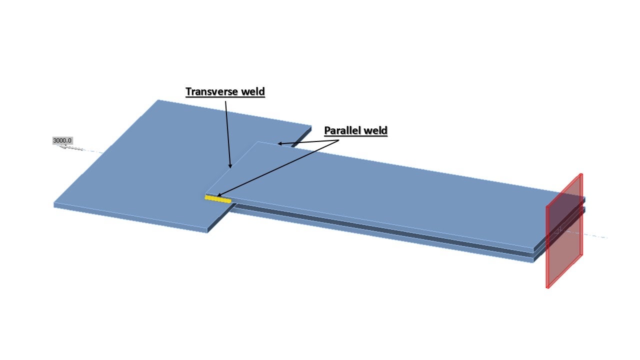
วัตถุประสงค์ของบทนี้คือการตรวจสอบวิธี Component-Based Finite Element (CBFEM) ของรอยเชื่อมฟิลเล็ตในการต่อทาบกับวิธีส่วนประกอบ (CM) แผ่นเหล็กสองแผ่นถูกเชื่อมต่อในสามรูปแบบ ได้แก่ รอยเชื่อมตามขวาง รอยเชื่อมตามยาว และการรวมกันของรอยเชื่อมตามขวางและตามยาว ความยาวและความหนาของคอรอยเชื่อมเป็นพารามิเตอร์ที่แปรผันในการศึกษา การศึกษานี้ยังครอบคลุมรอยเชื่อมยาวที่มีความต้านทานลดลงเนื่องจากการกระจุกตัวของความเค้น จุดต่อรับแรงปกติ
แบบจำลองเชิงวิเคราะห์
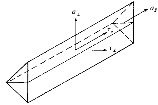
รอยเชื่อมฟิลเล็ตเป็นส่วนประกอบเดียวที่ตรวจสอบในการศึกษา รอยเชื่อมได้รับการออกแบบให้เป็นส่วนประกอบที่อ่อนแอที่สุดในจุดต่อ รอยเชื่อมได้รับการออกแบบตาม EN 1993-1-8:2005 ความต้านทานการออกแบบของรอยเชื่อมฟิลเล็ตถูกกำหนดโดยใช้วิธีทิศทาง (Directional method) ที่ระบุไว้ใน Cl. 4.5.3.2 ใน EN 1993-1-8:2005 วิธีการคำนวณที่ใช้ได้สำหรับการตรวจสอบความแข็งแรงของรอยเชื่อมฟิลเล็ตอยู่บนพื้นฐานของสมมติฐานที่ว่าความเค้นกระจายสม่ำเสมอภายในหน้าตัดคอของรอยเชื่อมฟิลเล็ต ซึ่งนำไปสู่ความเค้นปกติและความเค้นเฉือนดังแสดงในรูปที่ 4.1.1 ดังนี้:
- σ⊥ คือความเค้นปกติตั้งฉากกับหน้าตัดคอ
- σ∥ คือความเค้นปกติขนานกับแกนของรอยเชื่อมในหน้าตัด
- τ⊥ คือความเค้นเฉือน (ในระนาบของหน้าตัดคอ) ตั้งฉากกับแกนของรอยเชื่อม
- τ∥ คือความเค้นเฉือน (ในระนาบของหน้าตัดคอ) ขนานกับแกนของรอยเชื่อม
ความเค้นปกติ σ∥ ขนานกับแกนไม่ถูกพิจารณาเมื่อตรวจสอบความต้านทานการออกแบบของรอยเชื่อม
ความต้านทานการออกแบบของรอยเชื่อมฟิลเล็ตจะเพียงพอหากเงื่อนไขต่อไปนี้ทั้งสองข้อได้รับการตอบสนอง:
ในการต่อทาบที่ยาวกว่า ตัวประกอบลดค่า กำหนดโดย:
แต่
แบบจำลองเชิงตัวเลข
ส่วนประกอบรอยเชื่อมใน CBFEM อธิบายไว้ใน พื้นฐานทางทฤษฎีทั่วไป และ พื้นฐานทางทฤษฎีตาม EN วัสดุแบบ Nonlinear elastic-plastic ถูกใช้สำหรับรอยเชื่อมในการศึกษานี้ ความเครียดพลาสติกขีดจำกัดถูกบรรลุในส่วนที่ยาวกว่าของรอยเชื่อม และจุดสูงสุดของความเค้นถูกกระจายใหม่
การตรวจสอบความต้านทาน
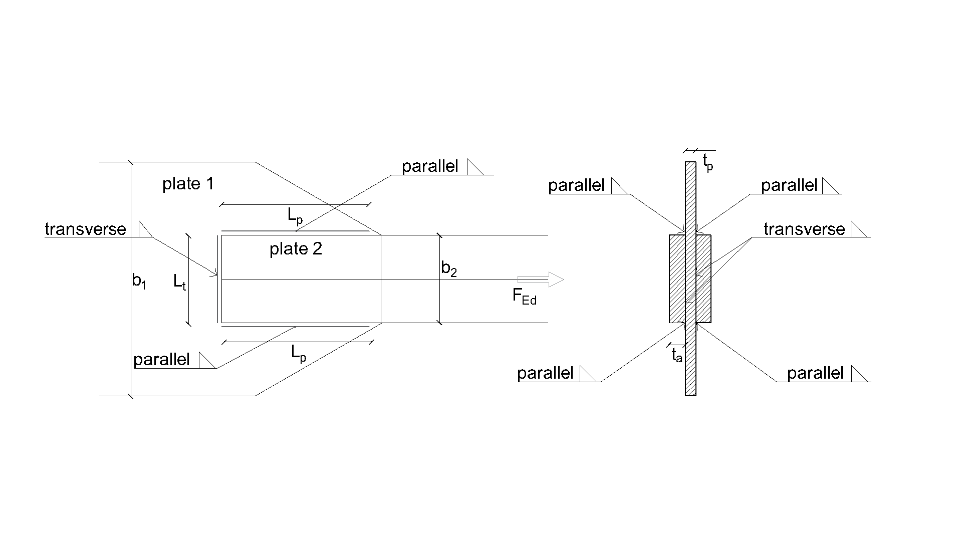
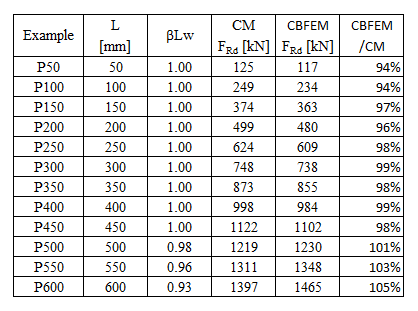
ภาพรวมของตัวอย่างที่พิจารณาและคุณสมบัติของวัสดุแสดงไว้ใน Tab. 4.1.1 รูปแบบรอยเชื่อมคือ T สำหรับรอยเชื่อมตามขวาง P สำหรับรอยเชื่อมขนาน และ TP สำหรับการรวมกันของทั้งสอง ดูรูปทรงเรขาคณิตในรูปที่ 4.1.2 เกรดเหล็กคือ S235 (fy = 235 MPa, fu = 360 MPa, E = 210 GPa, βw = 0,8) ตัวประกอบความปลอดภัยบางส่วนคือ γM0 = 1.0, γM2 = 1.25 รูปทรงเรขาคณิตของแบบจำลองแสดงในรูปที่ 4.1.2 แผ่นเหล็กมีความหนา 20 มม. การเชื่อมต่อมีความสมมาตร และแผ่นเหล็กถูกดึงออกจากการต่อเชื่อมแบบทาบ ความยาวและความกว้างของแผ่นเหล็กถูกปรับตามความยาวของรอยเชื่อมขนานและตามขวาง ความต้านทานของรอยเชื่อมเป็นรูปแบบการวิบัติที่ควบคุมเสมอ ความหนาของคอรอยเชื่อมคือ 3 มม. ความยาวของรอยเชื่อมตามขวางและขนานแปรผันในการศึกษาเชิงพารามิเตอร์นี้
ความต้านทานการออกแบบรอยเชื่อมที่คำนวณโดย CBFEM ถูกเปรียบเทียบกับผลลัพธ์ของ CM ผลลัพธ์แสดงไว้ใน Tab. 4.1.1 – 4.1.3 และรูปที่ 4.1.3 – 4.1.5
การคำนวณความต้านทานของรอยเชื่อมตามขวาง
โดยที่:
- ความหนาของคอรอยเชื่อม
- แรงปกติที่กระทำต่อชิ้นส่วน
- ความยาวรวมของรอยเชื่อมตามขวาง
- ตัวประกอบสหสัมพันธ์ที่นำมาจาก EN 1993-1-8 Table 4.1
- ความแข็งแรงดึงประลัยระบุของชิ้นส่วนที่อ่อนแอกว่าที่เชื่อมต่อ
- ตัวประกอบความปลอดภัยบางส่วนสำหรับรอยเชื่อม
การคำนวณความต้านทานของรอยเชื่อมขนาน
โดยที่:
- ความหนาของคอรอยเชื่อม
- แรงเฉือนที่กระทำต่อชิ้นส่วน
- ความยาวรวมของรอยเชื่อมขนาน
- ตัวประกอบสหสัมพันธ์ที่นำมาจาก EN 1993-1-8 Table 4.1
- ตัวประกอบลดค่าสำหรับรอยเชื่อมยาว EN 1993-1-8 Equation 4.9
- ความแข็งแรงดึงประลัยระบุของชิ้นส่วนที่อ่อนแอกว่าที่เชื่อมต่อ
- ตัวประกอบความปลอดภัยบางส่วนสำหรับรอยเชื่อม
การคำนวณรอยเชื่อมตามขวางและขนาน
ความต้านทานที่คำนวณด้วยมือสำหรับการรวมกันของรอยเชื่อมตามขวางและขนานคือผลรวมของความต้านทานตามขวางและขนานที่ได้จากสมการข้างต้น
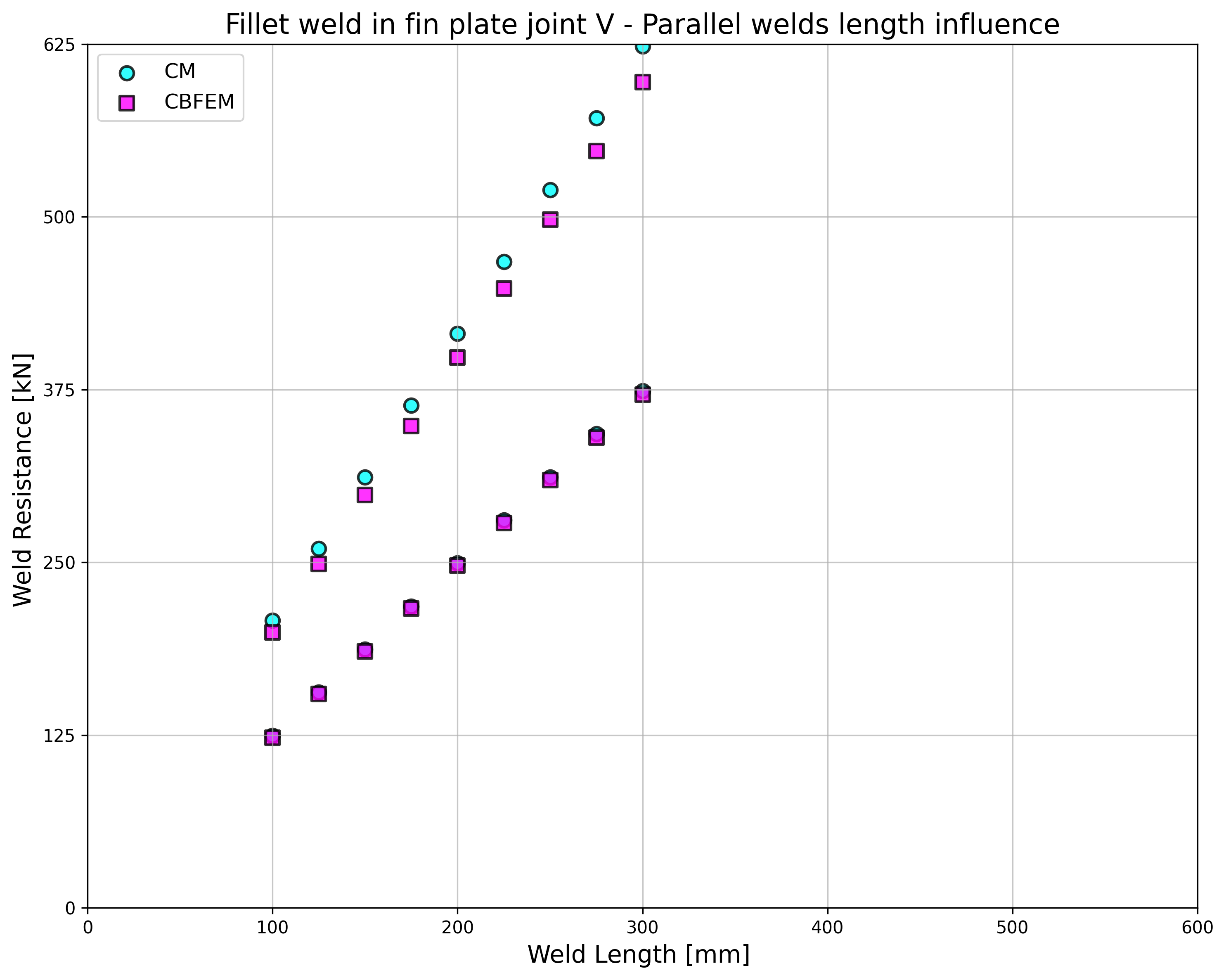
การนำเสนอผลลัพธ์
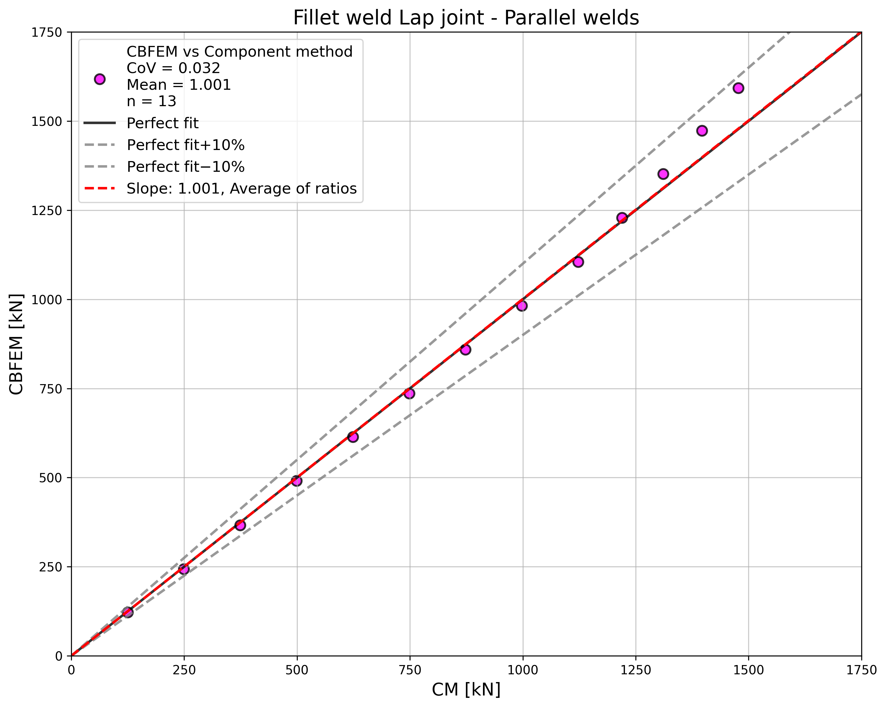
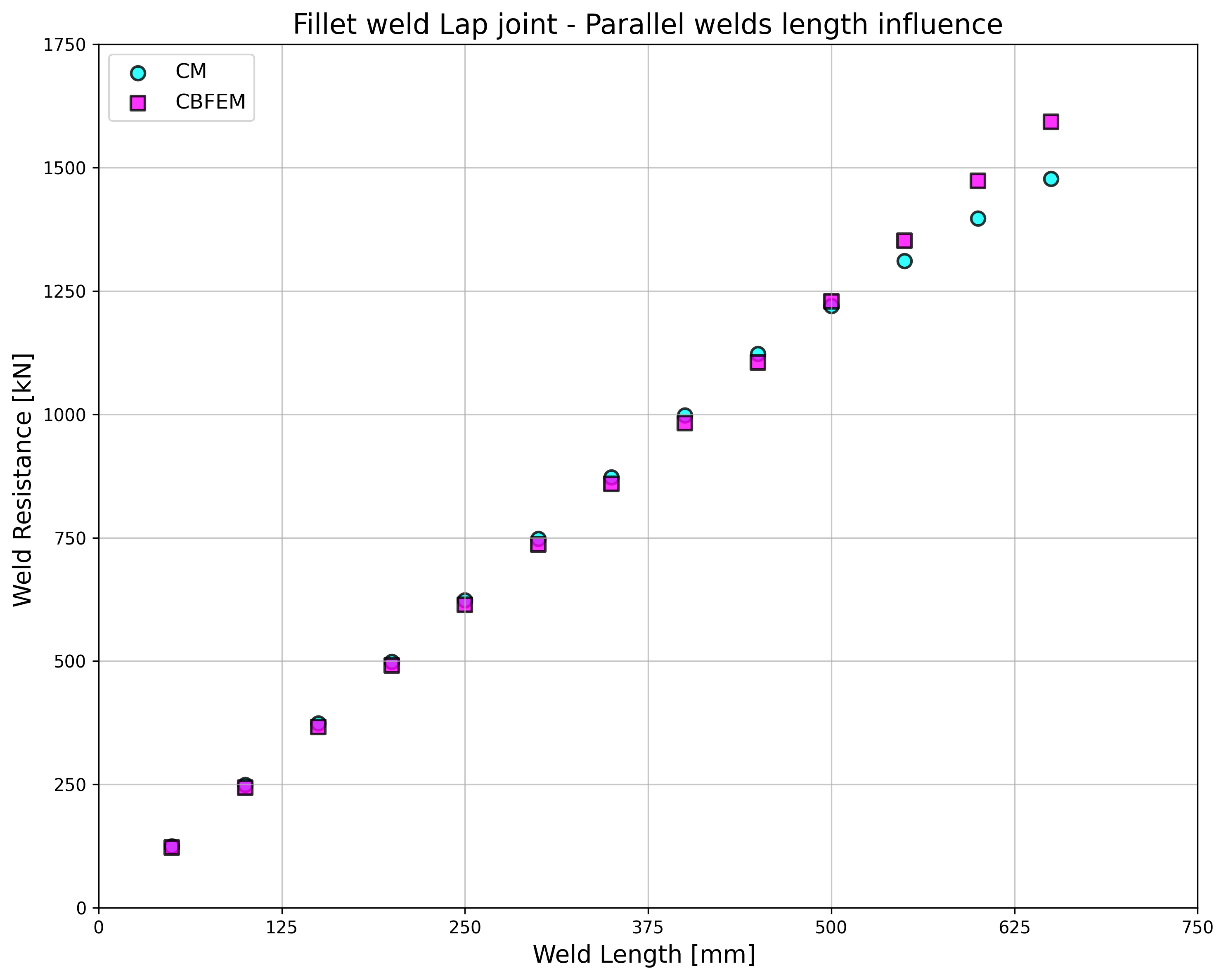
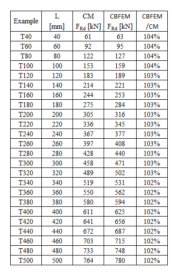
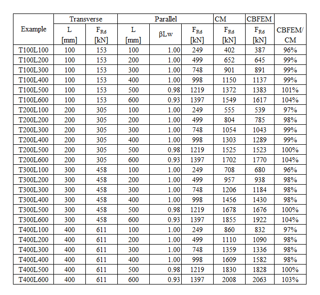
ความต้านทานของรอยเชื่อมขนาน รอยเชื่อมตามขวาง และกลุ่มรอยเชื่อมหลายทิศทางมีค่าใกล้เคียงกันตาม CM และ CBFEM ความแตกต่างที่มากที่สุดในการศึกษานี้คือ 6% ในความต้านทานแรง
ผลลัพธ์ CBFEM ของรอยเชื่อมขนานมีความอนุรักษ์นิยมเล็กน้อย แต่เริ่มแตกต่างกันสำหรับรอยเชื่อมยาว การลดลงของความต้านทานเนื่องจากรอยเชื่อมยาวไม่ได้ถูกจับโดย CBFEM แต่ไม่คาดว่ารอยเชื่อมที่ยาวกว่า 200 เท่าของความหนาคอจะปรากฏในการเชื่อมต่อใดๆ และจนถึงความยาวนี้ผลลัพธ์ยังคงใกล้เคียงกันมาก
สำหรับรอยเชื่อมตามขวาง CBFEM ให้ผลลัพธ์ที่สอดคล้องกันมากโดยมีความต้านทานสูงกว่า 2–4%
ตัวอย่าง Benchmark
ข้อมูลนำเข้า
ชิ้นส่วนที่ 1 – Iw60x500
• เชื่อมจากแผ่นเหล็กที่มีความหนา t = 20 มม.
• ความกว้าง b = 500 มม.
• เอาส่วนเอวออกโดยการดำเนินการผลิตแบบ Opening
• เหล็ก S235
ชิ้นส่วนที่ 2 – แผ่นเหล็ก 20x1000
• ความหนา t = 20 มม.
• ความกว้าง b = 1000 มม.
• เหล็ก S235
• ระยะออฟเซ็ต ex = –90 มม.
รอยเชื่อมฟิลเล็ตตามขวางที่ทั้งสองด้านของชิ้นส่วนที่ 2
• ความหนาของคอ a = 3 มม.
• ความยาวรอยเชื่อม Lt = 100 มม.
รอยเชื่อมฟิลเล็ตขนานที่ทั้งสองด้านของชิ้นส่วนที่ 2
• ความหนาของคอ a = 3 มม.
• ความยาวรอยเชื่อม Lp = 100 มม.
ผลลัพธ์
• ความต้านทานการออกแบบในแรงดึง FRd = 387 kN (ควรสังเกตว่าความต้านทานถูกคำนวณโดยใช้ฟังก์ชัน "Stop at limit strain" ดังนั้นความต้านทาน CBFEM จริงอาจสูงกว่าเล็กน้อย)
คำอธิบาย
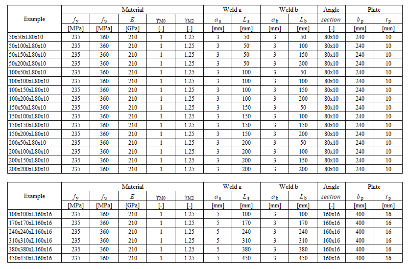
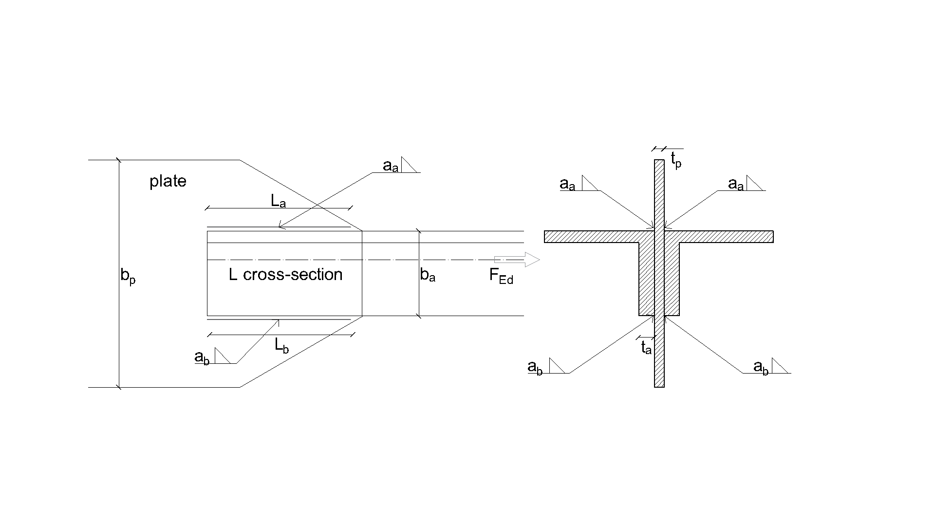
ในบทนี้ แบบจำลองรอยเชื่อมมุมในจุดต่อแผ่นเหล็กมุมที่คำนวณด้วยวิธี Component-Based Finite Element (CBFEM) ได้รับการตรวจสอบเทียบกับวิธี Component Method (CM) โดยเหล็กฉากถูกเชื่อมติดกับแผ่นเหล็กและรับแรงในแนวตั้งฉาก การศึกษาความไวจะพิจารณาขนาดของเหล็กฉากและความยาวของรอยเชื่อม
แบบจำลองเชิงวิเคราะห์
รอยเชื่อมมุมเป็นองค์ประกอบเดียวที่ศึกษาในการวิเคราะห์นี้ รอยเชื่อมได้รับการออกแบบตามบทที่ 4 ใน EN 1993-1-8:2005 ให้เป็นองค์ประกอบที่อ่อนแอที่สุดในจุดต่อ ความต้านทานการออกแบบของรอยเชื่อมมุมอธิบายไว้ใน หัวข้อ 4.1 ภาพรวมของตัวอย่างและวัสดุที่พิจารณาแสดงไว้ในตาราง 4.2.1 รูปทรงเรขาคณิตของจุดต่อพร้อมขนาดแสดงไว้ในรูปที่ 4.2.1
การคำนวณด้วยวิธี Component Method
การคำนวณด้วยมือนี้ละเว้นโมเมนต์เพิ่มเติมของรอยเชื่อม ซึ่งเกิดขึ้นจากการกระจายแรงไปยังส่วนหน้าตัด L ตาม EN 1993-1-8 (4.13)
ความต้านทานรวมคำนวณจากผลรวมของความต้านทานรอยเชื่อมด้านบนและด้านล่าง
โดยที่:
- ความหนาคอรอยเชื่อม
- แรงเฉือนที่กระทำต่อคาน
- ความยาวรอยเชื่อมขนาน
- ตัวประกอบสหสัมพันธ์ที่นำมาจากตาราง 4.1 ของ EN 1993-1-8
- ตัวประกอบลดสำหรับรอยเชื่อมยาว สมการ 4.9 ของ EN 1993-1-8
- กำลังดึงประลัยที่ระบุของชิ้นส่วนที่อ่อนแอกว่าที่เชื่อมต่อกัน
- ตัวประกอบความปลอดภัยบางส่วนสำหรับรอยเชื่อม
แบบจำลองเชิงตัวเลข
องค์ประกอบรอยเชื่อมใน CBFEM อธิบายไว้ใน พื้นฐานทางทฤษฎีทั่วไป และ พื้นฐานทางทฤษฎีตาม EN แบบจำลองรอยเชื่อมมีไดอะแกรมวัสดุแบบ elastic-plastic และจุดสูงสุดของความเค้นจะถูกกระจายตลอดความยาวรอยเชื่อม
การตรวจสอบความต้านทาน
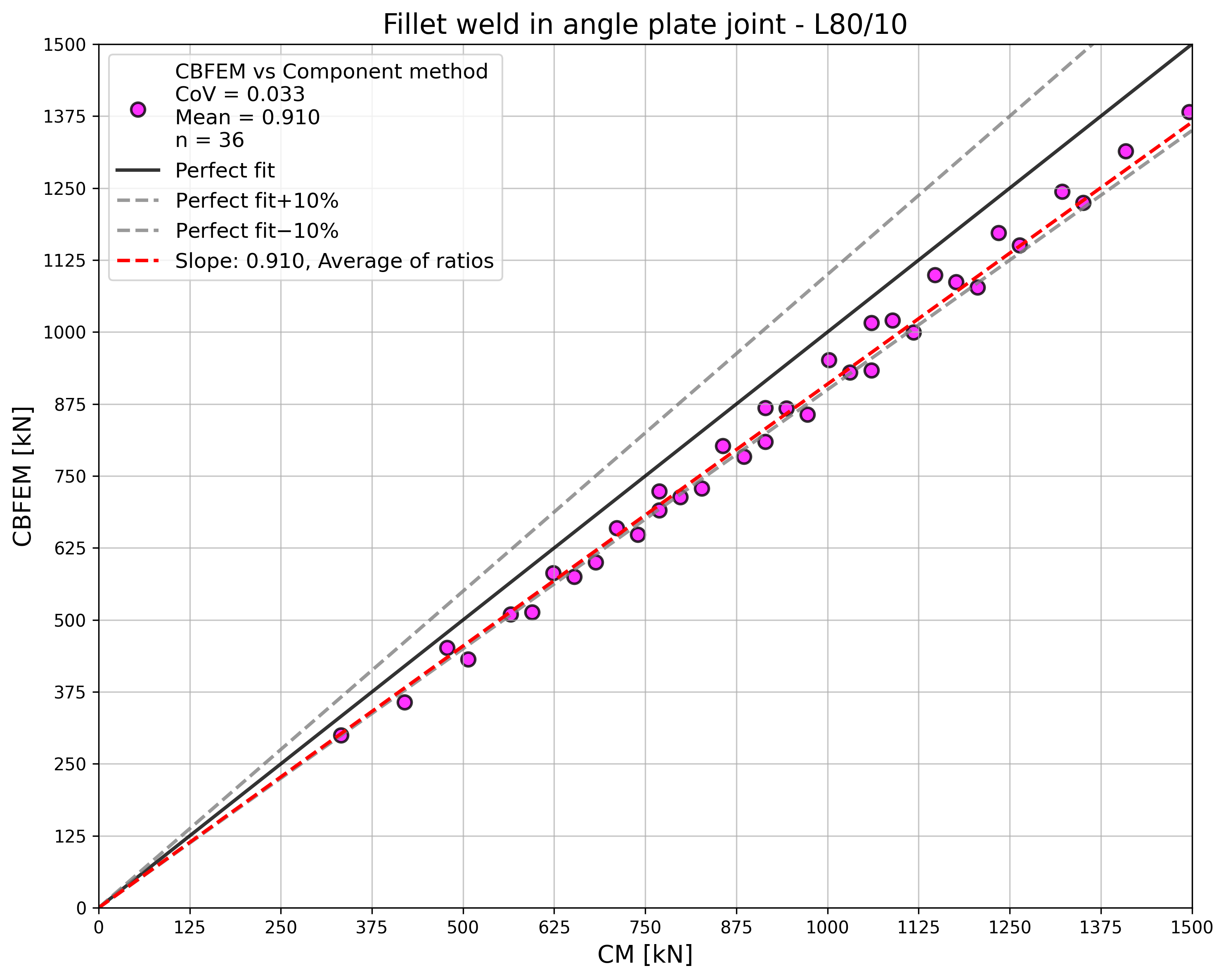
ค่าการออกแบบความต้านทานรอยเชื่อมที่คำนวณด้วย CBFEM ถูกเปรียบเทียบกับผลลัพธ์ของ CM ดูตาราง 4.2.2 พารามิเตอร์สองตัวที่ศึกษา ได้แก่ ความยาวของรอยเชื่อมและหน้าตัดเหล็กฉาก รูปที่ 4.2.2 แสดงการศึกษาความไวของความยาวรอยเชื่อมด้านล่าง ความยาวของรอยเชื่อมด้านบน a ในการศึกษาคือ La=100mm
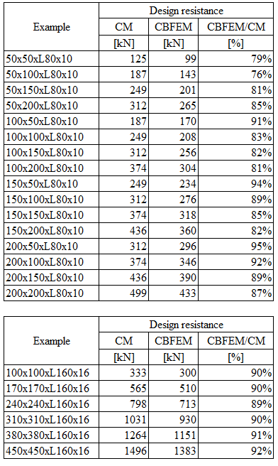
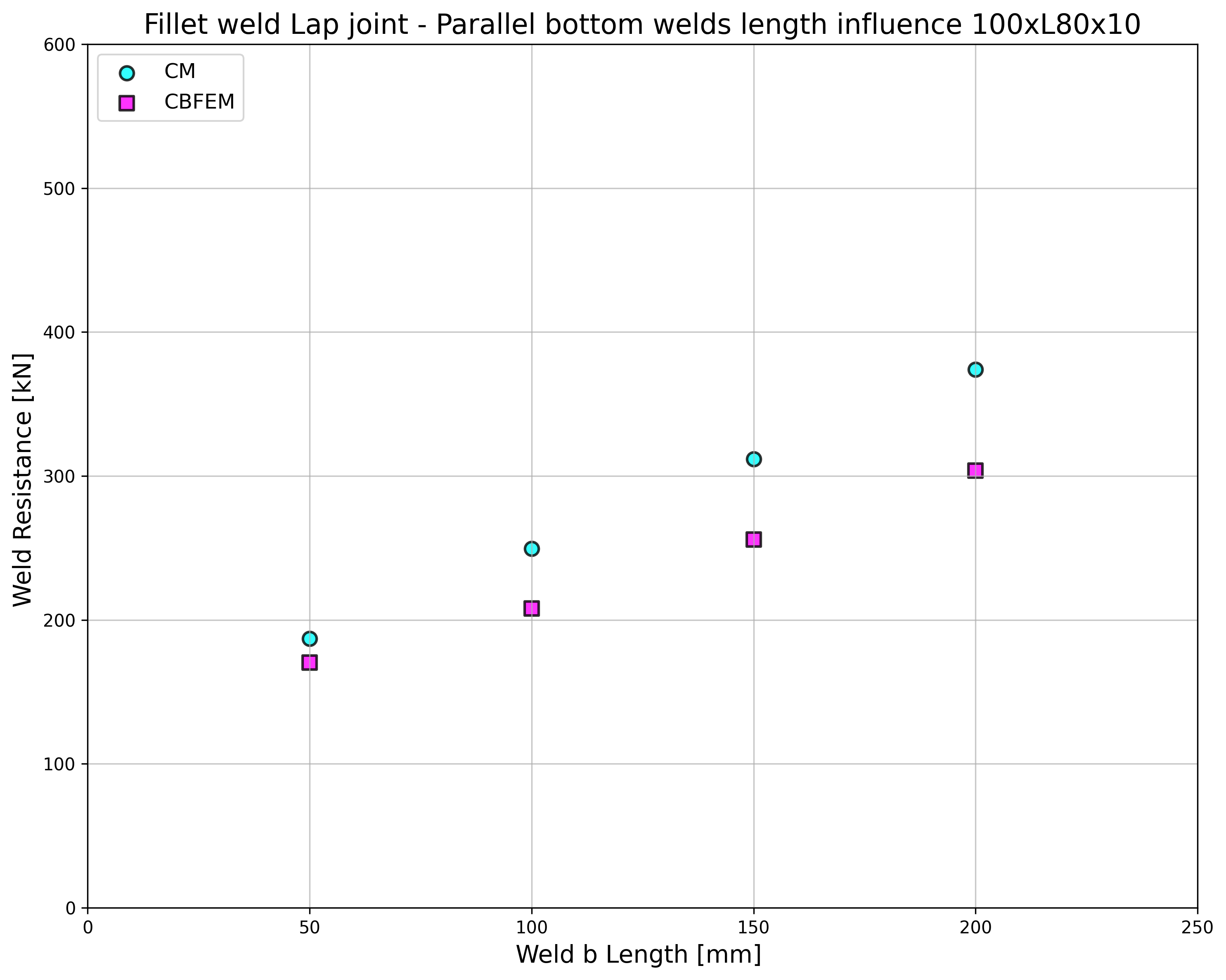
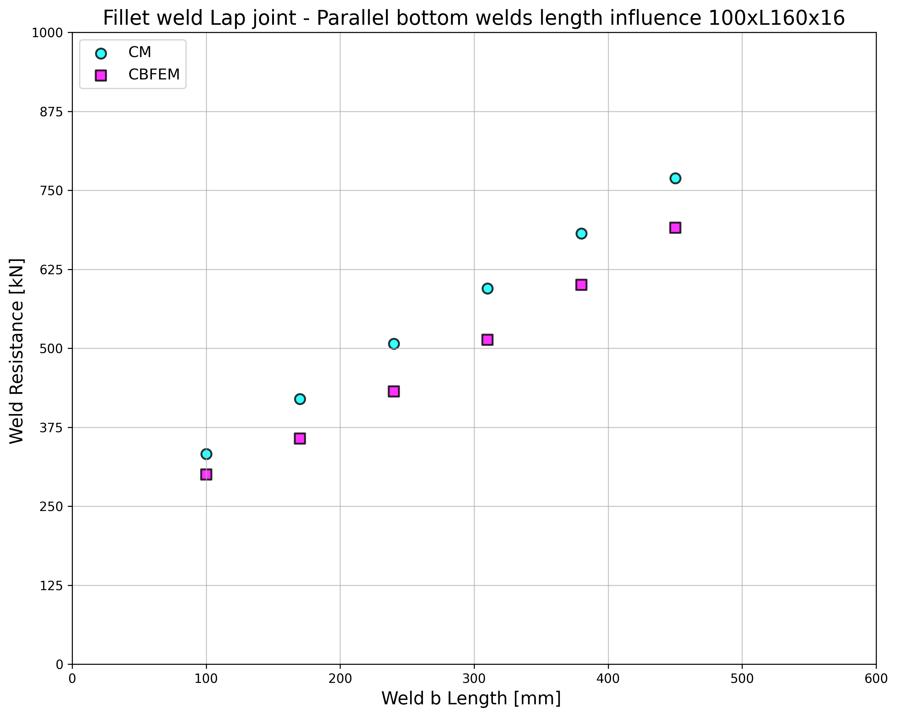
ผลลัพธ์ของ CBFEM และ CM ถูกเปรียบเทียบกัน และนำเสนอการศึกษาความไว อิทธิพลของความยาวรอยเชื่อมต่อค่าการออกแบบความต้านทานของจุดต่อเหล็กฉากเชื่อมแสดงในรูปที่ 4.2.2 การศึกษาแสดงให้เห็นความสอดคล้องที่ดีสำหรับทุกรูปแบบรอยเชื่อม เพื่อแสดงความแม่นยำของแบบจำลอง CBFEM ผลลัพธ์ของการศึกษาถูกสรุปในไดอะแกรมที่เปรียบเทียบค่าการออกแบบความต้านทานโดย CBFEM และ CM ดูรูปที่ 4.2.3 ผลลัพธ์แสดงให้เห็นว่าการทำนายทั้งหมดของ CBFEM อยู่ในด้านที่ปลอดภัยเมื่อเทียบกับ CM ซึ่งละเว้นความเยื้องศูนย์
ตัวอย่าง Benchmark
ข้อมูลนำเข้า
เหล็กฉาก
- หน้าตัด 2×L80×10
- ระยะห่างระหว่างเหล็กฉาก 16 มม.
แผ่นเหล็ก
- ความหนา tp = 16 มม.
- ความกว้าง bp = 240 มม.
รอยเชื่อม รอยเชื่อมมุมขนาน ดูรูปที่ 4.2.4
- ความหนาคอรอยเชื่อม aw = 3 มม.
- ความยาวรอยเชื่อมด้านบน Lw,top = 100 มม.
- ความยาวรอยเชื่อมด้านล่าง Lw,bottom = 50 มม.
ผลลัพธ์
- ค่าการออกแบบความต้านทานแรงดึง FRd = 170 kN (ควรสังเกตว่าความต้านทานนี้คำนวณโดยใช้ฟังก์ชัน "Stop at limit strain" ดังนั้นความต้านทาน CBFEM จริงอาจสูงกว่าเล็กน้อย)
คำอธิบาย
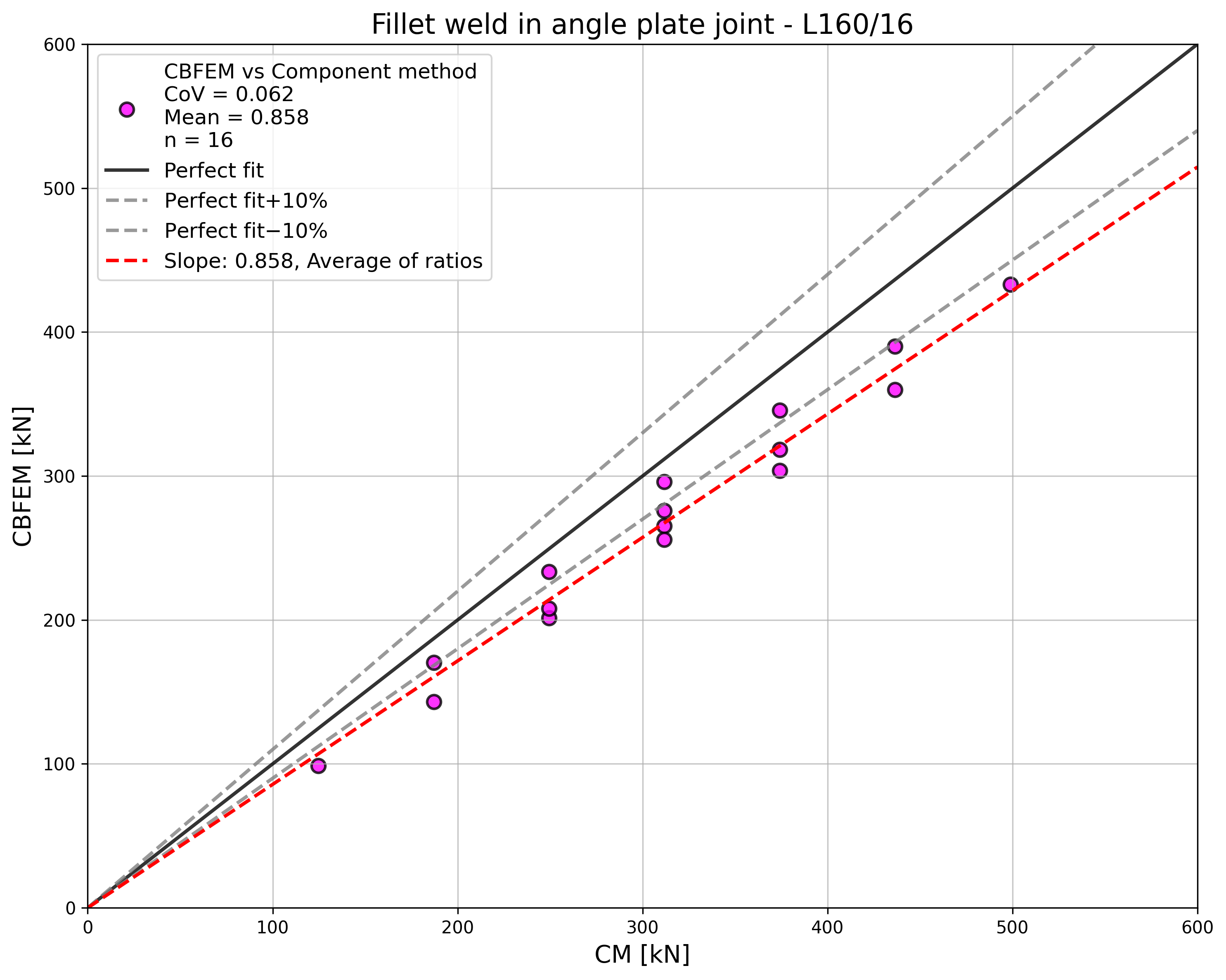
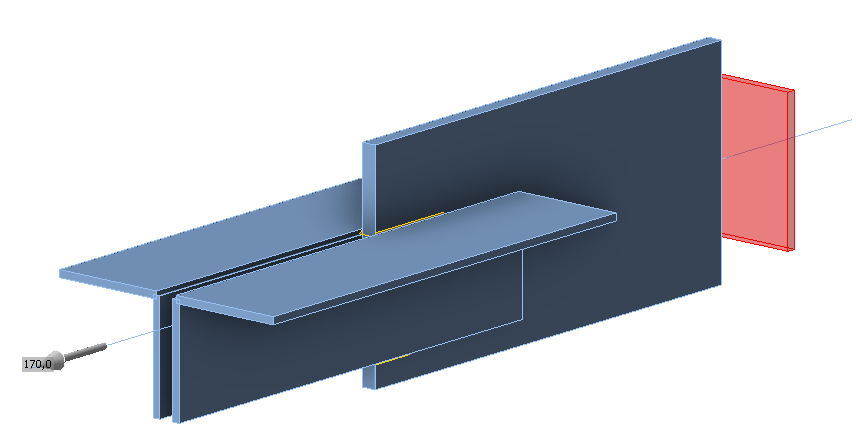
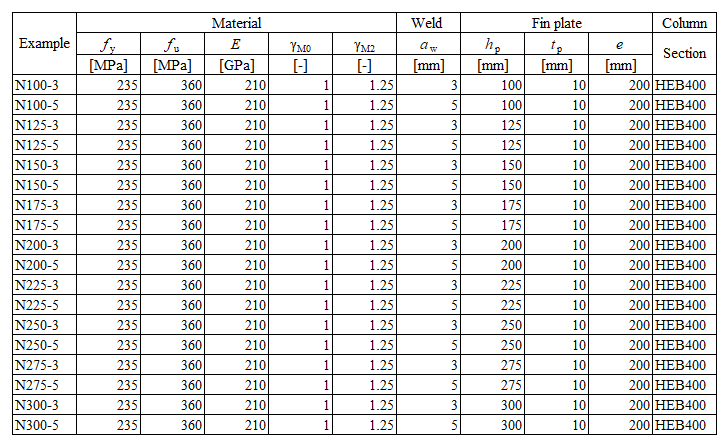
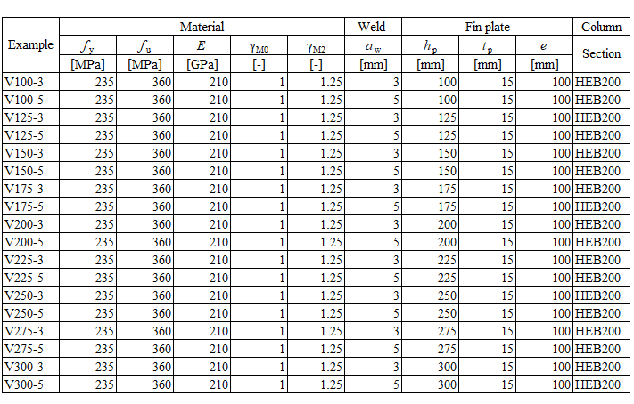
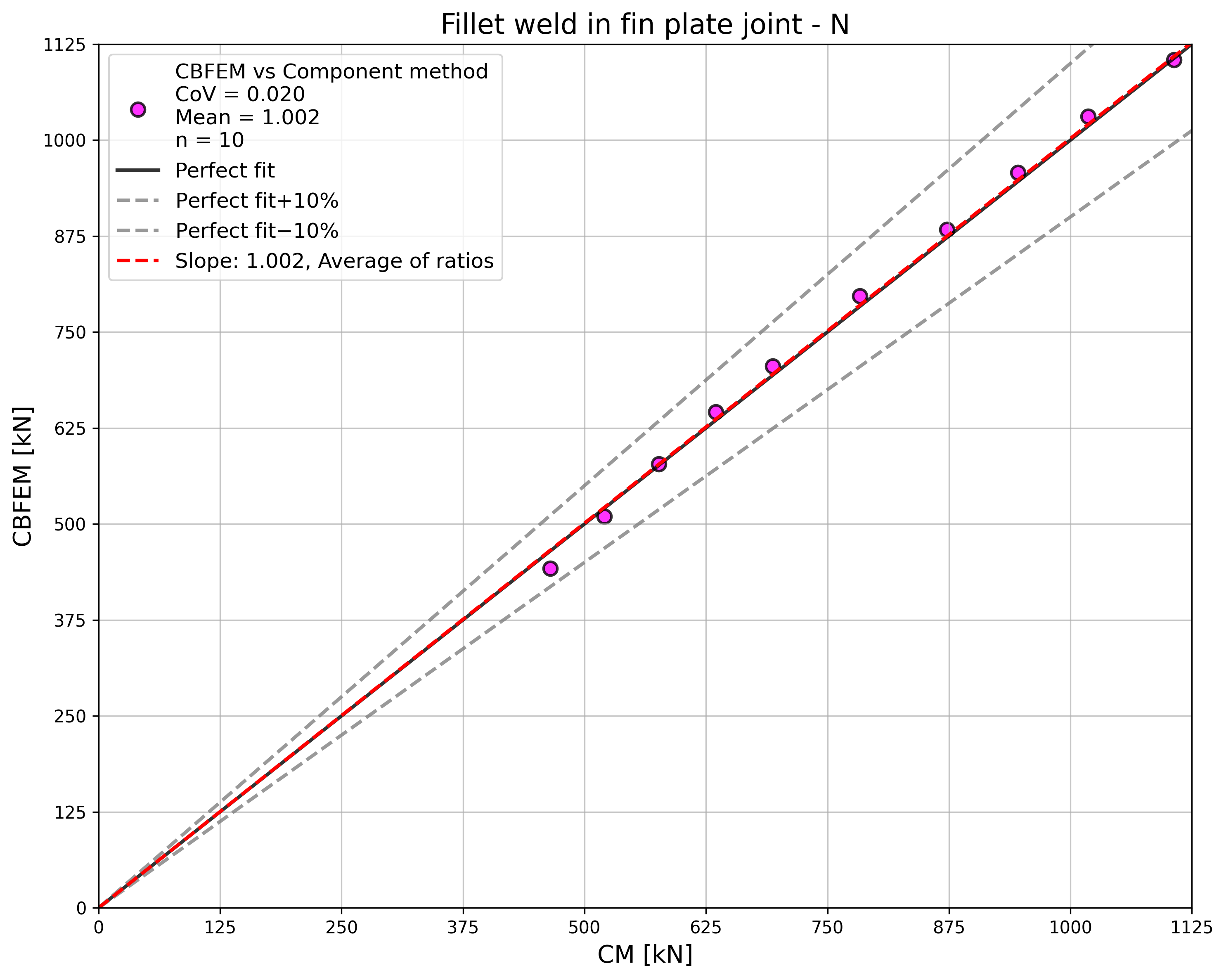
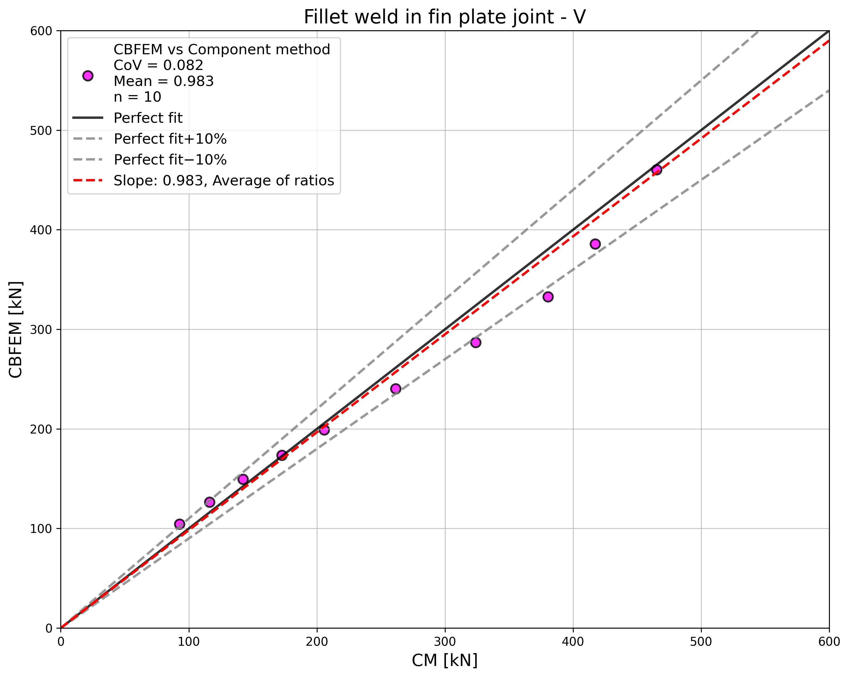
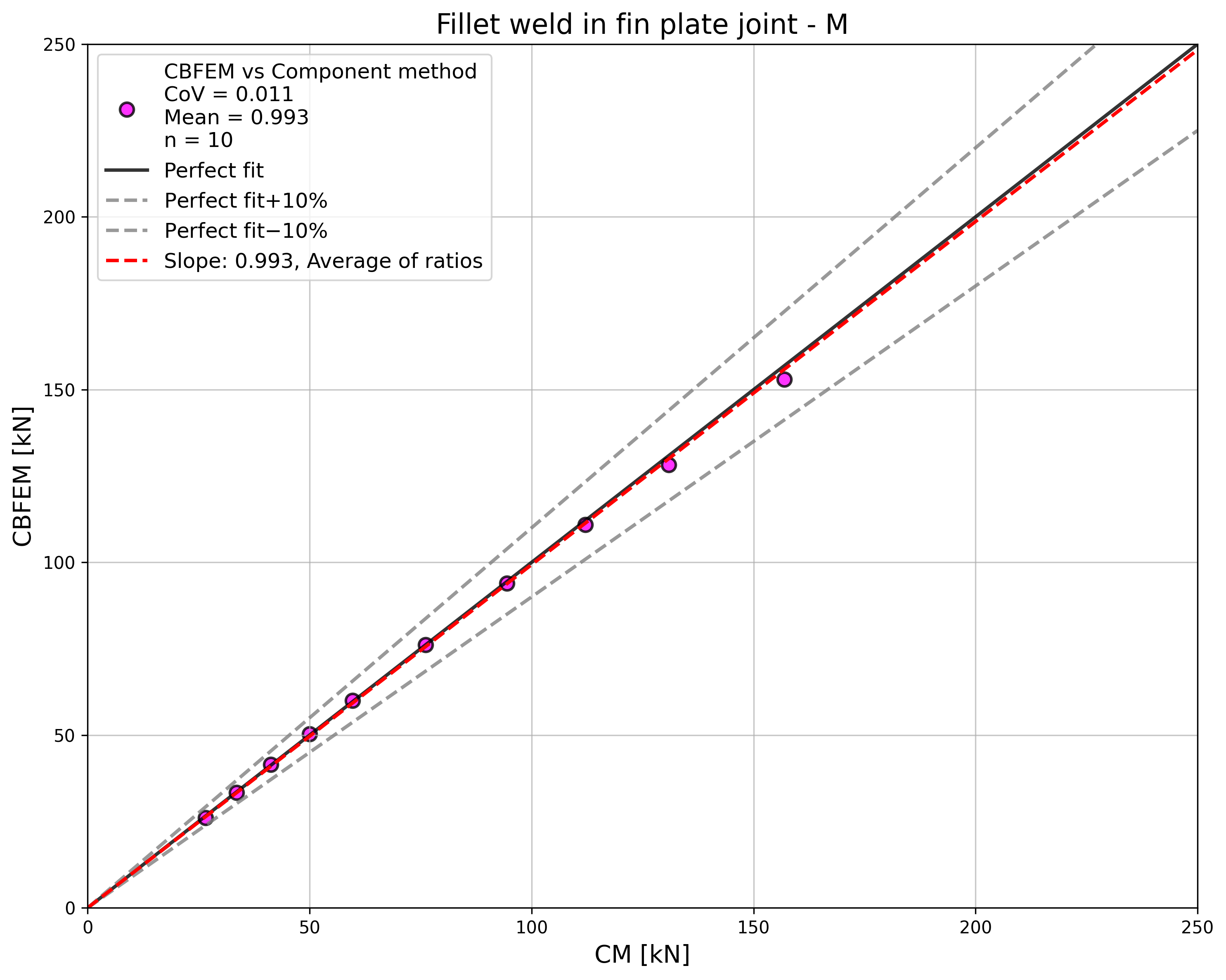
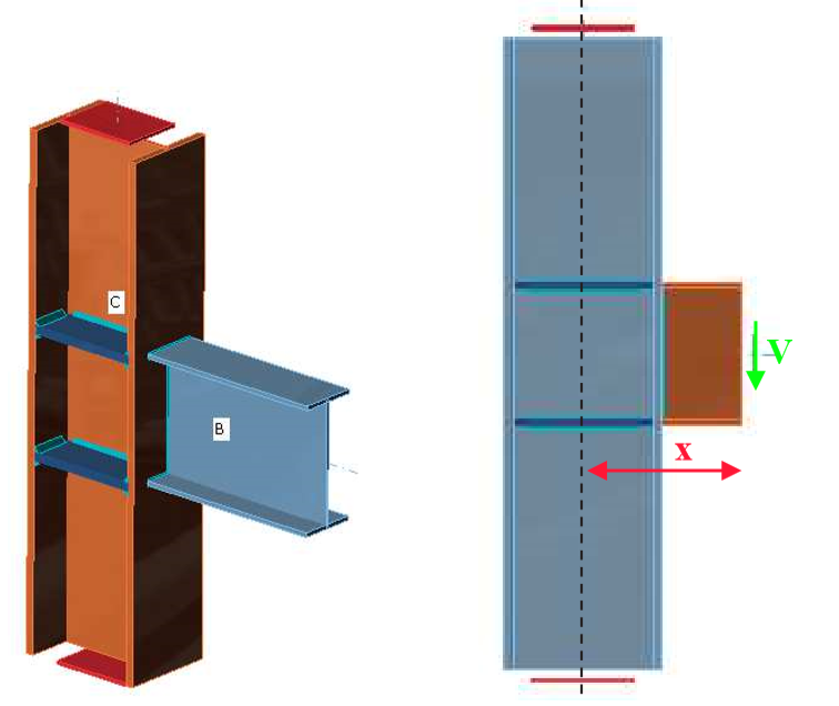
ในบทนี้ วิธี Component-Based Finite Element (CBFEM) ของรอยเชื่อมมุมในจุดต่อแผ่น Fin ได้รับการตรวจสอบกับวิธี Component Method (CM) แผ่น Fin ถูกเชื่อมกับเสาหน้าตัดเปิด HEB ความสูงของแผ่น Fin เปลี่ยนแปลงตั้งแต่ 150 ถึง 300 มม. แผ่น/รอยเชื่อมรับแรงตามแนวแกน แรงเฉือน และโมเมนต์ดัด
แบบจำลองเชิงวิเคราะห์
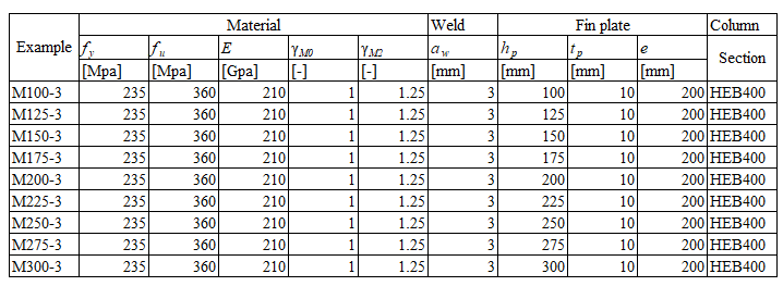
รอยเชื่อมมุมเป็นองค์ประกอบเดียวที่ศึกษาในงานนี้ รอยเชื่อมได้รับการออกแบบให้เป็นองค์ประกอบที่อ่อนแอที่สุดในจุดต่อตามบทที่ 4 ใน EN 1993-1-8:2005 ความต้านทานการออกแบบของรอยเชื่อมมุมอธิบายไว้ใน หัวข้อ 4.1 ภาพรวมของตัวอย่างและวัสดุที่พิจารณาแสดงไว้ในตาราง 4.3.1 มีการพิจารณากรณีแรงกระทำสามกรณี ได้แก่ แรงตามแนวแกน N แรงเฉือน V และโมเมนต์ดัด M รูปทรงเรขาคณิตของจุดต่อพร้อมขนาดแสดงในรูปที่ 4.3.1
การคำนวณความต้านทานแรงตามแนวแกนของรอยเชื่อม
โดยที่:
- ความหนาคอรอยเชื่อม
- แรงตามแนวแกนที่กระทำบนคาน
- ความยาวรอยเชื่อมรวม
- ตัวประกอบสหสัมพันธ์ที่นำมาจากตาราง 4.1 ของ EN 1993-1-8
- กำลังดึงประลัยที่ระบุของชิ้นส่วนที่อ่อนแอกว่าที่ต่อกัน
- ตัวประกอบความปลอดภัยบางส่วนสำหรับรอยเชื่อม
การคำนวณความต้านทานโมเมนต์ดัดของรอยเชื่อม
โดยที่:
- ความหนาคอรอยเชื่อม
- โมดูลัสหน้าตัดพลาสติกของรอยเชื่อม
- โมเมนต์ดัดที่กระทำบนคาน
- ความยาวรอยเชื่อมรวม
- ตัวประกอบสหสัมพันธ์ที่นำมาจากตาราง 4.1 ของ EN 1993-1-8
- กำลังดึงประลัยที่ระบุของชิ้นส่วนที่อ่อนแอกว่าที่ต่อกัน
- ตัวประกอบความปลอดภัยบางส่วนสำหรับรอยเชื่อม
การคำนวณความต้านทานแรงเฉือนของรอยเชื่อม
โดยที่:
- ความหนาคอรอยเชื่อม
- แรงเฉือนที่กระทำบนคาน
- ความยาวรอยเชื่อมรวม
- ตัวประกอบสหสัมพันธ์ที่นำมาจากตาราง 4.1 ของ EN 1993-1-8
- กำลังดึงประลัยที่ระบุของชิ้นส่วนที่อ่อนแอกว่าที่ต่อกัน
- ตัวประกอบความปลอดภัยบางส่วนสำหรับรอยเชื่อม
แบบจำลองเชิงตัวเลข
องค์ประกอบรอยเชื่อมใน CBFEM อธิบายไว้ใน พื้นฐานทางทฤษฎีทั่วไป และ พื้นฐานทางทฤษฎีตาม EN แบบจำลองรอยเชื่อมมีแผนภาพวัสดุแบบอิลาสติก-พลาสติก และความเค้นสูงสุดจะกระจายตลอดความยาวรอยเชื่อม
การตรวจสอบความต้านทาน
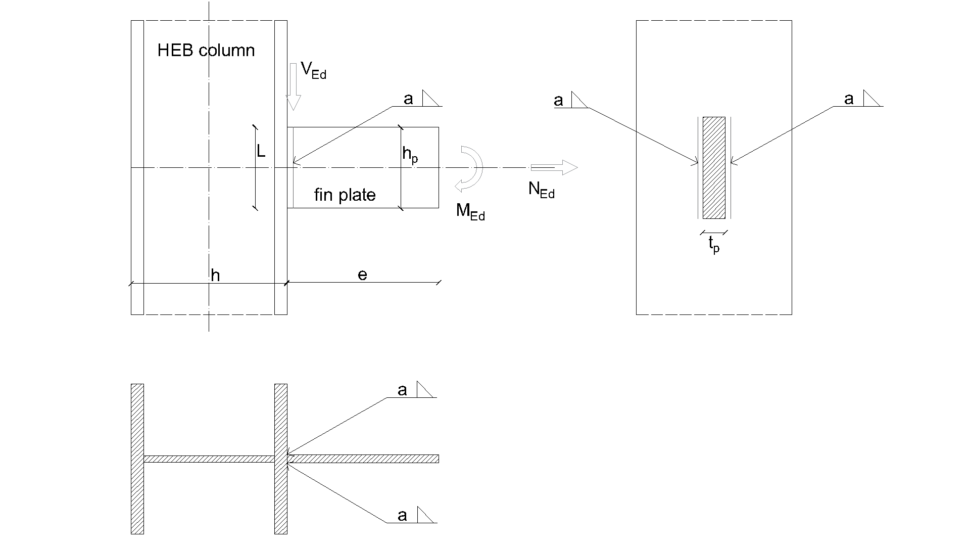
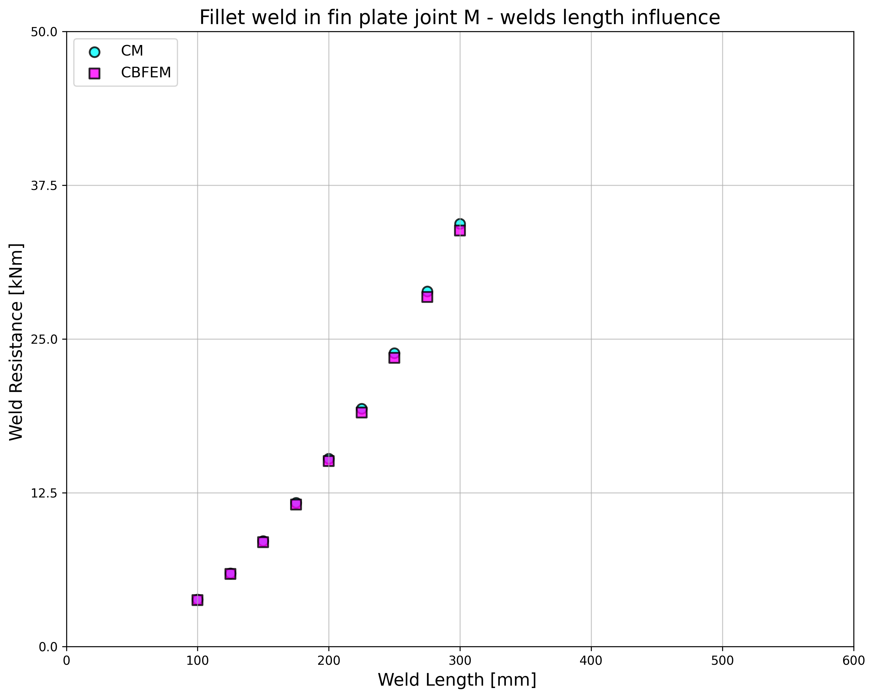
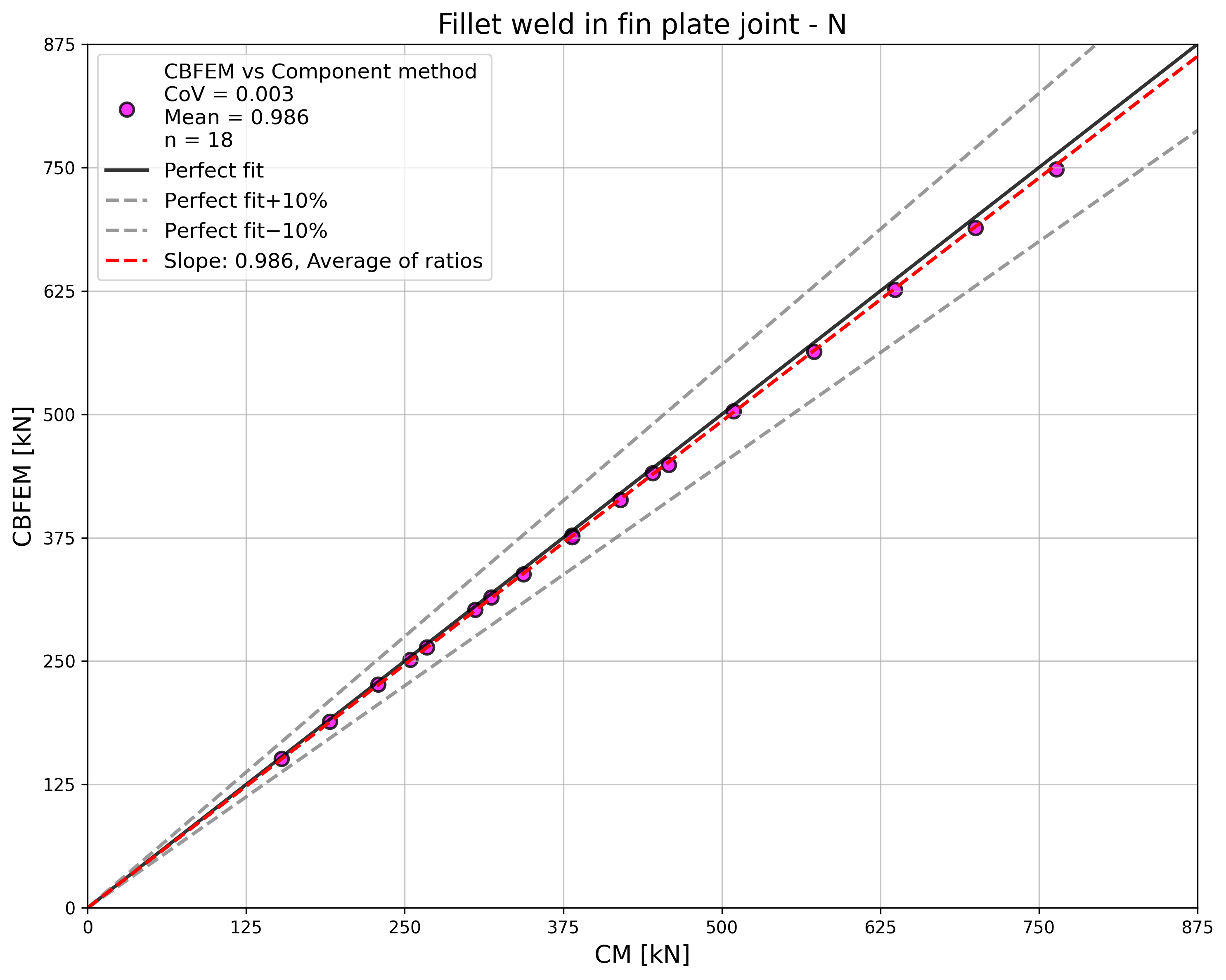
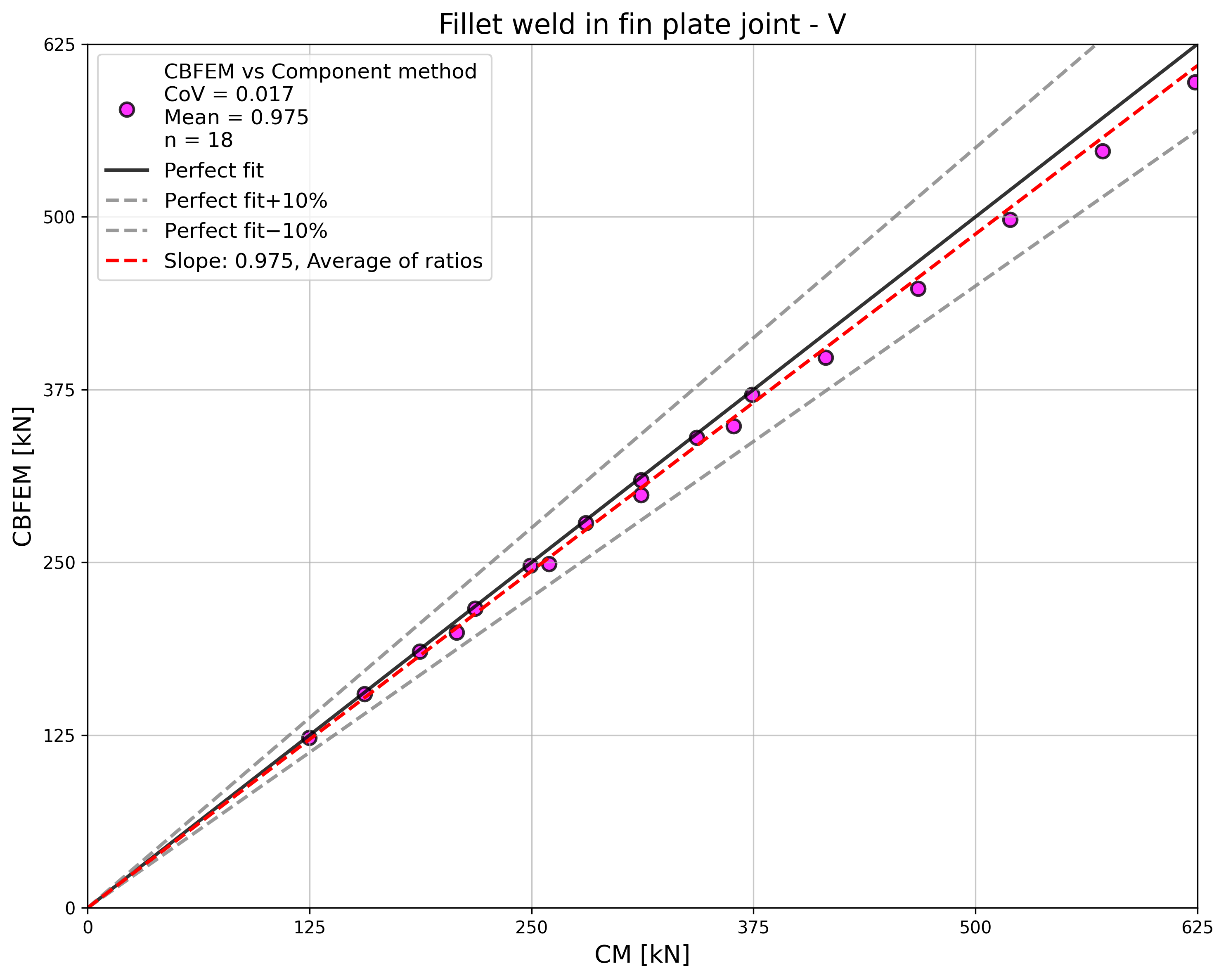
ความต้านทานการออกแบบที่คำนวณโดย CBFEM ถูกเปรียบเทียบกับผลลัพธ์ของ CM การเปรียบเทียบแสดงไว้ในตาราง 4.3.2 การศึกษาดำเนินการสำหรับพารามิเตอร์หนึ่งตัว ได้แก่ ความยาวรอยเชื่อม (ความสูงของแผ่น Fin) และกรณีแรงกระทำสามกรณี ได้แก่ แรงตามแนวแกน แรงเฉือน และโมเมนต์ดัด แรงเฉือนถูกกระทำในระนาบรอยเชื่อมเพื่อละเลยผลของโมเมนต์ดัดเพิ่มเติม โมเมนต์ดัดถูกกระทำที่ปลายของแผ่น Fin อิทธิพลของความยาวรอยเชื่อมต่อความต้านทานการออกแบบของจุดต่อแผ่น Fin ที่รับแรงตามแนวแกนและแรงเฉือนแสดงในรูปที่ 4.3.2 ความสัมพันธ์ระหว่างความยาวรอยเชื่อมและความต้านทานโมเมนต์ดัดของจุดต่อแสดงในรูปที่ 4.3.3
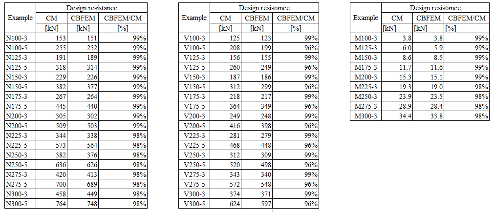
ผลลัพธ์ของ CBFEM และ CM ถูกเปรียบเทียบกัน และนำเสนอการศึกษาความไวต่อพารามิเตอร์ อิทธิพลของความยาวรอยเชื่อมต่อความต้านทานการออกแบบในจุดต่อแผ่น Fin ที่รับแรงตามแนวแกนแสดงในรูปที่ 4.3.2 ที่รับแรงเฉือนในรูปที่ 4.3.3 และที่รับโมเมนต์ดัดในรูปที่ 4.3.4 การศึกษาแสดงให้เห็นความสอดคล้องที่ดีสำหรับกรณีแรงกระทำทั้งหมดที่พิจารณา
เพื่อแสดงความแม่นยำของแบบจำลอง CBFEM ผลลัพธ์ของการศึกษาพารามิเตอร์ถูกสรุปในแผนภาพที่เปรียบเทียบความต้านทานการออกแบบของ CBFEM และ CM ดูรูปที่ 4.3.5 ผลลัพธ์แสดงให้เห็นว่าความแตกต่างระหว่างวิธีการคำนวณทั้งสองในทุกกรณีน้อยกว่า 10 %
ตัวอย่าง Benchmark
ข้อมูลนำเข้า
เสา
- เหล็ก S235
- HEB 400
แผ่น Fin
- ความหนา tp = 15 มม.
- ความสูง hp = 175 มม.
รอยเชื่อม รอยเชื่อมมุมคู่ ดูรูปที่ 4.3.6
- ความหนาคอ aw = 3 มม.
ผลลัพธ์
- ความต้านทานการออกแบบในการดัดล้วน MRd = 11.4 kNm
คำอธิบาย
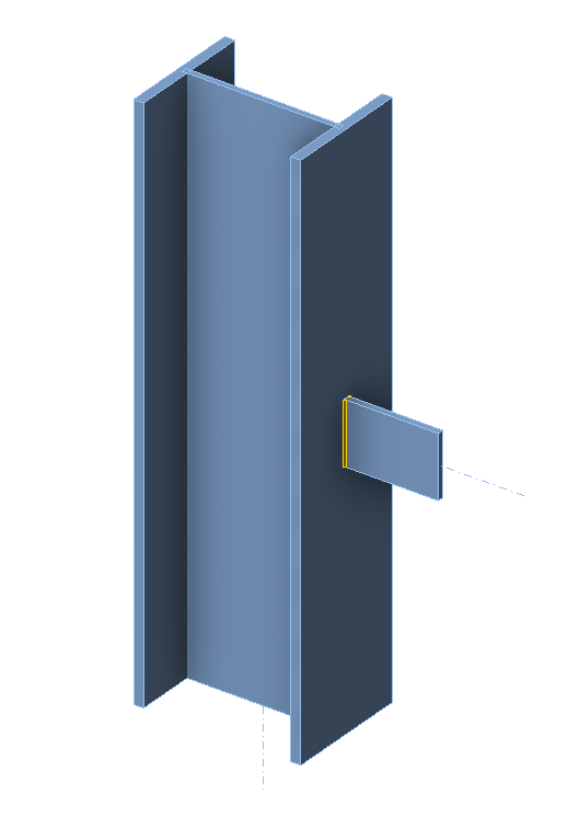
วัตถุประสงค์ของบทนี้คือการตรวจสอบวิธี Component-Based Finite Element (CBFEM) สำหรับรอยเชื่อมมุมในจุดต่อคานกับเสาแบบมีแผ่นเสริมความแข็ง โดยเปรียบเทียบกับวิธี Component Method (CM) คานหน้าตัดเปิด IPE ถูกเชื่อมต่อกับเสาหน้าตัดเปิด HEB400 โดยมีแผ่นเสริมความแข็งอยู่ภายในเสาตรงข้ามกับปีกคาน พารามิเตอร์ที่เปลี่ยนแปลงคือหน้าตัดของคาน โดยพิจารณาสามกรณีแรงกระทำ ได้แก่ คานรับแรงดึง แรงเฉือน และโมเมนต์ดัด
แบบจำลองเชิงวิเคราะห์
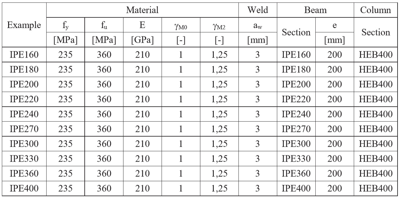
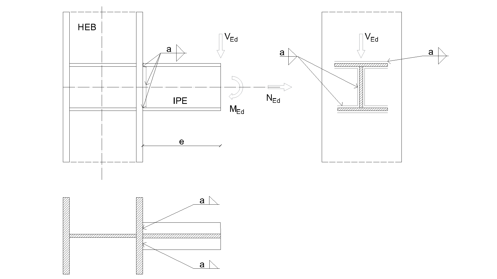
รอยเชื่อมมุมเป็นองค์ประกอบเดียวที่ศึกษาในงานวิจัยนี้ รอยเชื่อมได้รับการออกแบบตามบทที่ 4 ใน EN 1993-1-8:2005 ให้เป็นองค์ประกอบที่อ่อนแอที่สุดในจุดต่อ ความต้านทานการออกแบบของรอยเชื่อมมุมได้อธิบายไว้ใน หัวข้อ 4.1 ภาพรวมของตัวอย่างที่พิจารณาและวัสดุแสดงไว้ในตาราง 4.4.1 รูปทรงเรขาคณิตของจุดต่อพร้อมขนาดแสดงในรูปที่ 4.4.1
ตาราง 4.4.1 ภาพรวมตัวอย่าง
การคำนวณด้วยมือสำหรับแรงตามแนวแกน N
โดยที่:
- ความหนาคอรอยเชื่อม
- แรงตามแนวแกนที่กระทำบนคาน
- ความยาวรวมของรอยเชื่อม
- ตัวประกอบสหสัมพันธ์ที่นำมาจากตาราง 4.1 ใน EN 1993-1-8
- ความต้านทานแรงดึงประลัยของชิ้นส่วนที่อ่อนแอกว่าที่เชื่อมต่อกัน
- ตัวประกอบความปลอดภัยบางส่วนสำหรับรอยเชื่อม
การคำนวณด้วยมือสำหรับแรงเฉือน V
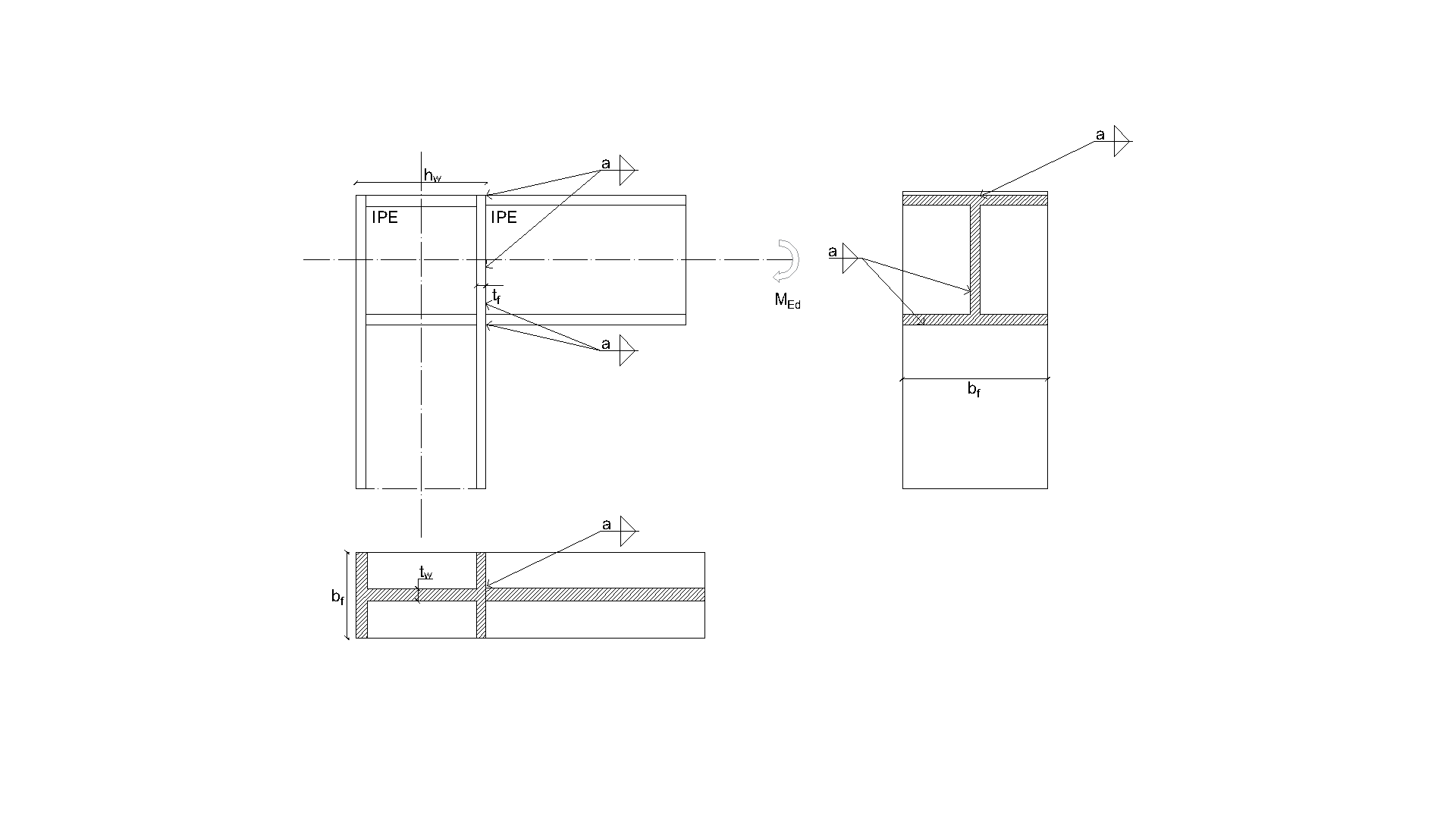
การคำนวณด้วยมือที่นำเสนอในบทนี้อยู่บนพื้นฐานของข้อสมมติบางประการ แรงเฉือน ถ่ายผ่านเฉพาะรอยเชื่อมที่เอว โมเมนต์ดัดที่เกิดจากความเยื้องศูนย์ของแรงที่กระทำบนรอยเชื่อมสามารถนำไปรวมกับรอยเชื่อมปีกได้ โมดูลัสหน้าตัดของรอยเชื่อมปีก ถูกกำหนดไม่ใช่จากระยะที่วัดจากจุดศูนย์ถ่วงของรอยเชื่อม แต่จากขอบปีกถึงจุดศูนย์ถ่วงของคาน ตามที่คำนวณในทางปฏิบัติ
สมการต่อไปนี้แสดงการหาความสามารถรับแรงของรอยเชื่อมสำหรับแรงเฉือนและโมเมนต์ดัดตาม CM ความเค้นสมมูลระบุไว้ใน EN 1993-1-8 สมการ (4.1) สำหรับการคำนวณความต้านทานโมเมนต์ดัด ได้สมมติใช้โมดูลัสหน้าตัดพลาสติก
โดยที่:
- ความเยื้องศูนย์ของแรงเทียบกับรอยเชื่อมคาน
- ความหนาคอรอยเชื่อม
- แรงเฉือนที่กระทำบนคาน
- โมดูลัสหน้าตัดของรอยเชื่อม
- พื้นที่รอยเชื่อมขอบปีกบน
- พื้นที่รอยเชื่อมขอบปีกล่าง
- แขนโมเมนต์รอยเชื่อมขอบปีกบน
- แขนโมเมนต์รอยเชื่อมขอบปีกล่าง
- โมดูลัสหน้าตัดพลาสติกของปีก
- ความยาวรวมของรอยเชื่อมเอว
- ตัวประกอบสหสัมพันธ์ที่นำมาจากตาราง 4.1 ใน EN 1993-1-8
- ความต้านทานแรงดึงประลัยของชิ้นส่วนที่อ่อนแอกว่าที่เชื่อมต่อกัน
- ตัวประกอบความปลอดภัยบางส่วนสำหรับรอยเชื่อม
- ความสูงคาน IPE
- ความกว้างคาน IPE
- ความหนาเอวคาน IPE
- ความหนาปีกคาน IPE
การคำนวณด้วยมือสำหรับโมเมนต์ดัด M
ในการคำนวณโมเมนต์ดัดโดยไม่มีปฏิสัมพันธ์กับแรงเฉือน ได้สมมติใช้โมดูลัสหน้าตัดพลาสติกของหน้าตัดรอยเชื่อมทั้งหมด (ทั้งรอบปีกและรอบเอว)
โดยที่:
- ความหนาคอรอยเชื่อม
- โมดูลัสหน้าตัดพลาสติกของรอยเชื่อม
- โมเมนต์ดัดที่กระทำบนคาน
- ตัวประกอบสหสัมพันธ์ที่นำมาจากตาราง 4.1 ใน EN 1993-1-8
- ความต้านทานแรงดึงประลัยของชิ้นส่วนที่อ่อนแอกว่าที่เชื่อมต่อกัน
- ตัวประกอบความปลอดภัยบางส่วนสำหรับรอยเชื่อม
แบบจำลองเชิงตัวเลข
องค์ประกอบรอยเชื่อมใน CBFEM ได้อธิบายไว้ใน พื้นฐานทางทฤษฎีทั่วไป และ พื้นฐานทางทฤษฎีตาม EN
วัสดุแบบ Nonlinear elastic-plastic ถูกใช้สำหรับรอยเชื่อมในการศึกษานี้ ความเครียดพลาสติกขีดจำกัดถูกบรรลุในส่วนที่ยาวกว่าของรอยเชื่อม และจุดสูงสุดของความเค้นจะถูกกระจายออกไป
การตรวจสอบความต้านทาน
ความต้านทานการออกแบบที่คำนวณโดยซอฟต์แวร์ CBFEM Idea RS ถูกเปรียบเทียบกับผลลัพธ์ของ CM ความต้านทานการออกแบบของรอยเชื่อมถูกเปรียบเทียบ ดูตาราง 4.4.2 การศึกษาดำเนินการสำหรับพารามิเตอร์หน้าตัดคานหนึ่งค่าและสามกรณีแรงกระทำ ได้แก่ แรงตามแนวแกน NEd แรงเฉือน VEd และโมเมนต์ดัด MEd
ตาราง 4.4.2 การเปรียบเทียบ CBFEM และ CM
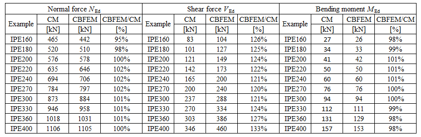
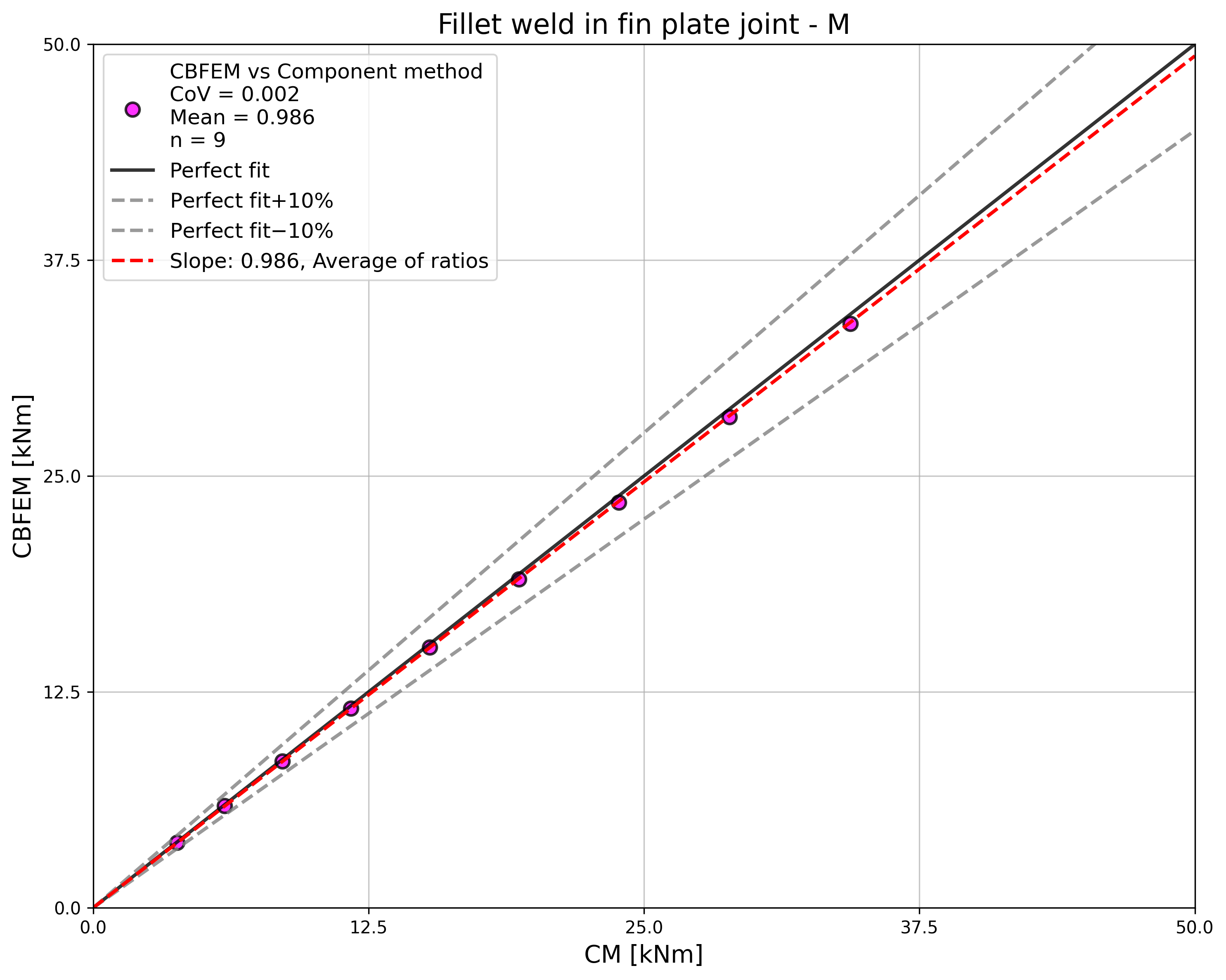
ผลลัพธ์ของ CBFEM และ CM ถูกเปรียบเทียบและนำเสนอการศึกษาความไว อิทธิพลของหน้าตัดคานต่อความต้านทานการออกแบบของจุดต่อคานกับเสาแบบเชื่อมที่รับแรงดึงแสดงในรูปที่ 4.4.2 รับแรงเฉือนในรูปที่ 4.4.3 และรับโมเมนต์ดัดในรูปที่ 4.4.4 การศึกษาแสดงให้เห็นความสอดคล้องที่ดีสำหรับทุกกรณีแรงกระทำที่พิจารณา
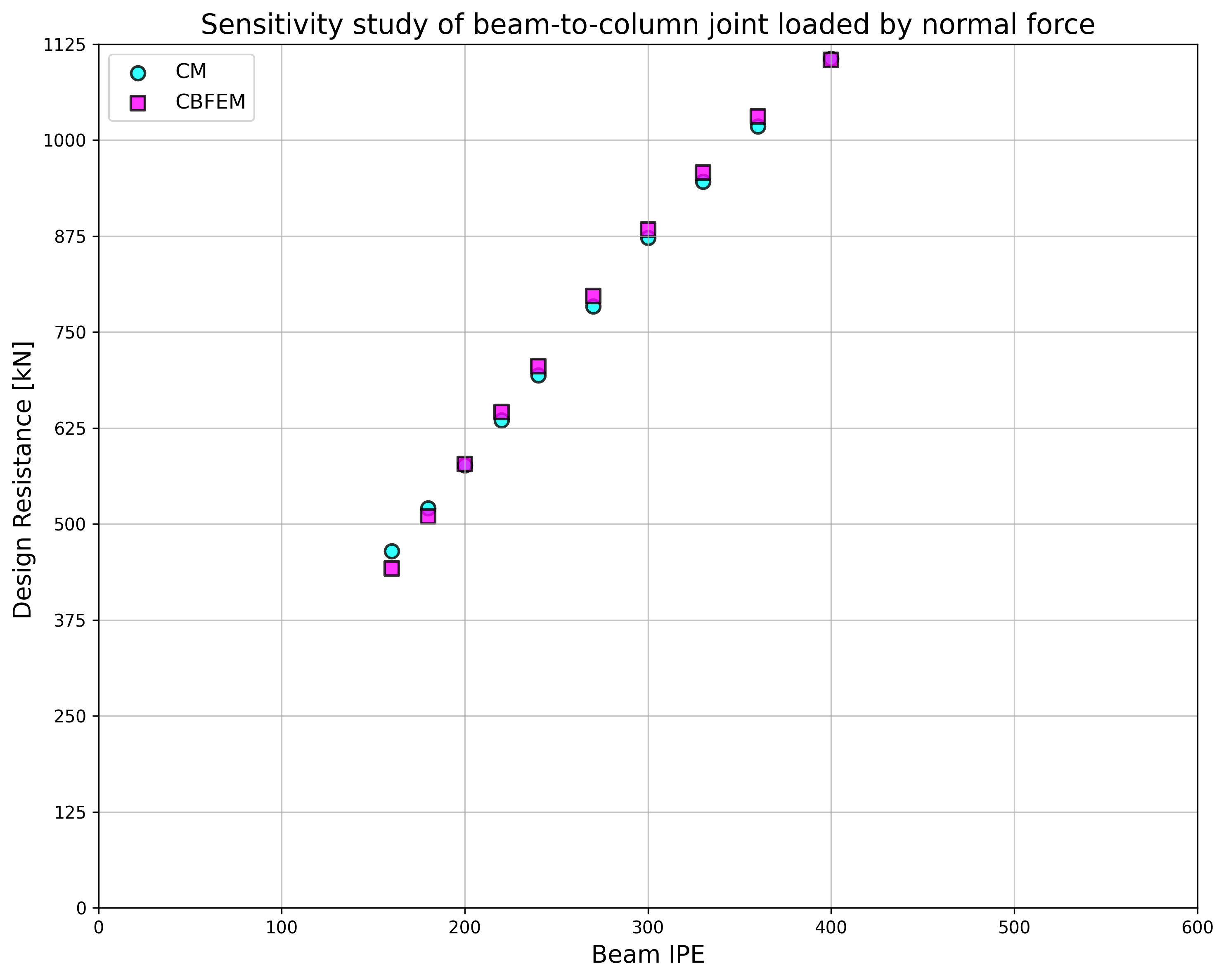
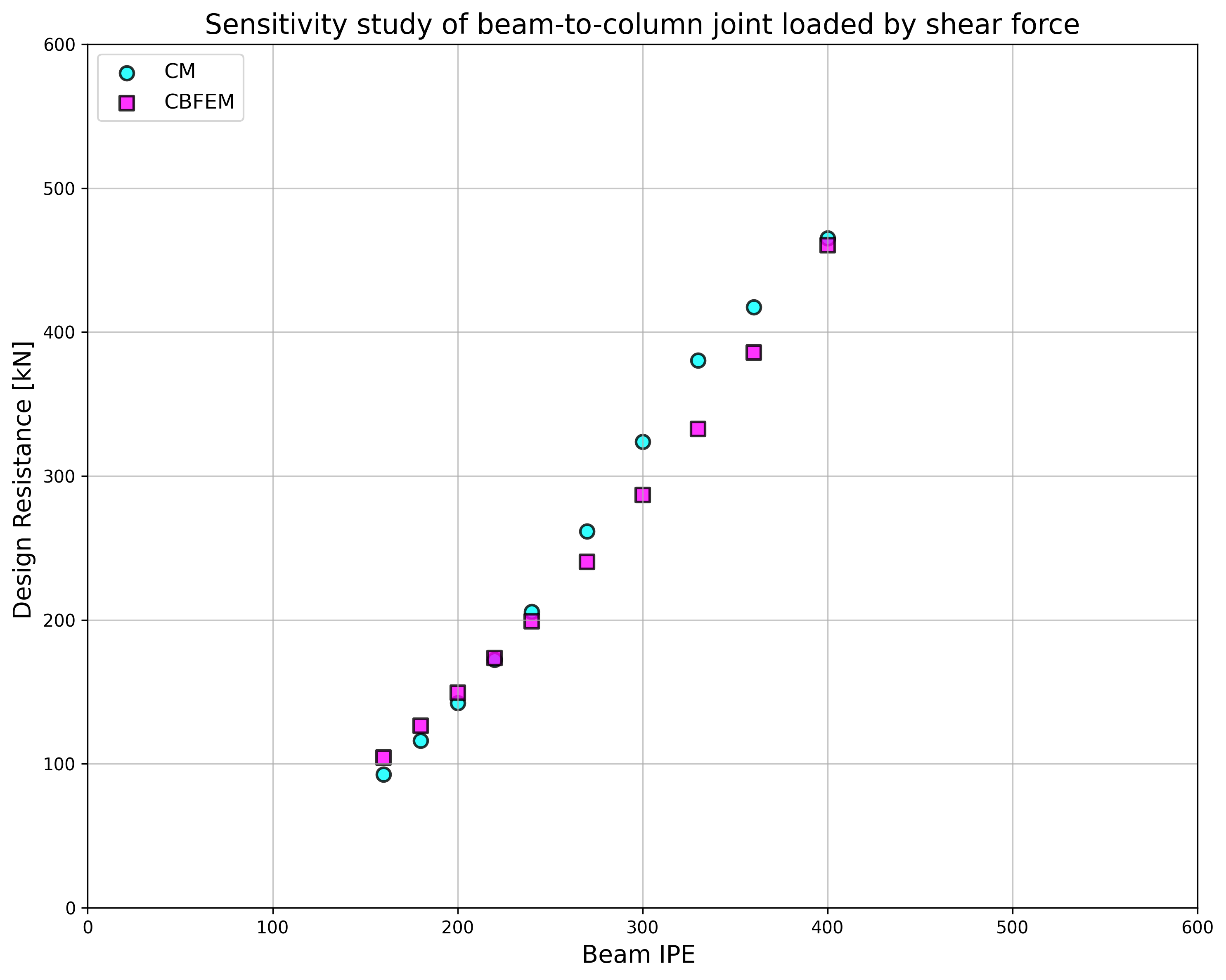
เพื่อแสดงให้เห็นความแม่นยำของแบบจำลอง CBFEM ผลลัพธ์ของการศึกษาความไวถูกสรุปในแผนภาพที่เปรียบเทียบความต้านทานการออกแบบของ CBFEM และ CM ดูรูปที่ 4.4.5 ผลลัพธ์แสดงให้เห็นว่าความแตกต่างของวิธีการคำนวณทั้งสองในทุกกรณีน้อยกว่า 10%
ตัวอย่างเปรียบเทียบมาตรฐาน
ข้อมูลนำเข้า
เสา
- เหล็ก S235
- HEB 400
คาน
- เหล็ก S235
- IPE 160
- ความเยื้องศูนย์ของแรงต่อรอยเชื่อม x = 400 mm ดูรูปที่ 4.4.6
รอยเชื่อม
- ความหนาคอรอยเชื่อม aw = 3 mm
ผลลัพธ์:
- ความต้านทานการออกแบบต่อแรงเฉือน VRd = 105 kN
คำอธิบาย
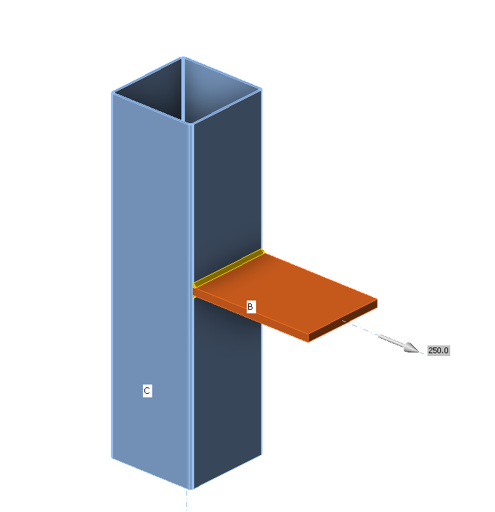
ในบทนี้ วิธี Component-Based Finite Element (CBFEM) ของรอยเชื่อมต่อเนื่องที่เชื่อมแผ่นเหล็กกับเสาที่ไม่มีแผ่นเสริมความแข็งได้รับการตรวจสอบโดยเปรียบเทียบกับวิธีส่วนประกอบ (CM) แผ่นเหล็กถูกเชื่อมต่อกับเสาหน้าตัดเปิดและหน้าตัดกล่อง และรับแรงดึง
แบบจำลองเชิงวิเคราะห์
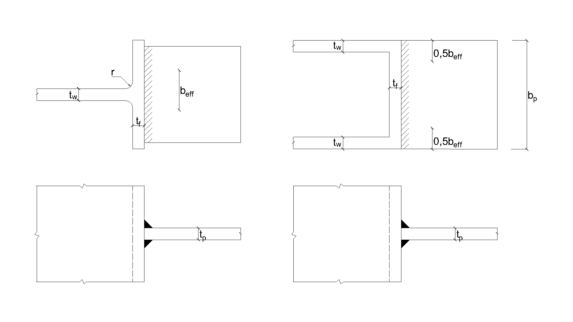
รอยเชื่อมต่อเนื่องเป็นส่วนประกอบเดียวที่ศึกษาในงานนี้ รอยเชื่อมได้รับการออกแบบตามบทที่ 4 ใน EN 1993-1-8:2005 ให้เป็นส่วนประกอบที่อ่อนแอที่สุดในจุดต่อ ความต้านทานการออกแบบของรอยเชื่อมต่อเนื่องอธิบายไว้ใน หัวข้อ 4.1 แรงที่กระทำตั้งฉากกับแผ่นที่ยืดหยุ่นได้ซึ่งเชื่อมกับหน้าตัดที่ไม่มีแผ่นเสริมความแข็งมีค่าจำกัด ความเค้นจะกระจุกตัวอยู่ในความกว้างประสิทธิผล ในขณะที่ความต้านทานของรอยเชื่อมรอบส่วนที่ไม่มีแผ่นเสริมความแข็งจะถูกละเลย ดังแสดงในรูปที่ 4.5.1 สำหรับหน้าตัด I หรือ H ที่ไม่มีแผ่นเสริมความแข็ง ความกว้างประสิทธิผลได้จาก:
ค่า s สำหรับหน้าตัดรีดร้อนคือ และสำหรับหน้าตัดเชื่อมคือ สำหรับหน้าตัดกล่องหรือหน้าตัดรางน้ำ ความกว้างประสิทธิผลควรได้จาก:
โดยที่:
- ความหนาคอรอยเชื่อม
- แรงปกติที่กระทำบนคาน
- ความยาวรอยเชื่อมประสิทธิผลรวม
- ตัวประกอบสหสัมพันธ์ที่นำมาจากตารางที่ 4.1 ใน EN 1993-1-8
- กำลังดึงประลัยที่กำหนดของชิ้นส่วนที่อ่อนแอกว่าที่เชื่อมต่อกัน
- ตัวประกอบความปลอดภัยบางส่วนสำหรับรอยเชื่อม
แบบจำลองเชิงตัวเลข
ส่วนประกอบรอยเชื่อมใน CBFEM อธิบายไว้ใน พื้นฐานทางทฤษฎีทั่วไป และ พื้นฐานทางทฤษฎีตาม EN สาขาพลาสติกถูกบรรลุในส่วนหนึ่งของรอยเชื่อม และยอดความเค้นถูกกระจายตลอดความยาวรอยเชื่อม
การตรวจสอบความต้านทาน
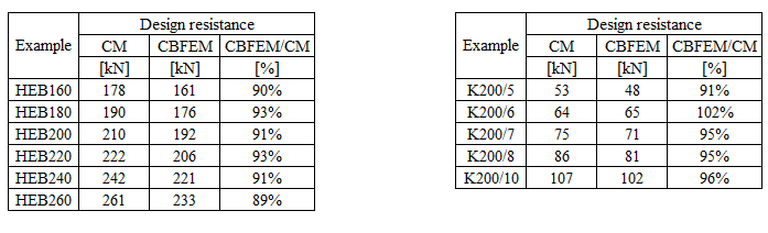
ความต้านทานการออกแบบที่คำนวณโดย CBFEM ถูกเปรียบเทียบกับผลลัพธ์ของ CM โดยเปรียบเทียบเฉพาะความต้านทานการออกแบบของรอยเชื่อม ภาพรวมของตัวอย่างที่พิจารณาและวัสดุแสดงไว้ในตารางที่ 4.5.1 รูปทรงเรขาคณิตของจุดต่อพร้อมขนาดแสดงในรูปที่ 4.5.2
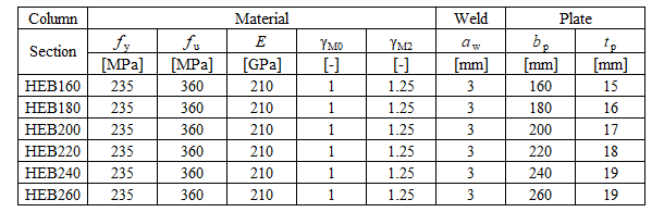
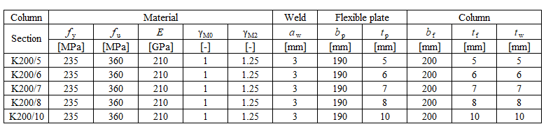
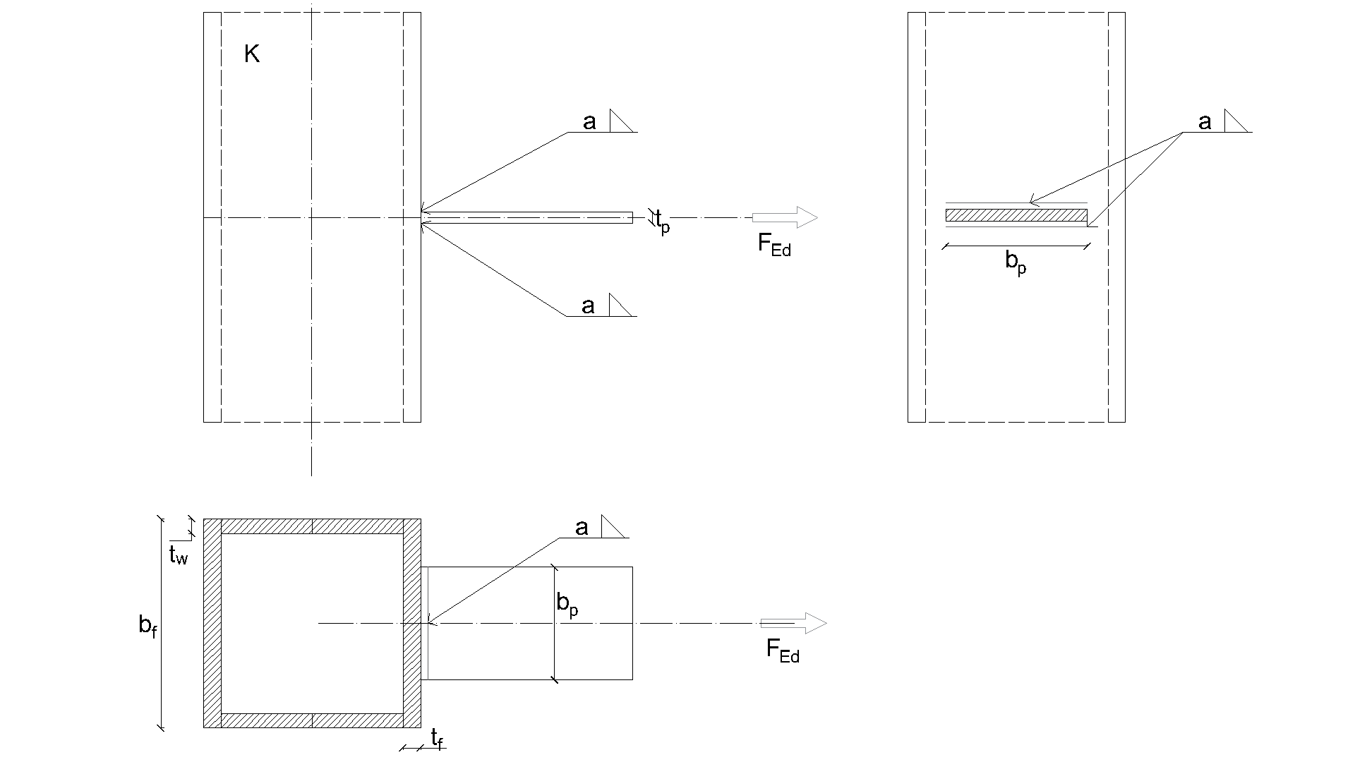
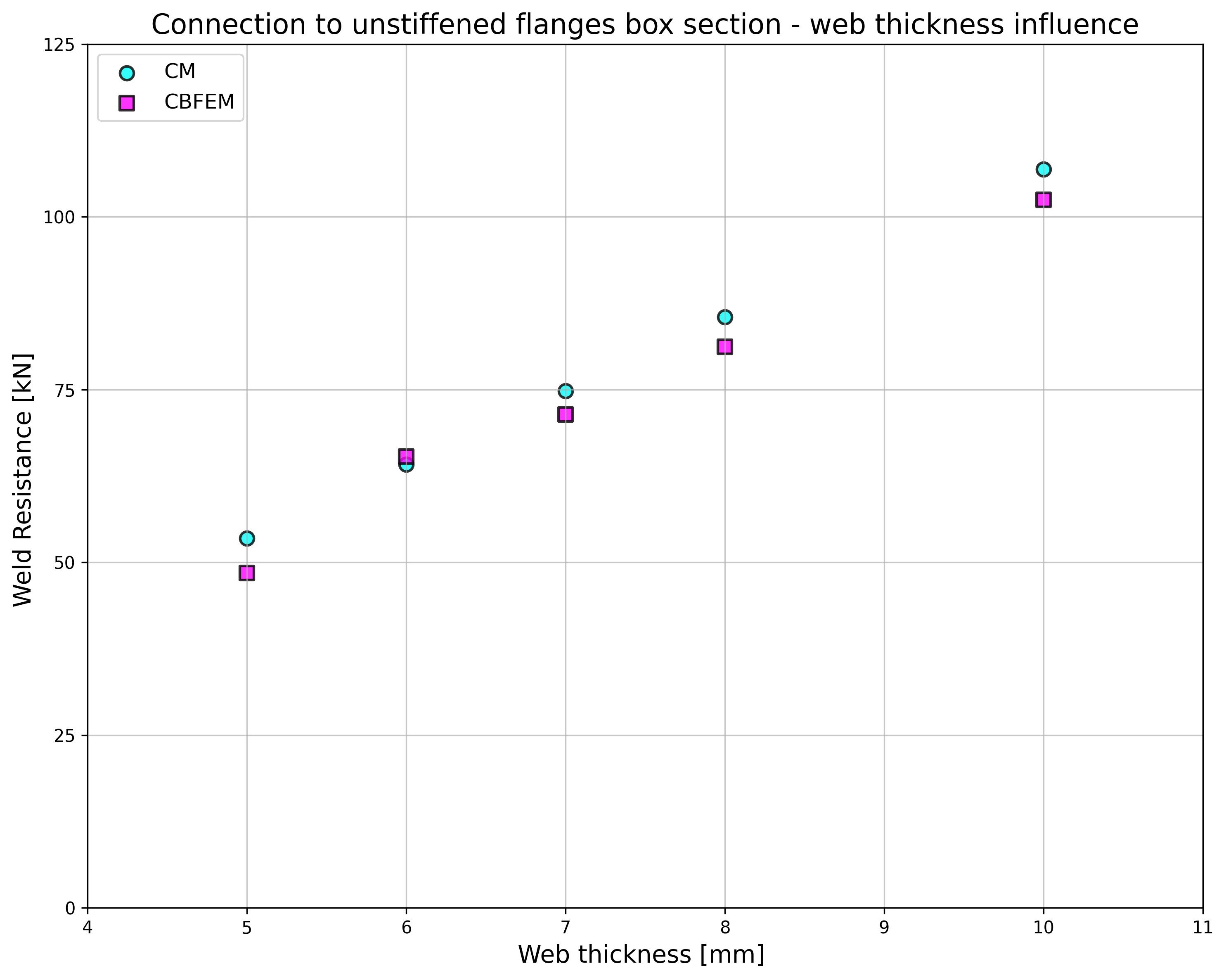
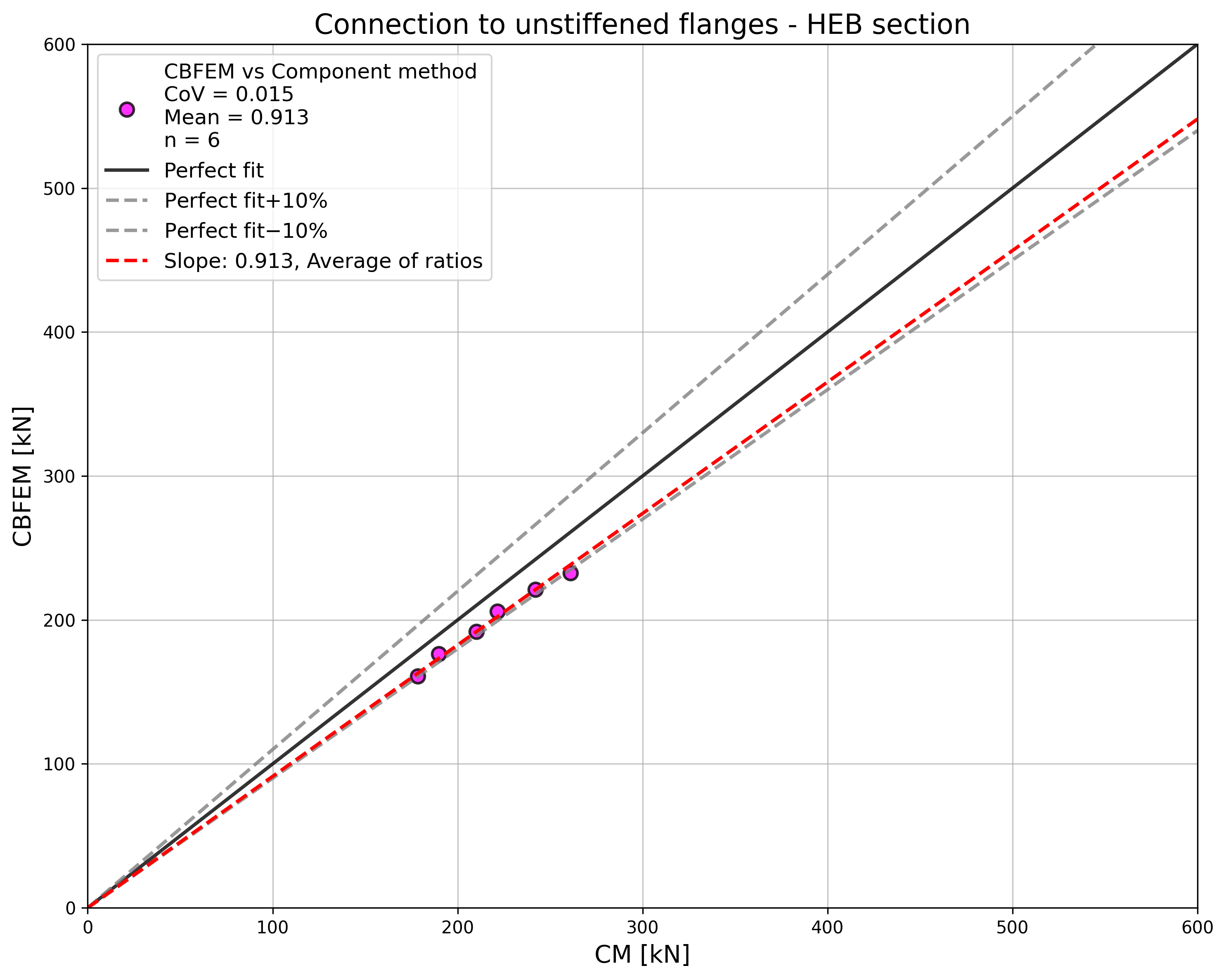
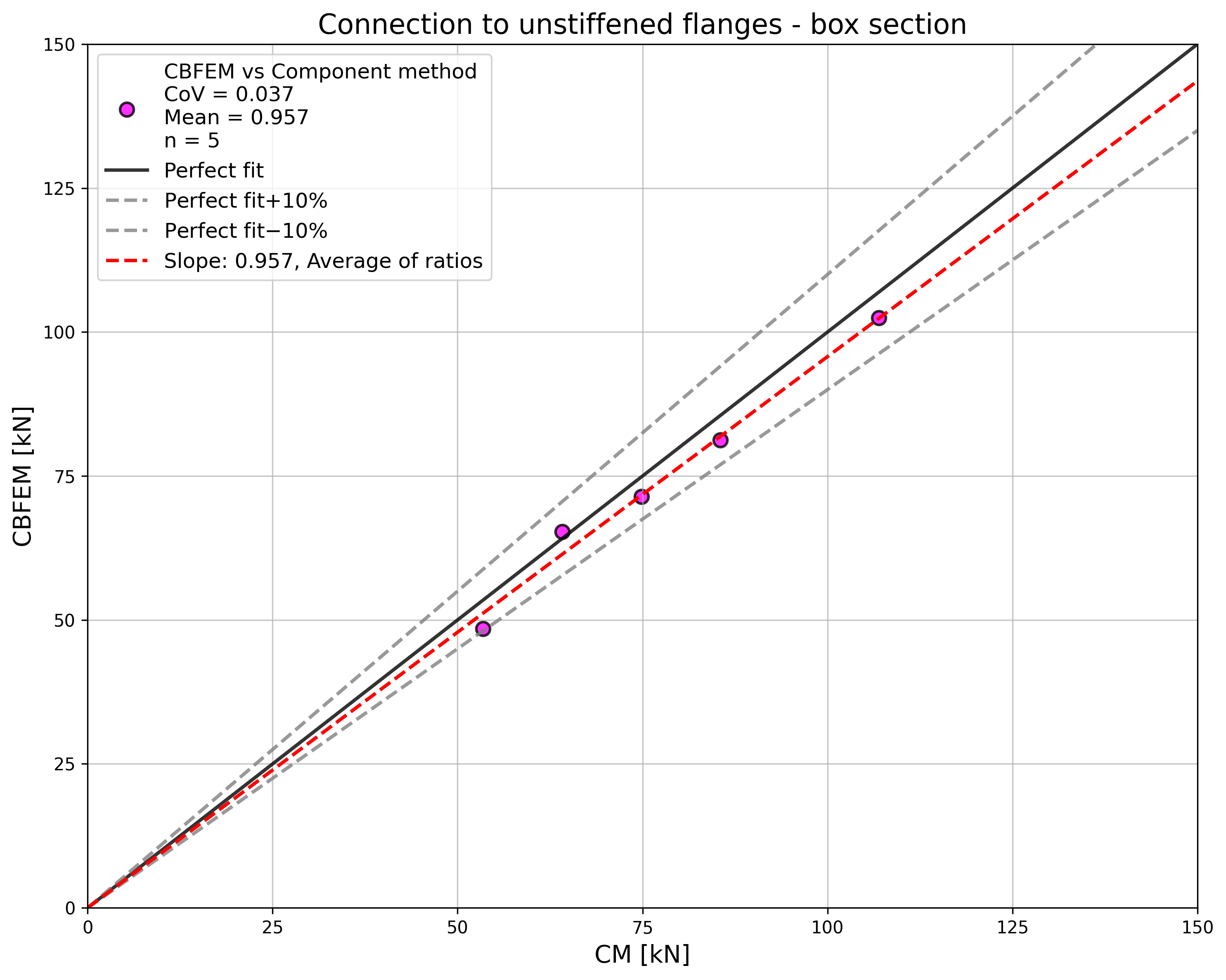
ผลลัพธ์แสดงไว้ในตารางที่ 4.5.2 การศึกษาดำเนินการสำหรับสองพารามิเตอร์ ได้แก่ ความกว้างปีกของหน้าตัด HEB และความหนาเอวของหน้าตัดกล่อง แผ่นที่ยืดหยุ่นได้รับแรงดึง อิทธิพลของความกว้างปีกของหน้าตัด HEB ต่อความต้านทานการออกแบบของจุดต่อแสดงในรูปที่ 4.5.3 ความสัมพันธ์ระหว่างความหนาเอวของหน้าตัดกล่องกับความต้านทานการออกแบบของจุดต่อแสดงในรูปที่ 4.5.4
ผลลัพธ์ของ CBFEM และ CM ถูกเปรียบเทียบในการศึกษาความไว อิทธิพลของความกว้างปีกของหน้าตัด HEB ต่อความต้านทานการออกแบบของจุดต่อศึกษาในรูปที่ 4.5.3 อิทธิพลของความหนาเอวของหน้าตัดกล่องต่อความต้านทานการออกแบบของจุดต่อแสดงในรูปที่ 4.5.4 การศึกษาเชิงพารามิเตอร์แสดงให้เห็นความสอดคล้องที่ดีมากของผลลัพธ์สำหรับการกำหนดค่ารอยเชื่อมทั้งหมด
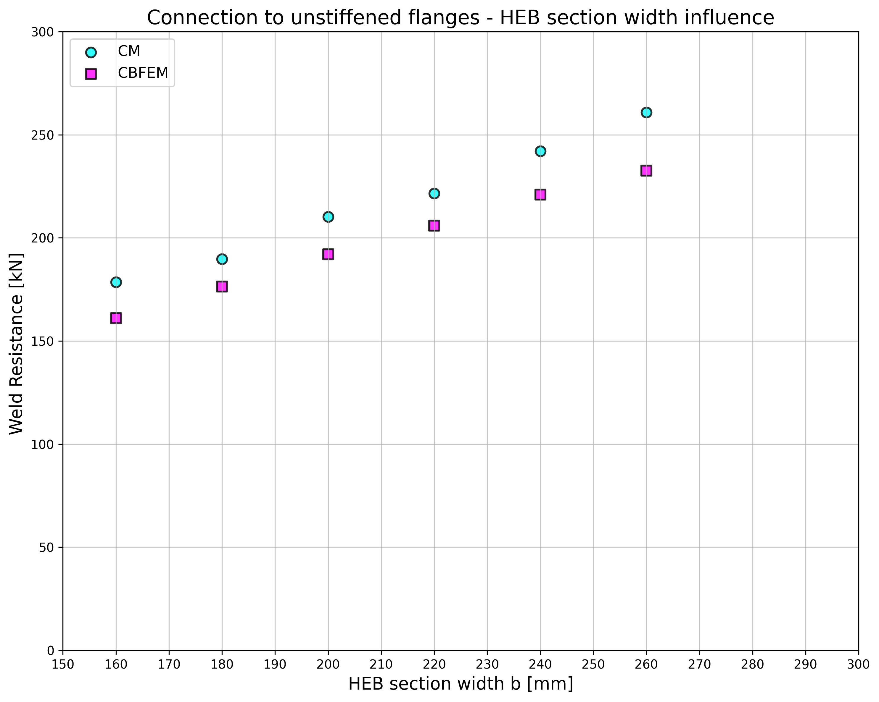
ผลลัพธ์ของการศึกษาความไวถูกสรุปในแผนภาพที่เปรียบเทียบความต้านทานการออกแบบของ CBFEM และ CM ดูรูปที่ 4.5.5 ซึ่งแสดงความแม่นยำของแบบจำลอง CBFEM
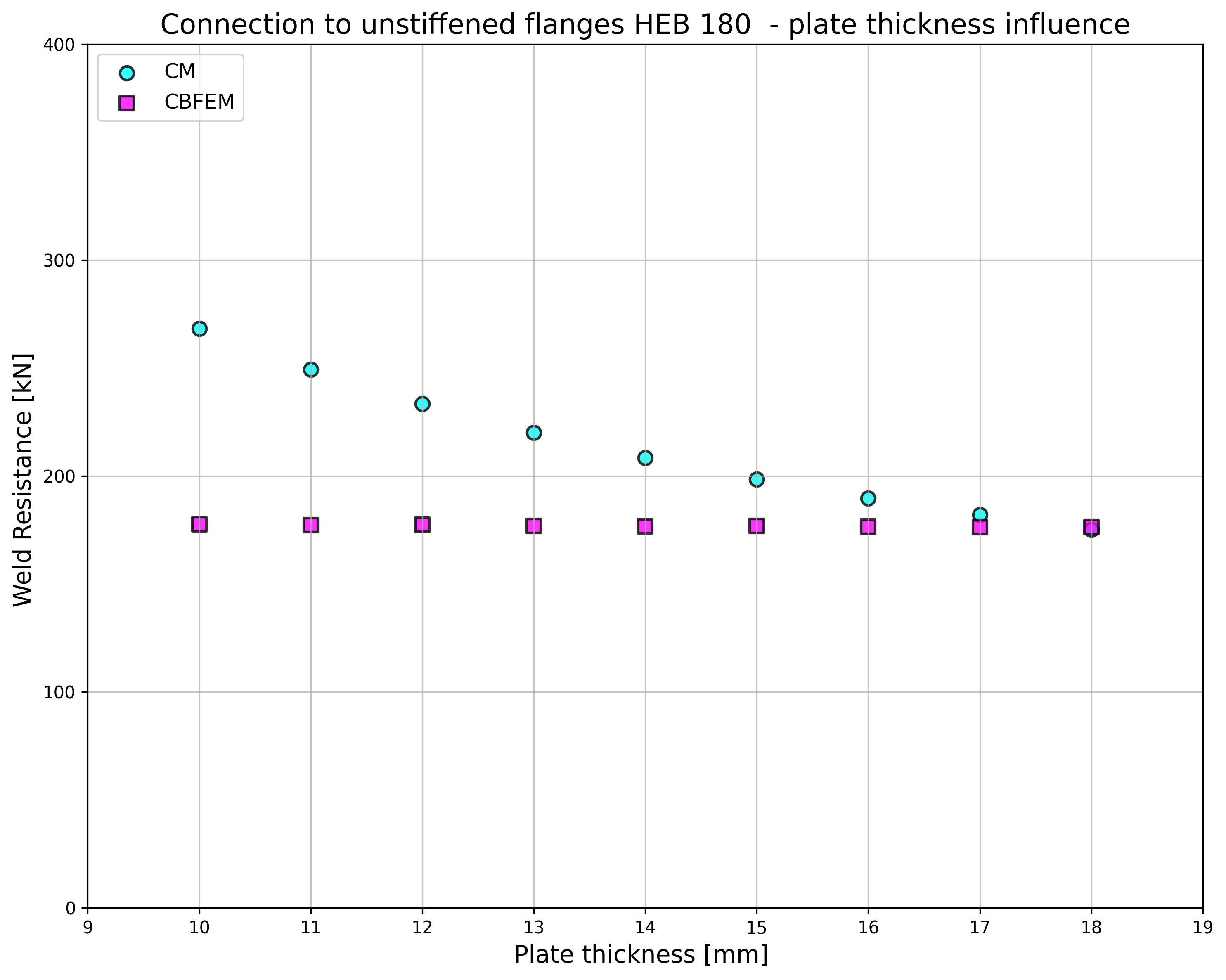
อิทธิพลของความหนาแผ่นต่อความต้านทานการออกแบบของรอยเชื่อมแสดงในรูปที่ 4.5.6 หน้าตัดเสาคือ HEB 180 ที่มีความหนาปีก 14 มม. รอยเชื่อมที่เชื่อมแผ่นที่หนากว่าปีกเสามีความต้านทานเท่ากันสำหรับ CM และ CBFEM ในทางกลับกัน รอยเชื่อมที่เชื่อมแผ่นกับปีกเสาที่มีความหนาเท่ากันหรือน้อยกว่ามีความต้านทานการออกแบบในแบบจำลองเชิงตัวเลขน้อยกว่า 20% ความหนาของแผ่นไม่ได้ถูกนำมาพิจารณาในแบบจำลองเชิงตัวเลขที่ใช้ Shell element ซึ่งเป็นสาเหตุของความแตกต่างนี้
ตัวอย่าง Benchmark
ข้อมูลนำเข้า
เสา
• เหล็ก S235
• RHS 200/200/5
แผ่นที่ยืดหยุ่น
• เหล็ก S235
• ความหนา tp = 17 มม.
• ความกว้าง bp = 190 มม.
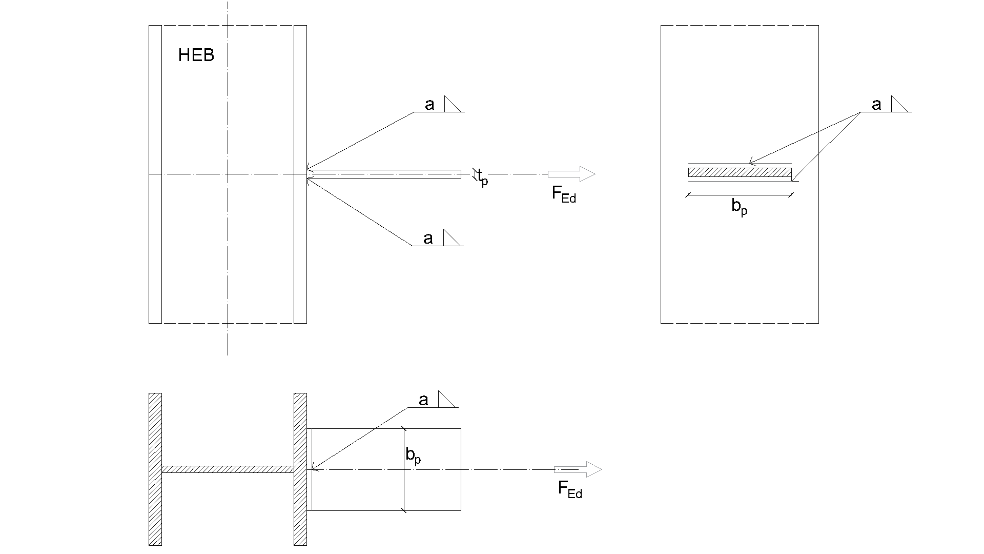
รอยเชื่อม รอยเชื่อมต่อเนื่องสองด้าน ดูรูปที่ 4.5.7
• ความหนาคอรอยเชื่อม aw = 5 มม.
ผลลัพธ์
• ความต้านทานการออกแบบในแรงดึง NRd = 68 kN
การเชื่อมต่อโครงสร้างเหล็กแบบสลักเกลียว
คำอธิบาย
วัตถุประสงค์ของบทนี้คือการตรวจสอบวิธี Component-Based Finite Element (CBFEM) ของ T-stub ที่เชื่อมต่อด้วยสลักเกลียวสองตัวรับแรงดึง โดยเปรียบเทียบกับวิธี Component Method (CM) และแบบจำลอง FEM เพื่อการวิจัย (RM) ที่สร้างในซอฟต์แวร์ Midas FEA ดู (Gödrich et al. 2019)
แบบจำลองเชิงวิเคราะห์
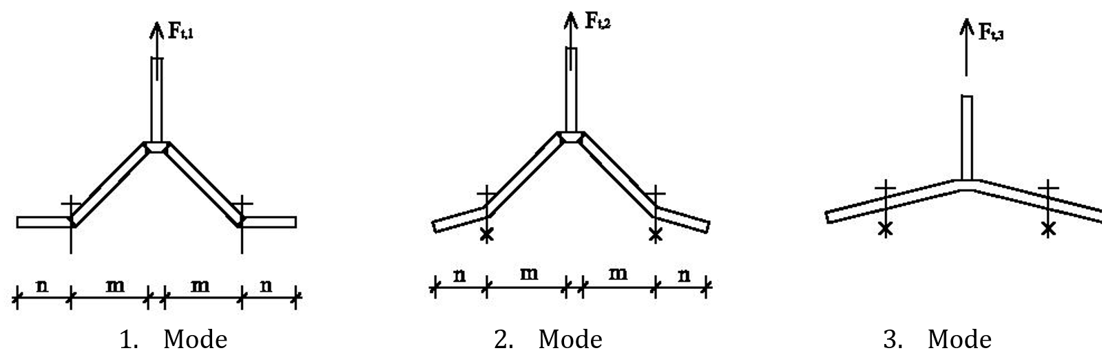
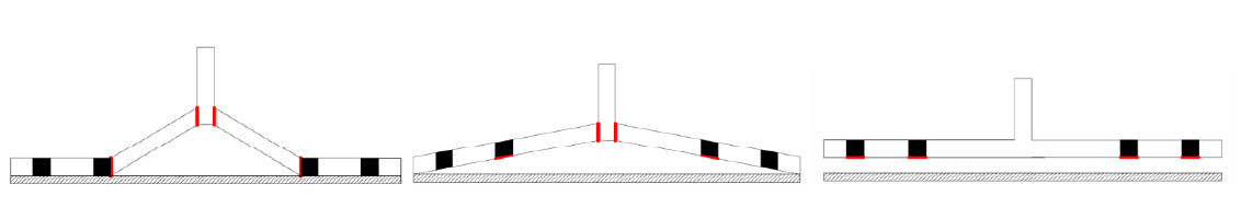
T-stub แบบเชื่อมและสลักเกลียวรับแรงดึงเป็นองค์ประกอบที่ศึกษาในงานนี้ ทั้งสององค์ประกอบได้รับการออกแบบตาม EN 1993-1-8:2005 รอยเชื่อมได้รับการออกแบบให้ไม่เป็นองค์ประกอบที่อ่อนแอที่สุด ความยาวประสิทธิผลสำหรับการวิบัติแบบวงกลมและไม่ใช่วงกลมพิจารณาตาม EN 1993-1-8:2005 ข้อ 6.2.6 พิจารณาเฉพาะแรงดึงเท่านั้น โหมดการวิบัติสามโหมดตาม EN 1993-1-8:2005 ข้อ 6.2.4.1 ได้แก่ 1. โหมดที่มีการครากเต็มที่ของปีก 2. โหมดที่มีเส้นครากสองเส้นที่เอวและการแตกหักของสลักเกลียว และ 3. โหมดการแตกหักของสลักเกลียว ดูรูปที่ 5.1.1 สลักเกลียวได้รับการออกแบบตามข้อ 3.6.1 ใน EN 1993-1-8:2005 ความต้านทานการออกแบบพิจารณาความต้านทานแรงเฉือนแบบ Punching และการแตกหักของสลักเกลียว
แบบจำลองเชิงตัวเลขสำหรับการออกแบบ
T-stub ถูกจำลองด้วยองค์ประกอบเปลือก 4 โหนด ตามที่อธิบายในบทที่ 3 และสรุปเพิ่มเติมด้านล่าง แต่ละ Node มี 6 องศาอิสระ การเสียรูปของชิ้นส่วนประกอบด้วยส่วนสนับสนุนจากเมมเบรนและการดัด สถานะวัสดุแบบ Elastic-Plastic ไม่เชิงเส้นถูกตรวจสอบในแต่ละชั้นของจุดอินทิเกรชัน การประเมินผลอ้างอิงจากความเครียดสูงสุดตาม EN 1993‑1‑5:2006 ที่ค่า 5 % สลักเกลียวถูกแบ่งออกเป็นสามองค์ประกอบย่อย องค์ประกอบแรกคือก้านสลักเกลียว ซึ่งจำลองเป็น Spring ไม่เชิงเส้นและรับแรงดึงเท่านั้น องค์ประกอบย่อยที่สองถ่ายแรงดึงไปยังปีก องค์ประกอบย่อยที่สามแก้ปัญหาการถ่ายแรงเฉือน
แบบจำลองเชิงตัวเลขเพื่อการวิจัย
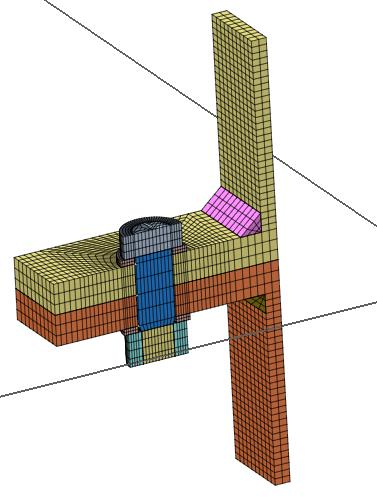
ในกรณีที่ CBFEM ให้ค่าความต้านทาน ความแข็งเริ่มต้น หรือความสามารถในการเสียรูปสูงกว่า จะใช้แบบจำลอง FEM เพื่อการวิจัย (RM) จากองค์ประกอบอิฐที่ได้รับการตรวจสอบความถูกต้องจากการทดลอง (Gödrich et al. 2013) เพื่อตรวจสอบแบบจำลอง CBFEM RM ถูกสร้างในซอฟต์แวร์ Midas FEA ด้วยองค์ประกอบของแข็งแบบ Hexahedral และ Octahedral ดูรูปที่ 5.1.2 การศึกษาความไวต่อขนาด Mesh ถูกดำเนินการเพื่อให้ได้ผลลัพธ์ที่เหมาะสมในเวลาที่เหมาะสม แบบจำลองเชิงตัวเลขของสลักเกลียวอ้างอิงจากแบบจำลองของ (Wu et al. 2012) เส้นผ่านศูนย์กลางระบุถูกพิจารณาในส่วนก้าน และเส้นผ่านศูนย์กลางแกนกลางประสิทธิผลถูกพิจารณาในส่วนเกลียว แผ่นรองถูกเชื่อมต่อกับหัวและน็อต การเสียรูปที่เกิดจากการลื่นของเกลียวในบริเวณสัมผัสระหว่างเกลียวและน็อตถูกจำลองด้วยองค์ประกอบ Interface องค์ประกอบ Interface ไม่สามารถถ่ายแรงดึงได้ องค์ประกอบ Contact ที่อนุญาตให้ถ่ายแรงดันและแรงเสียดทานถูกใช้ระหว่างแผ่นรองและปีกของ T-stub จำลองหนึ่งในสี่ของตัวอย่างโดยใช้สมมาตร
ขอบเขตความถูกต้อง
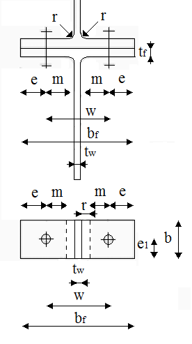
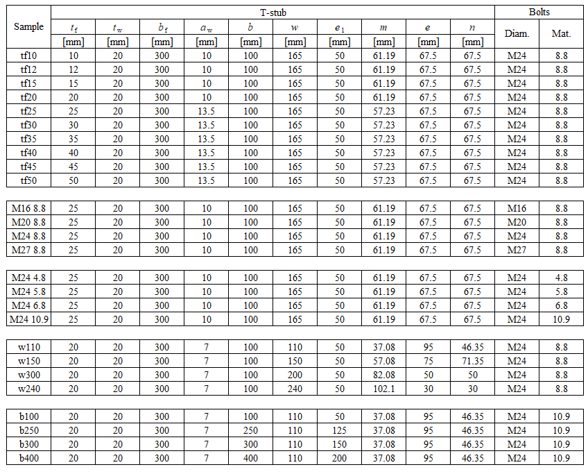
CBFEM ได้รับการตรวจสอบสำหรับรูปทรงเรขาคณิต T-stub ทั่วไปที่เลือกไว้ ความหนาขั้นต่ำของปีกคือ 8 mm ระยะห่างสูงสุดของสลักเกลียวต่อเส้นผ่านศูนย์กลางสลักเกลียวถูกจำกัดโดย p/db ≤ 20 ระยะห่างของแนวสลักเกลียวถึงเอวถูกจำกัดที่ m/db ≤ 5 ภาพรวมของตัวอย่างที่พิจารณาด้วยแผ่นเหล็ก S235: fy = 235 MPa, fu = 360 MPa, E = Ebolt = 210 GPa แสดงในตารางที่ 5.1.1 และรูปที่ 5.1.3
ตารางที่ 5.1.1 ภาพรวมของตัวอย่าง T-stub ที่พิจารณา
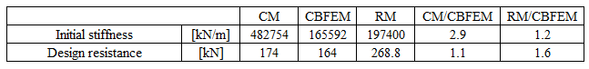
พฤติกรรมโดยรวม
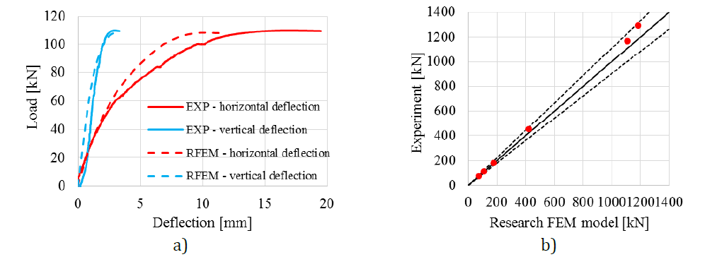
การเปรียบเทียบพฤติกรรมโดยรวมของ T-stub ที่อธิบายด้วยแผนภาพแรง-การเสียรูปสำหรับขั้นตอนการออกแบบทั้งหมดได้รับการจัดทำขึ้น ให้ความสนใจกับลักษณะสำคัญ ได้แก่ ความแข็งเริ่มต้น ความต้านทานการออกแบบ และความสามารถในการเสียรูป ตัวอย่าง tf20 ถูกเลือกเพื่อนำเสนอเป็นข้อมูลอ้างอิง ดูรูปที่ 5.1.4 และตารางที่ 5.1.2 CM โดยทั่วไปให้ความแข็งเริ่มต้นสูงกว่าเมื่อเปรียบเทียบกับ CBFEM และ RM ในทุกกรณี RM ให้ความต้านทานการออกแบบสูงสุด ดังที่แสดงในบทที่ 6 ความสามารถในการเสียรูปก็ถูกเปรียบเทียบด้วย ความสามารถในการเสียรูปของ T-stub คำนวณตาม (Beg et al. 2004) RM ไม่พิจารณาการแตกร้าวของวัสดุ ดังนั้นการทำนายความสามารถในการเสียรูปจึงมีข้อจำกัด
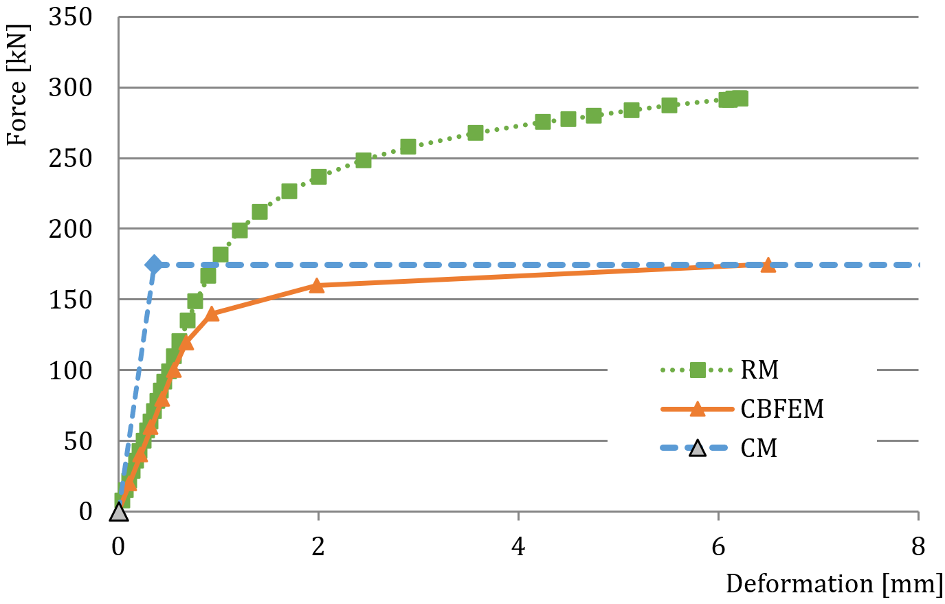
ตารางที่ 5.1.2 ภาพรวมพฤติกรรมโดยรวม
การตรวจสอบความต้านทาน
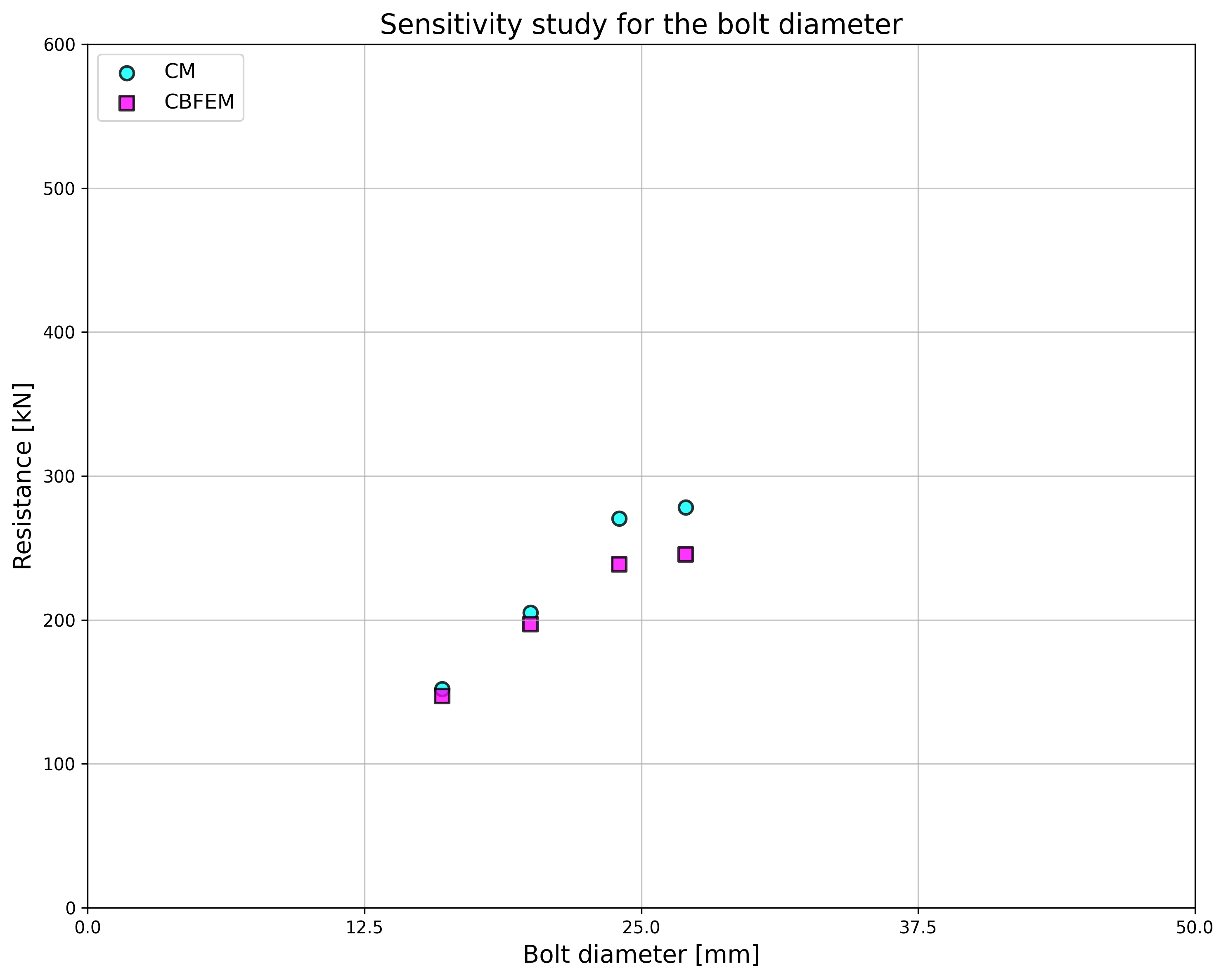
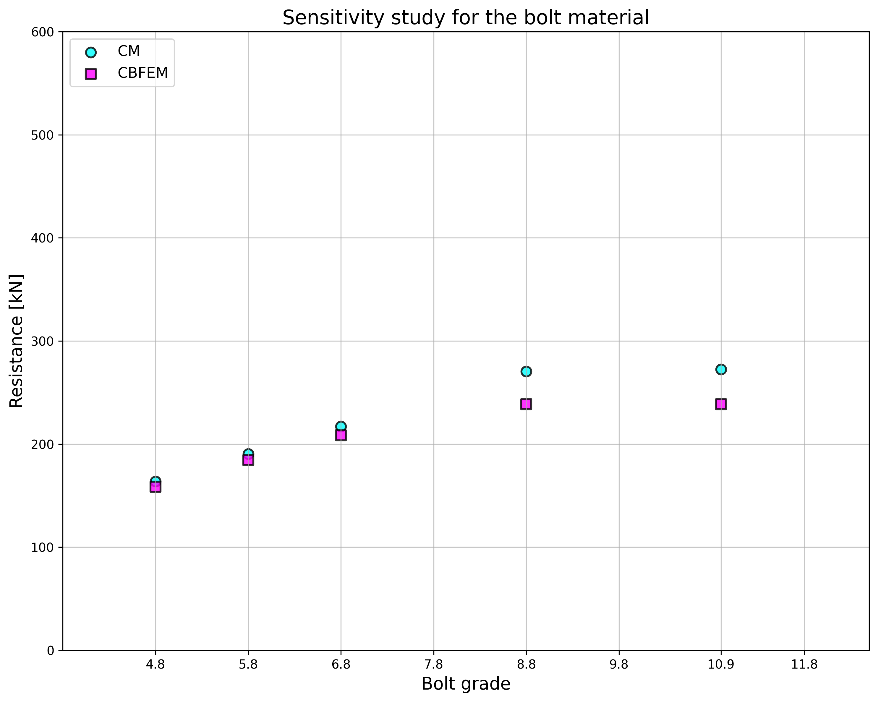
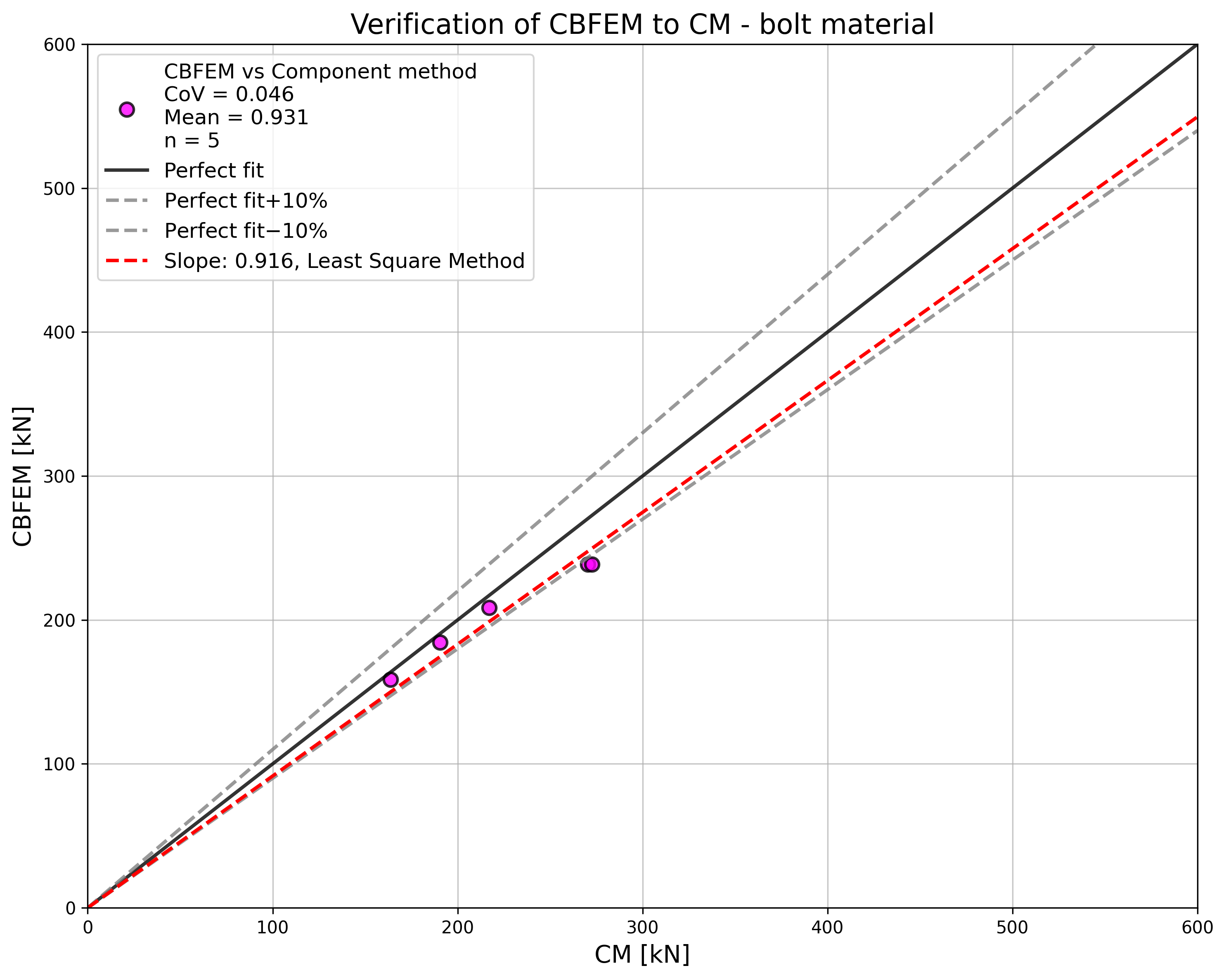
ความต้านทานการออกแบบที่คำนวณโดย CBFEM ถูกเปรียบเทียบกับผลลัพธ์ของ CM และ RM ในขั้นตอนถัดไป การเปรียบเทียบยังมุ่งเน้นไปที่ความสามารถในการเสียรูปและการระบุโหมดการวิบัติด้วย ผลลัพธ์ทั้งหมดเรียงลำดับในตารางที่ 5.1.3 การศึกษาดำเนินการสำหรับพารามิเตอร์ห้าตัว ได้แก่ ความหนาของปีก ขนาดสลักเกลียว วัสดุสลักเกลียว ระยะห่างสลักเกลียว และความกว้างของ T-stub
ตารางที่ 5.1.3 ภาพรวมพฤติกรรมโดยรวม
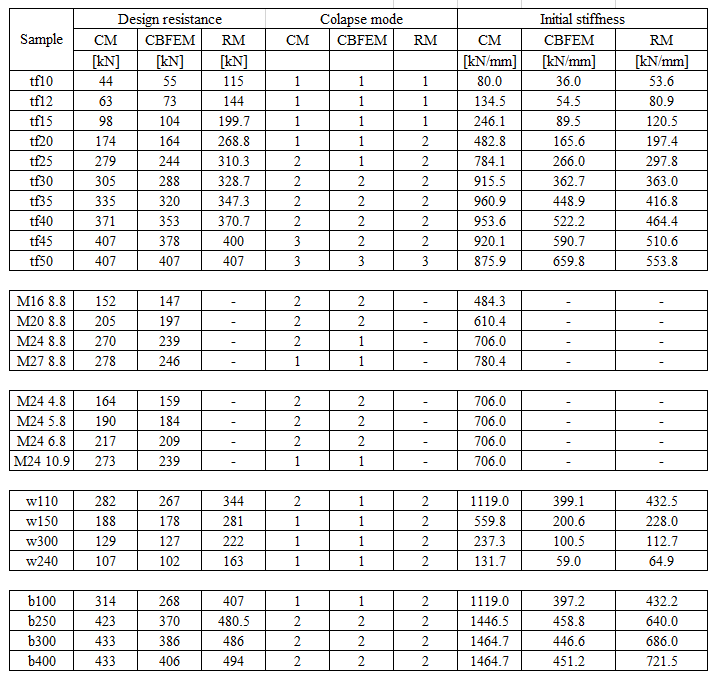
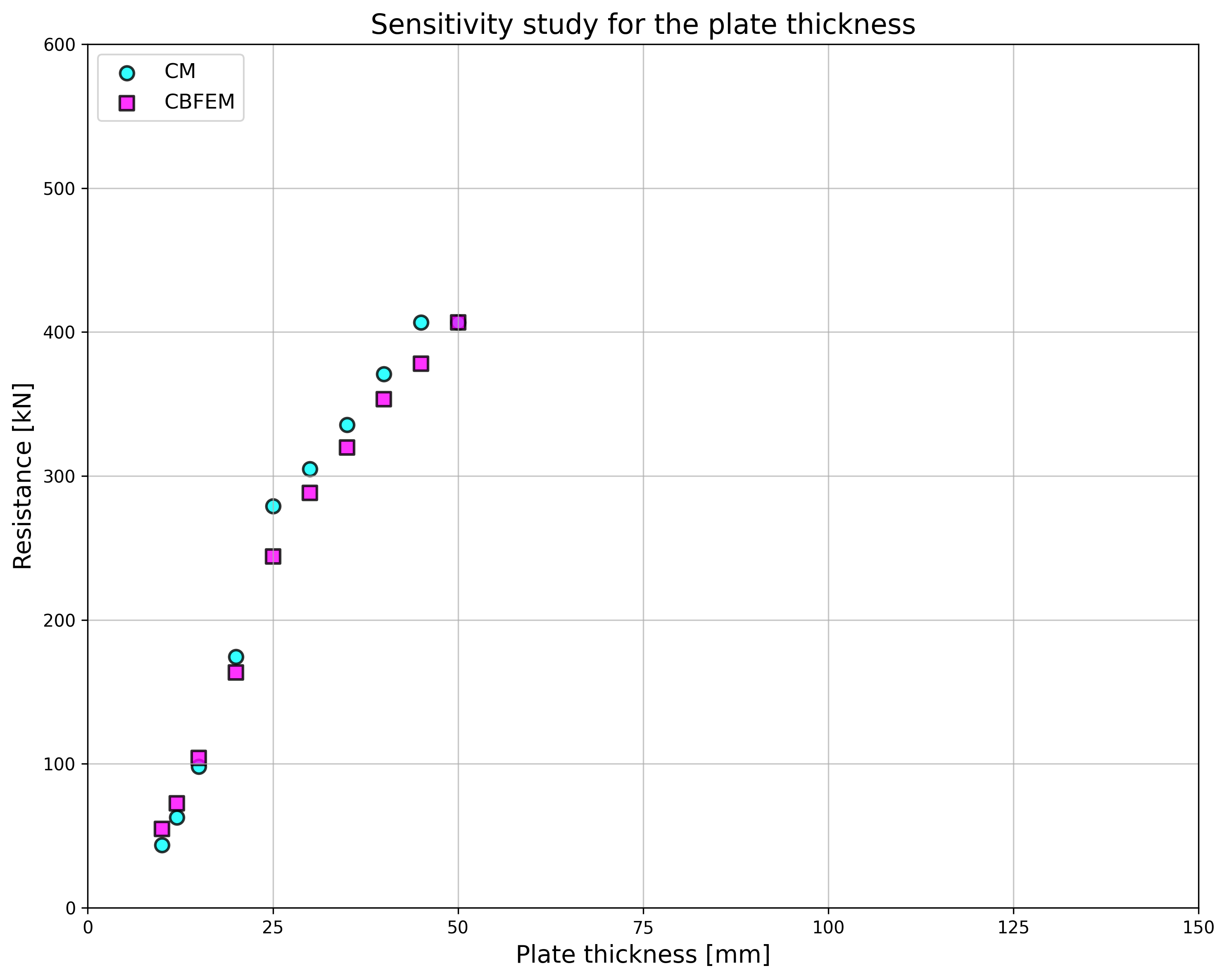
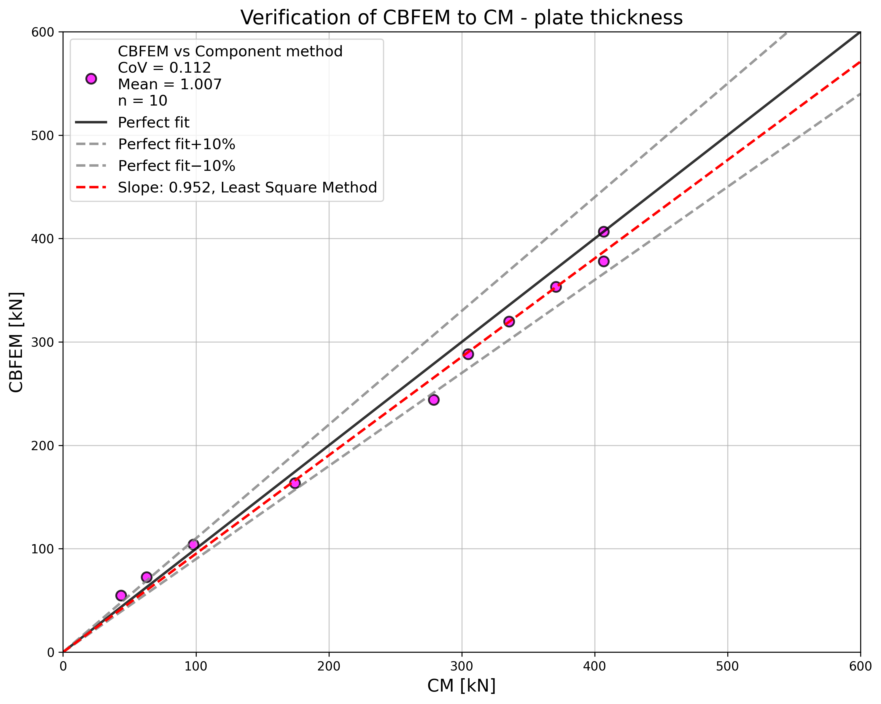
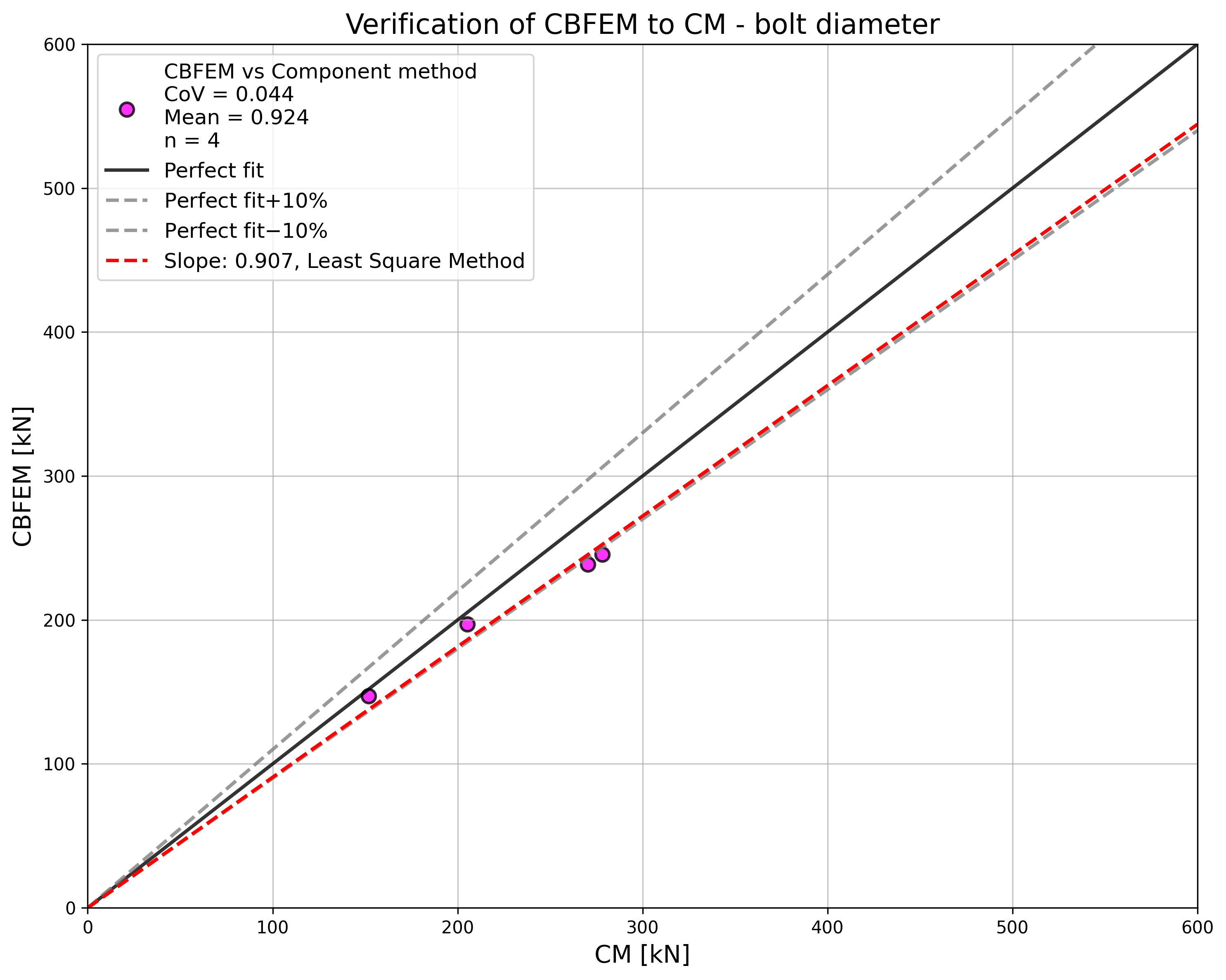
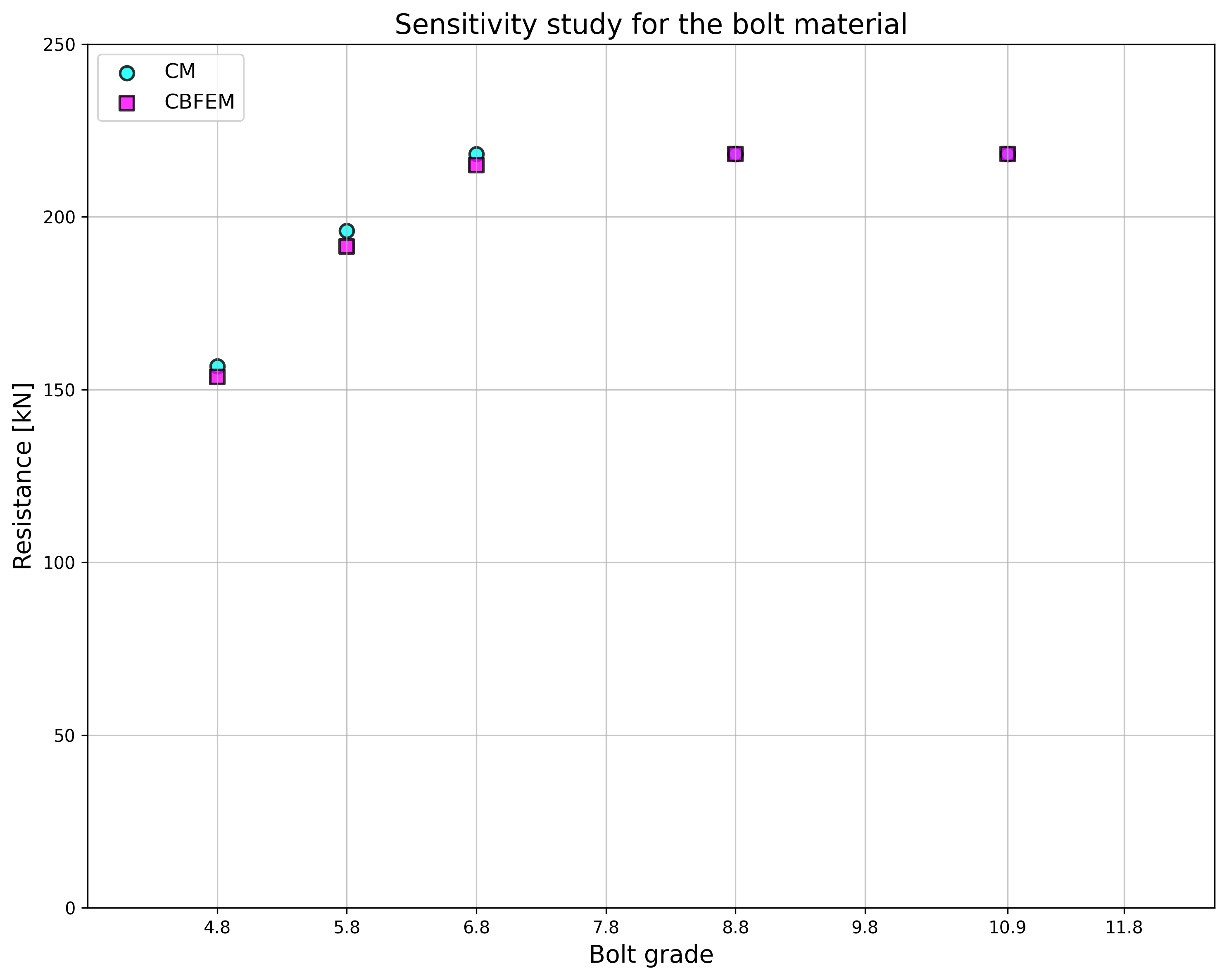
การศึกษาความไวต่อความหนาของปีกแสดงให้เห็นว่า CBFEM ให้ความต้านทานสูงกว่า CM สำหรับตัวอย่างที่มีความหนาปีกถึง 20 mm RM ให้ความต้านทานสูงกว่าสำหรับตัวอย่างเหล่านี้ ดูรูปที่ 5.1.5 ความต้านทานที่สูงกว่าของแบบจำลองเชิงตัวเลขทั้งสองอธิบายได้จากการละเลยผลของเมมเบรนใน CM ในกรณีของเส้นผ่านศูนย์กลางสลักเกลียวและวัสดุสลักเกลียว (ดูรูปที่ 5.1.6 และรูปที่ 5.1.7 ตามลำดับ) ผลลัพธ์ของ CBFEM สอดคล้องกับ CM เนื่องจากความสอดคล้องที่ดีของทั้งสองวิธี จึงไม่จำเป็นต้องใช้ผลลัพธ์ของ RM
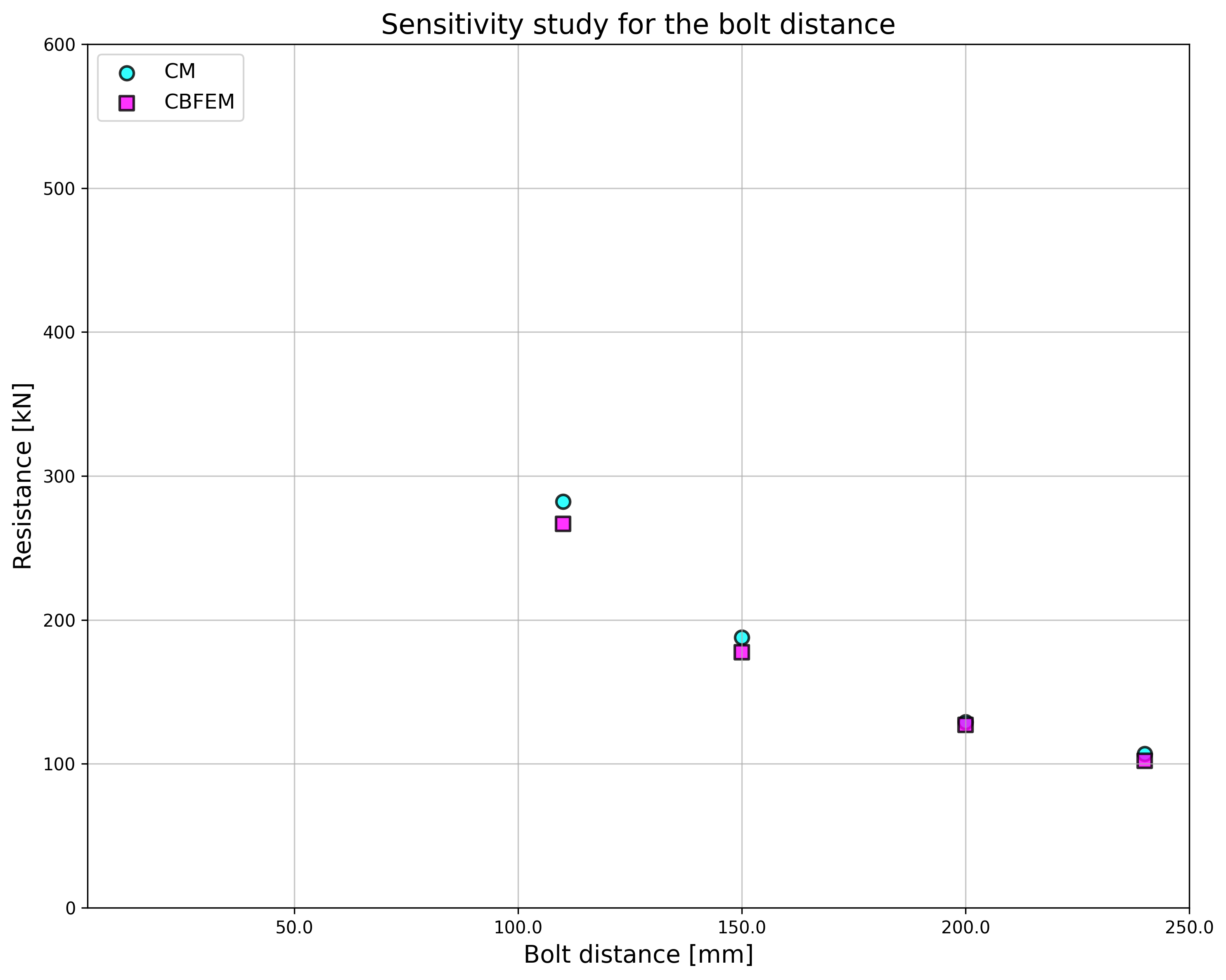
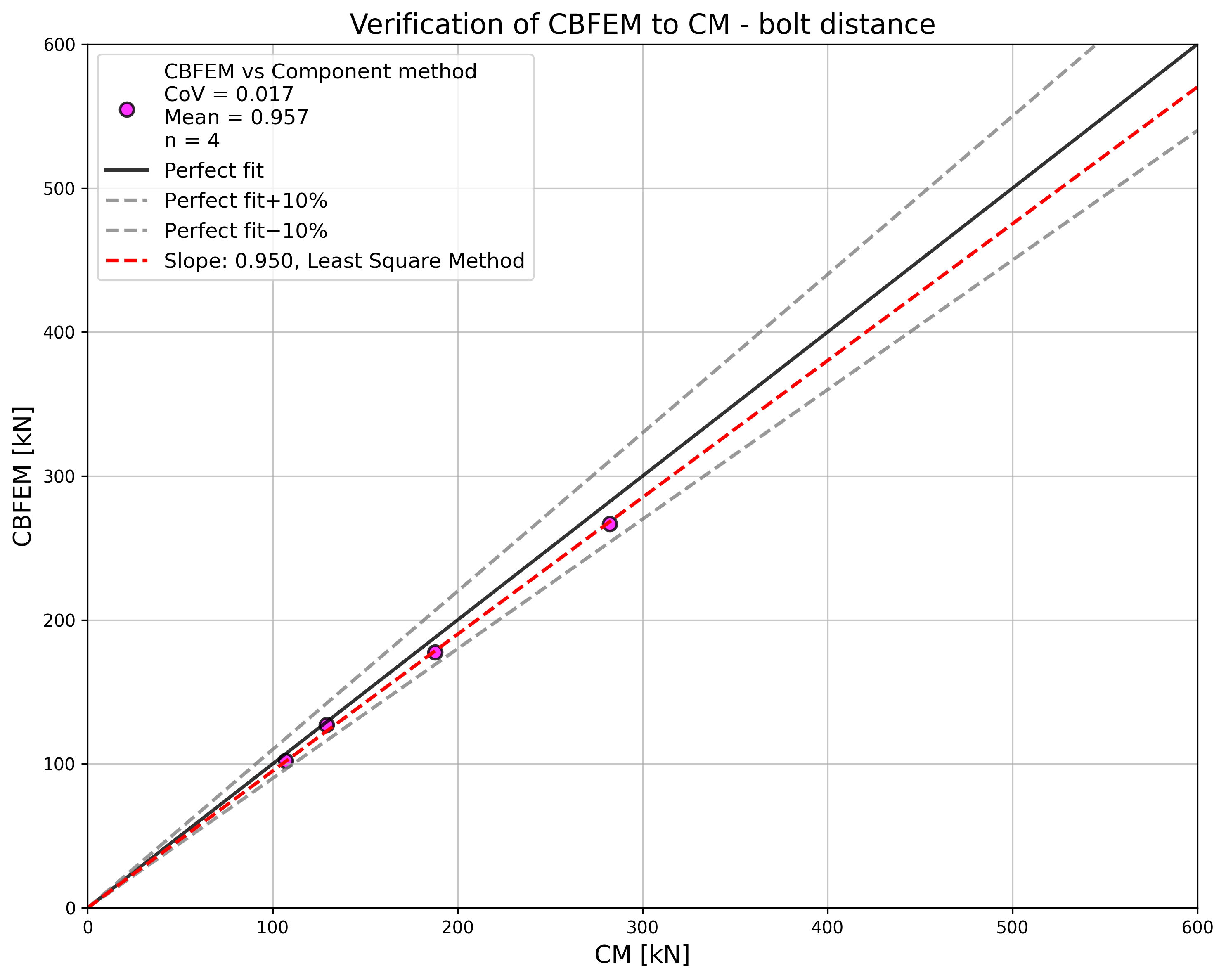
ในกรณีของระยะห่างสลักเกลียว ผลลัพธ์ของ CBFEM และ CM แสดงความสอดคล้องที่ดีโดยทั่วไป ดูรูปที่ 5.1.8 เมื่อระยะห่างสลักเกลียวเพิ่มขึ้น CBFEM ให้ความต้านทานสูงกว่า CM เล็กน้อย ด้วยเหตุนี้จึงแสดงผลลัพธ์ของ RM ด้วย RM ให้ความต้านทานสูงสุดในทุกกรณี
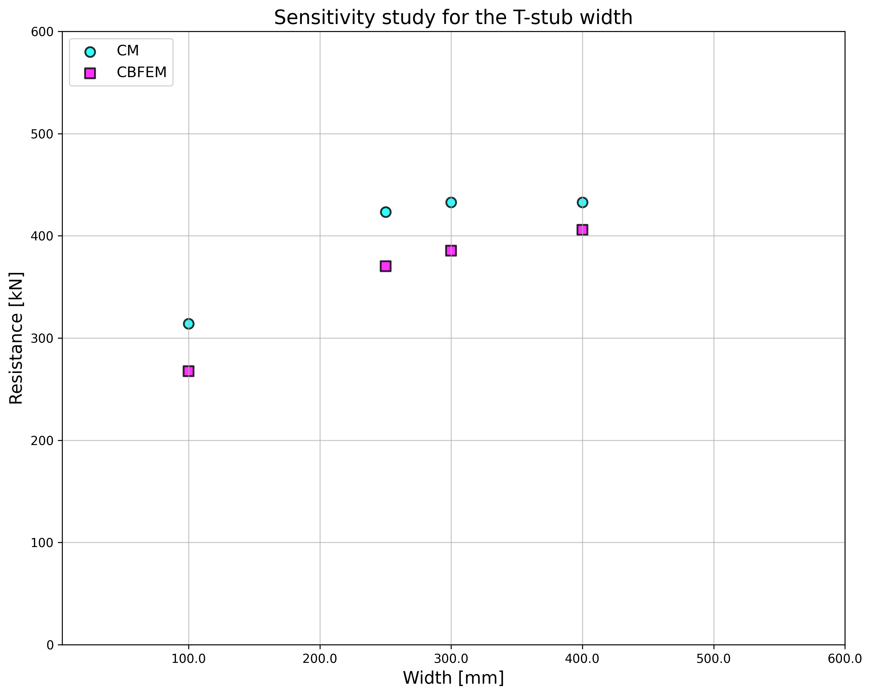
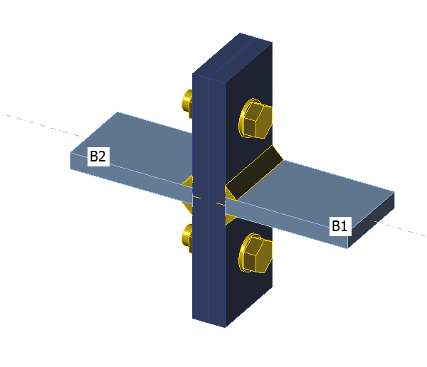
ในการศึกษาความกว้างของ T-stub CBFEM แสดงความต้านทานสูงกว่า CM เมื่อความกว้างเพิ่มขึ้น ผลลัพธ์ของ RM ได้รับการจัดทำขึ้น ซึ่งให้ความต้านทานสูงสุดในทุกกรณีอีกครั้ง ดูรูปที่ 5.1.9
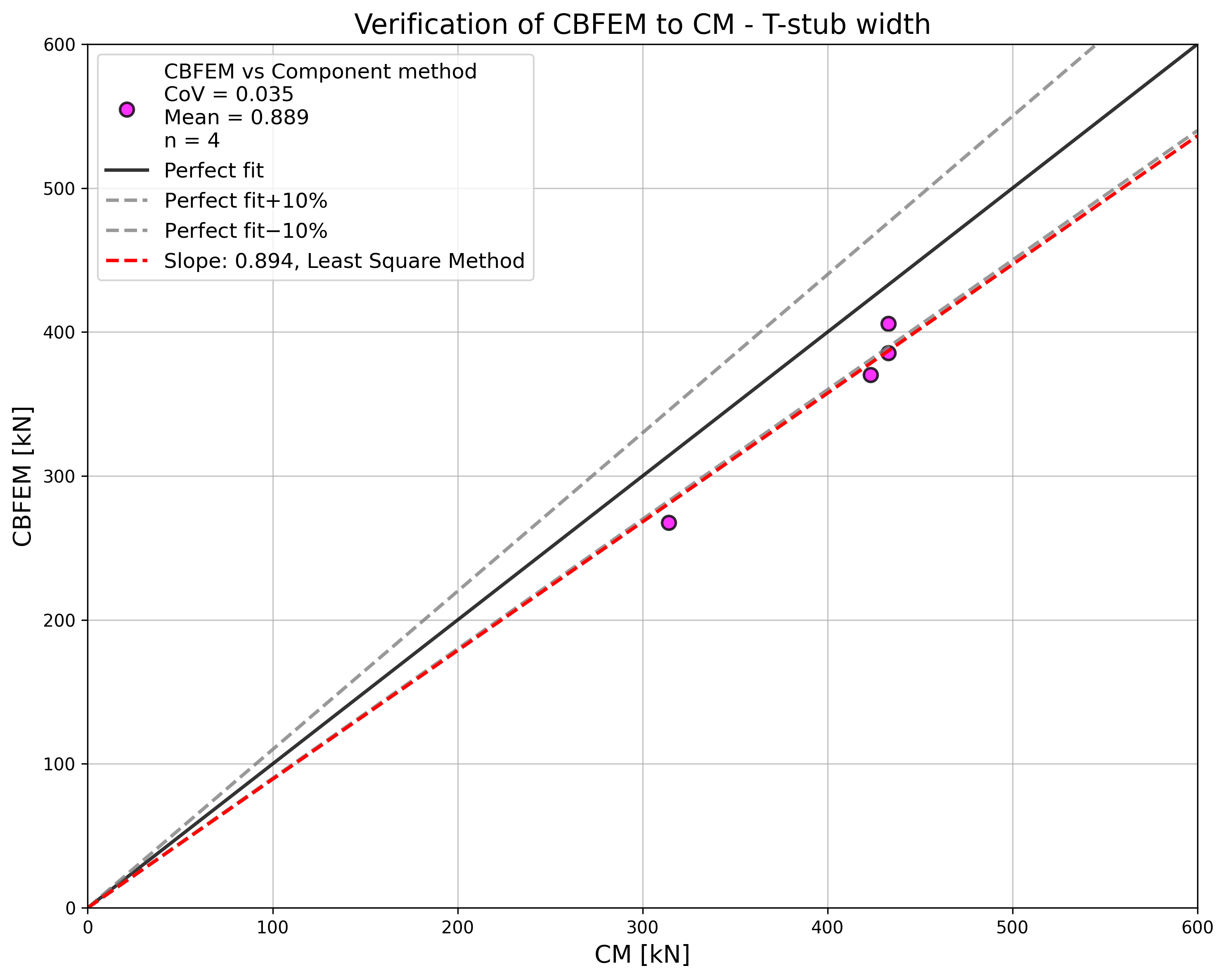
เพื่อแสดงการทำนายของแบบจำลอง CBFEM ผลลัพธ์ของการศึกษาถูกสรุปในกราฟที่เปรียบเทียบความต้านทานโดย CBFEM และ CM ดูรูปที่ 5.1.10 ผลลัพธ์แสดงให้เห็นว่าความแตกต่างระหว่างสองวิธีการคำนวณส่วนใหญ่อยู่ที่ไม่เกิน 10 % ในกรณีที่ CBFEM/CM > 1,1 ความถูกต้องของ CBFEM ได้รับการตรวจสอบโดยผลลัพธ์ของ RM ซึ่งให้ความต้านทานสูงสุดในทุกกรณีที่เลือก
ตัวอย่าง Benchmark
ข้อมูลนำเข้า
T-stub ดูรูปที่ 5.1.11
- เหล็ก S235
- ความหนาปีก tf = 20 mm
- ความหนาเอว tw = 20 mm
- ความกว้างปีก bf = 300 mm
- ความยาว b = 100 mm
- รอยเชื่อมตะเข็บคู่ aw = 10 mm
สลักเกลียว
- 2 × M24 8.8
- ระยะห่างของสลักเกลียว w = 165 mm
การตั้งค่ามาตรฐาน – แบบจำลองและ Mesh
- จำนวนองค์ประกอบบนชิ้นส่วนหรือปีกที่ใหญ่ที่สุด 16
ผลลัพธ์
- ความต้านทานการออกแบบรับแรงดึง FT,Rd = 164 kN
- โหมดการวิบัติ – การครากเต็มที่ของปีกที่ความเครียดสูงสุด 5 %
- อัตราการใช้งานของสลักเกลียว 86,4 %
- อัตราการใช้งานของรอยเชื่อม 45,7 %
เอกสารอ้างอิง
EN 1993-1-5, Eurocode 3, Design of steel structures – Part 1-5: Plated Structural Elements, CEN, Brussels, 2005.
EN 1993-1-8, Eurocode 3, Design of steel structures – Part 1-8: Design of joints, CEN, Brussels, 2005.
Beg D., Zupančič E., Vayas I. On the rotation capacity of moment connections, Journal of Constructional Steel Research, 60 (3–5), 2004, 601–620.
Gödrich L., Wald F., Sokol Z. To Advanced modelling of end plate joints, Connection and Joints in Steel and Composite Structures, Rzeszow, 2013.
Gödrich L., Wald F., Kabeláč J., Kuříková M. Design finite element model of a bolted T-stub connection component, Journal of Constructional Steel Research. 2019, (157), 198-206.
Wu Z., Zhang S., Jiang S. Simulation of tensile bolts in finite element modelling of semi-rigid beam-to-column connections, International Journal of Steel Structures 12 (3), 2012, 339-350.
คำอธิบาย
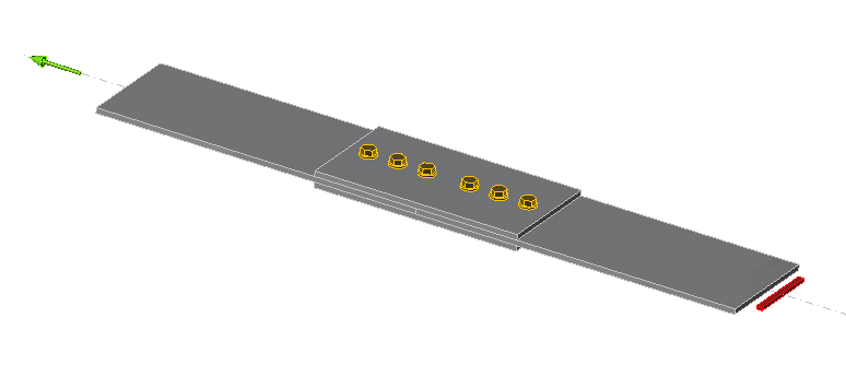
การศึกษานี้มุ่งเน้นไปที่การตรวจสอบวิธี Component-Based Finite Element (CBFEM) สำหรับความต้านทานของการเชื่อมต่อด้วยสลักเกลียวแบบต่อชนสมมาตรสองด้าน เทียบกับแบบจำลองเชิงวิเคราะห์ (AM)
แบบจำลองเชิงวิเคราะห์
ความต้านทานของสลักเกลียวในแรงเฉือนและความต้านทานของแผ่นเหล็กในการรับแรงกด ออกแบบตาม Tab. 3.4 ในหัวข้อ 3.6.1 ใน EN 1993-1-8:2005 สำหรับการเชื่อมต่อที่ยาว จะพิจารณาตัวประกอบลดค่าตาม cl. 3.8 และคำนึงถึงความต้านทานการออกแบบของชิ้นส่วนที่เชื่อมต่อพร้อมการลดค่าสำหรับรูตัวยึดตาม cl 3.10
การตรวจสอบความต้านทาน
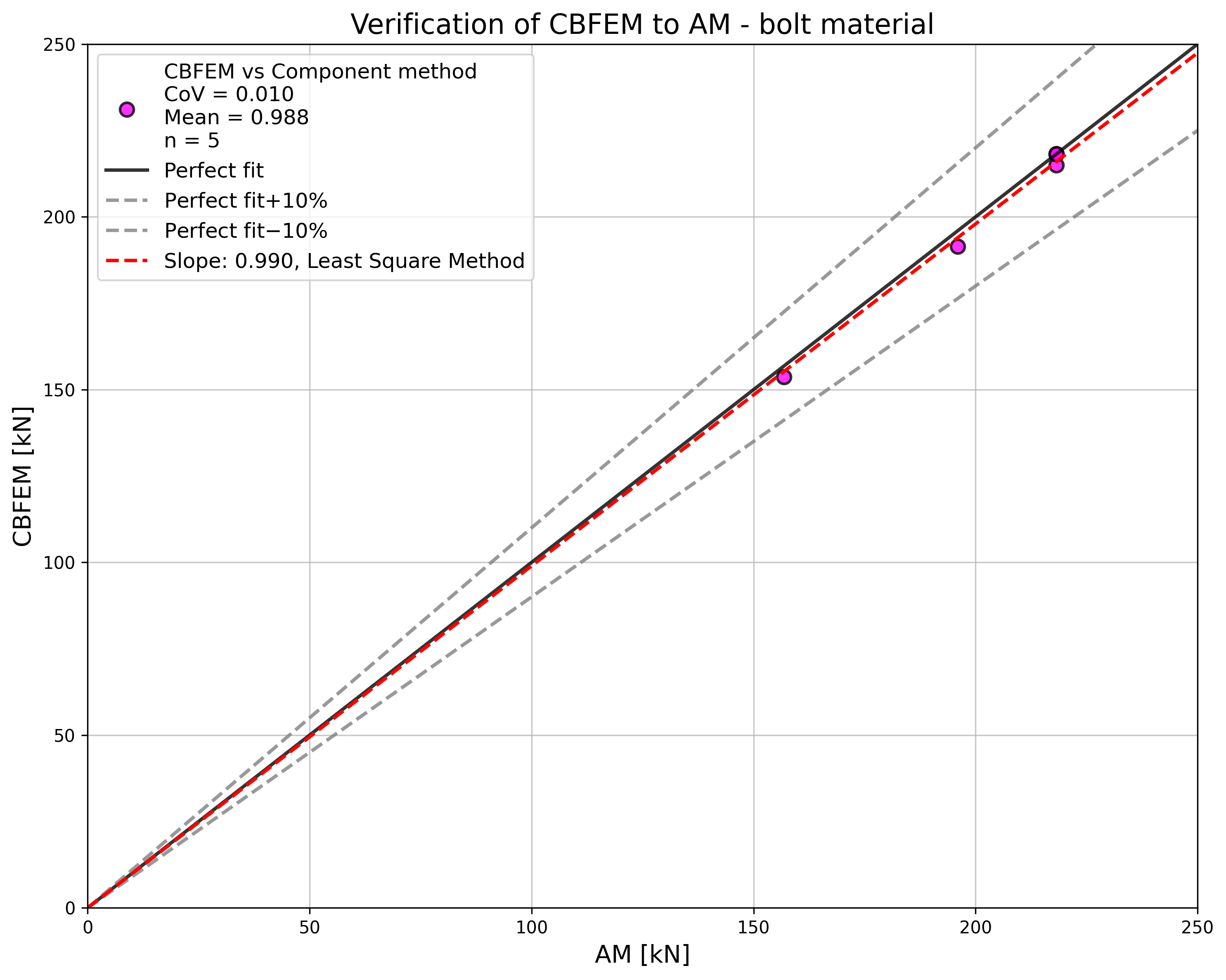
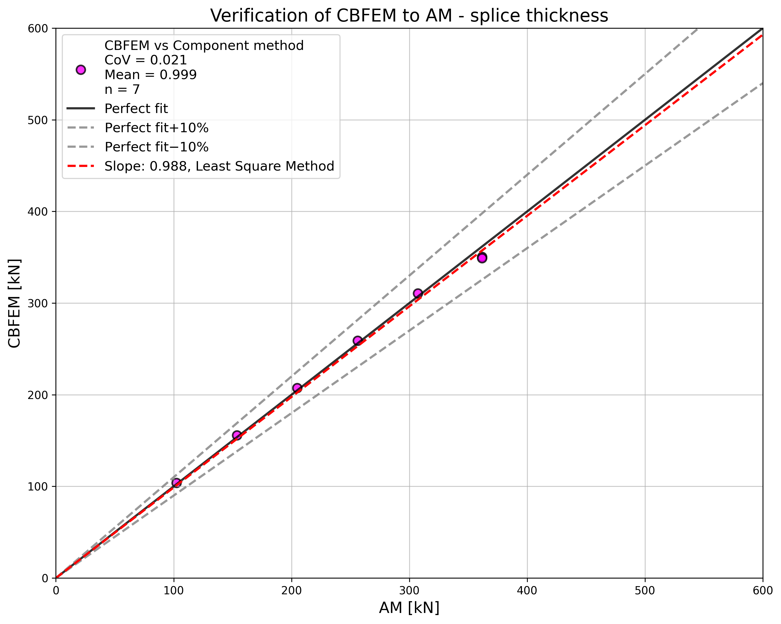
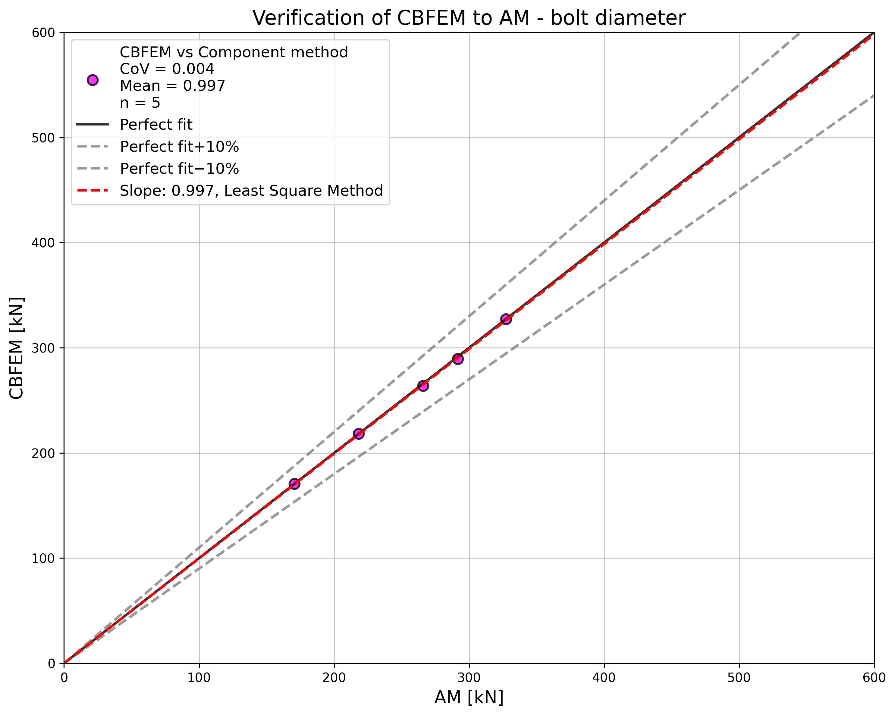
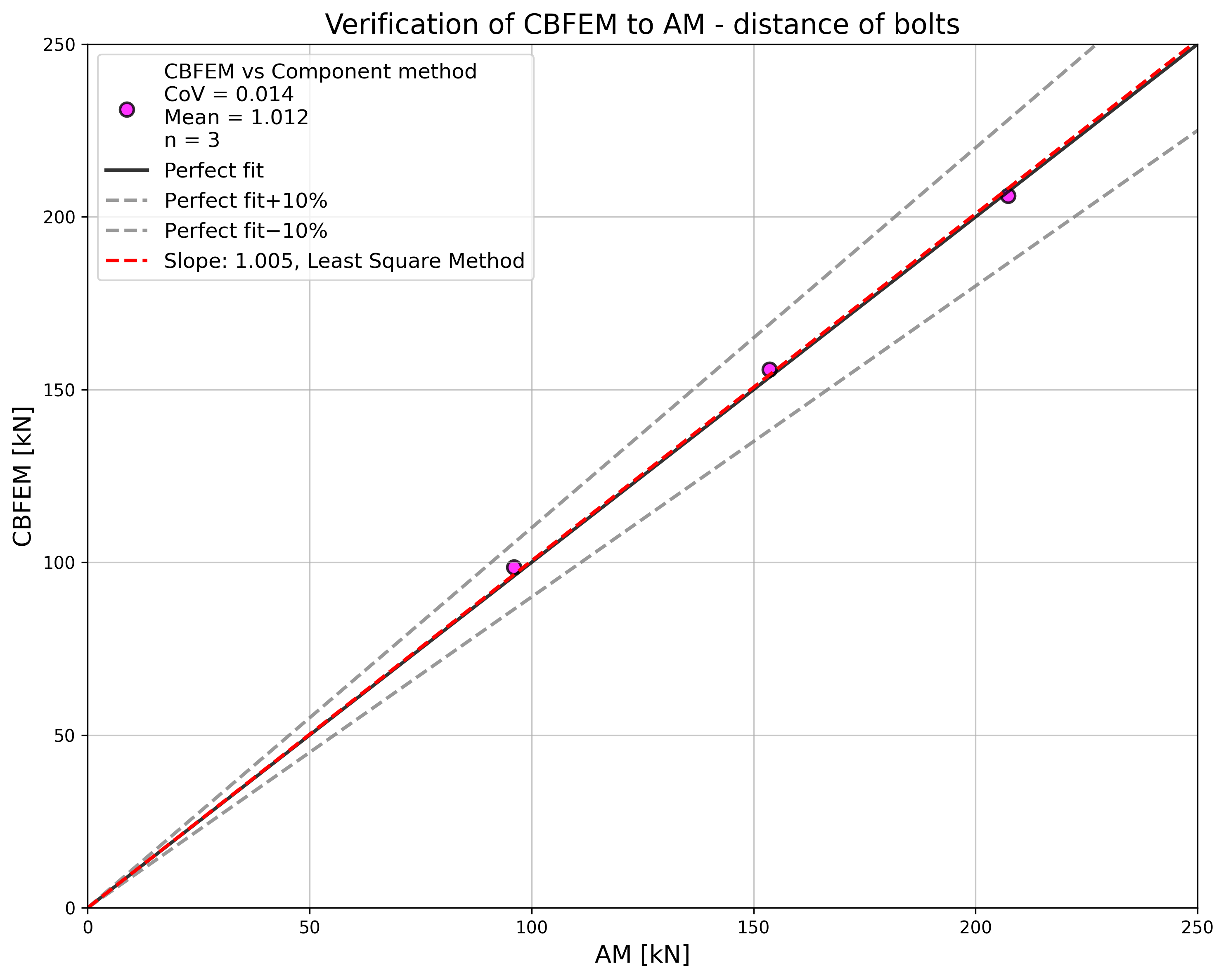
ค่าความต้านทานการออกแบบที่คำนวณโดย CBFEM ถูกเปรียบเทียบกับผลลัพธ์ของแบบจำลองเชิงวิเคราะห์ (AM) ผลลัพธ์สรุปไว้ใน Tab. 5.2.1 พารามิเตอร์ที่ใช้ได้แก่ วัสดุสลักเกลียว ความหนาของแผ่นต่อชน เส้นผ่านศูนย์กลางสลักเกลียว และระยะห่างของสลักเกลียว ดังแสดงใน Figs. 5.2.1 ถึง 5.2.4
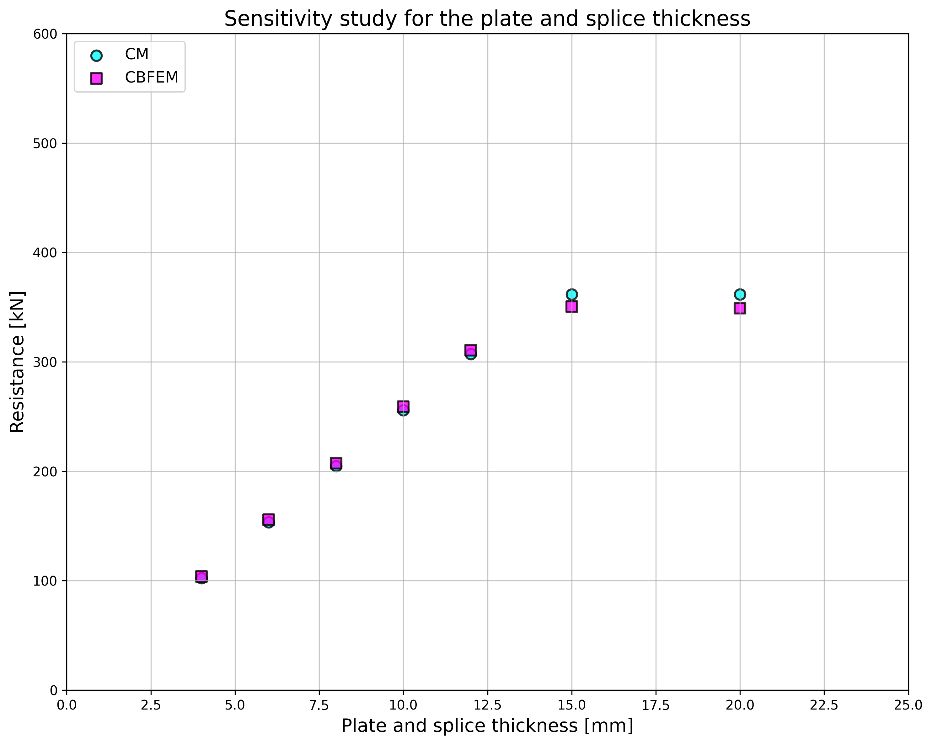
Tab. 5.2.1 การศึกษาความไวของความต้านทาน
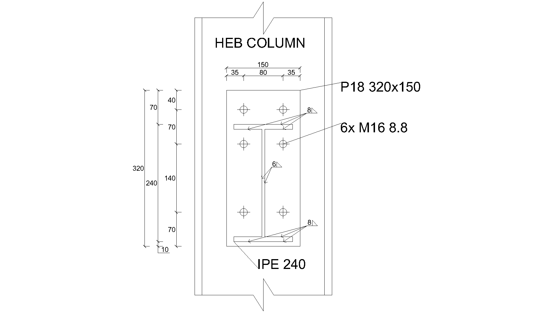
คำอธิบายจุดต่อ: แผ่นต่อชน 150/10 มม. สลักเกลียว 2×M20 ที่ระยะห่าง p =70, e1=50, แผ่น 2×150/6 มม. เหล็ก S235
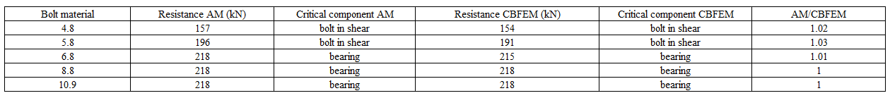
คำอธิบายจุดต่อ: ความสูงแผ่นต่อชน 200 มม. สลักเกลียว 3×M16 8.8 ที่ระยะห่าง p = 55 มม. e1 = 40 มม. แผ่น 2×200/t มม. เหล็ก S235
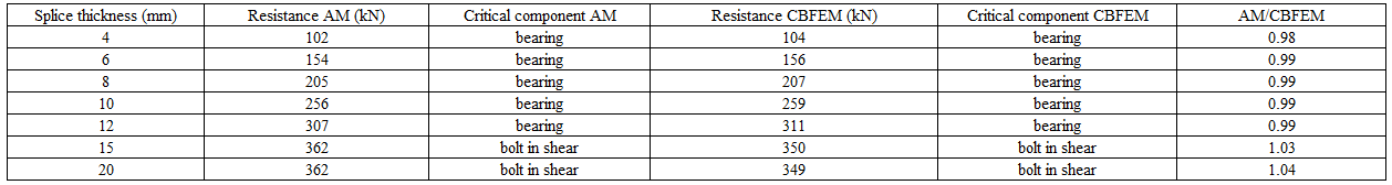
คำอธิบายจุดต่อ: แผ่นต่อชน 120/10 มม. สลักเกลียว 2×MX 8.8 แผ่น 2×120/10 มม. เหล็ก S235

คำอธิบายจุดต่อ: แผ่นต่อชน 200/6 มม. สลักเกลียว 3×M16 8.8 แผ่น 2×200/6 มม. เหล็ก S235

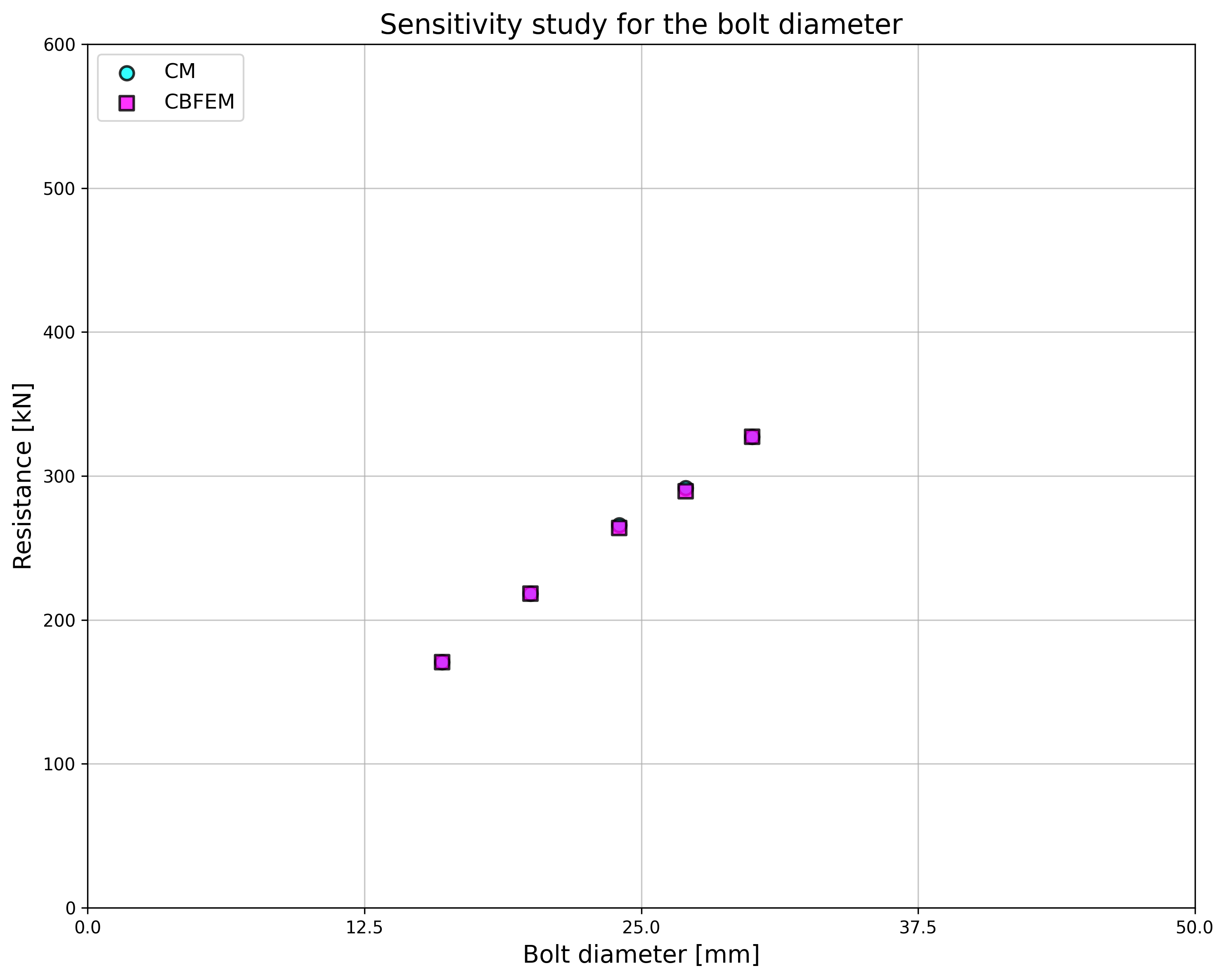
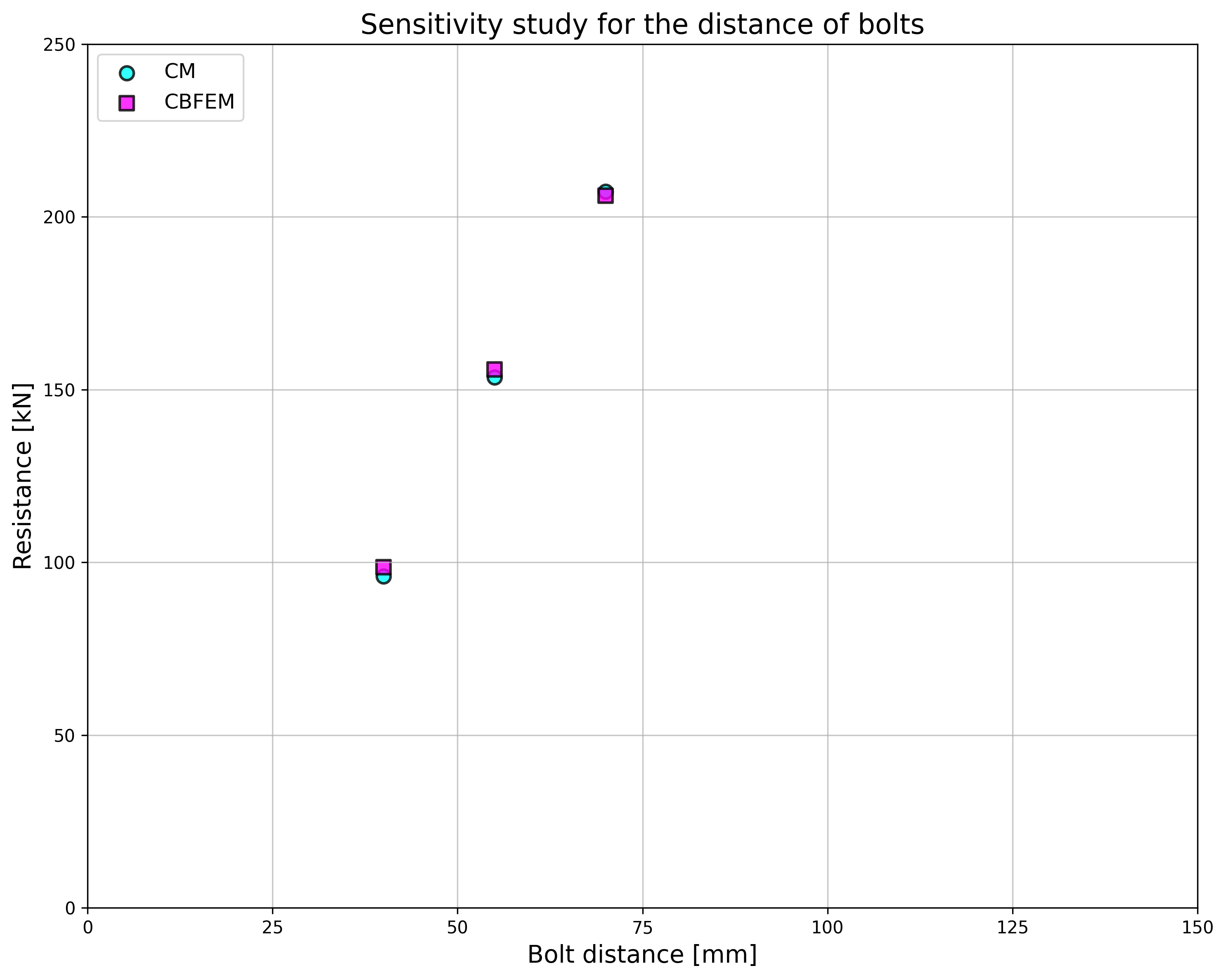
ผลลัพธ์ของการศึกษาความไวสรุปไว้ในกราฟใน Fig. 5.2.5 ผลลัพธ์แสดงให้เห็นว่าความแตกต่างระหว่างวิธีการคำนวณทั้งสองอยู่ต่ำกว่า 5 % โดยทั่วไปแบบจำลองเชิงวิเคราะห์ให้ค่าความต้านทานที่สูงกว่า
ตัวอย่าง Benchmark
ข้อมูลนำเข้า
ชิ้นส่วนที่เชื่อมต่อ
- เหล็ก S235
- แผ่นต่อชน 200/10 มม.
ตัวเชื่อมต่อ
สลักเกลียว
- 3 × M16 8.8
- ระยะห่าง e1 = 40 มม., p = 55 มม.
2 x แผ่นต่อชน
- เหล็ก S235
- แผ่น 380×200×10
ผลลัพธ์
- ค่าการออกแบบความต้านทาน FRd = 258 kN
- ตัวควบคุมคือการรับแรงกดของแผ่นต่อชนที่เชื่อมต่อ
คำอธิบาย
แบบจำลองวิธี Component-based finite element method (CBFEM) ของจุดต่อคานกับเสาได้รับการตรวจสอบโดยใช้วิธี Component method (CM) แผ่นปลายแบบขยายที่มีสามแถวสลักเกลียวเชื่อมต่อกับแผ่นเอวเสาและรับโมเมนต์ดัด ดังแสดงในรูปที่ 5.3.1
แบบจำลองเชิงวิเคราะห์
องค์ประกอบสามส่วนที่ควบคุมพฤติกรรม ได้แก่ แผ่นปลายในการดัด ปีกคานในแรงดึงและแรงอัด และแผ่นเอวเสาในการดัด แผ่นปลายและปีกคานในแรงดึงและแรงอัดได้รับการออกแบบตาม EN 1993-1-8:2005 พฤติกรรมของแผ่นเอวเสาในการดัดได้รับการทำนายตาม (Steenhuis et al. 1998) ผลการทดลองของจุดต่อคานกับเสาแกนรอง เช่น (Lima et al. 2009) แสดงให้เห็นการทำนายที่ดีสำหรับจุดต่อประเภทนี้ที่รับแรงในระนาบของคานที่เชื่อมต่อ
โดยที่:
- คือความหนาของแผ่นเอวเสา
- คือกำลังคราก (yield strength) ของแผ่นเอวเสา
- คือตัวประกอบความปลอดภัยบางส่วนของเหล็ก
- คือตัวประกอบความปลอดภัยบางส่วนของเหล็ก
- จำนวนแถวสลักเกลียวในโซนแรงดึง
- เส้นผ่านศูนย์กลางแนวทแยงของหัวสลักเกลียว
- ระยะห่างแนวนอนระหว่างสลักเกลียว
- ระยะห่างแนวตั้งระหว่างสลักเกลียว
- แขนโมเมนต์ของจุดต่อ
- คือความต้านทานต่อแรงเฉือนแบบเจาะทะลุ
- คือความต้านทานต่อการรวมกันของแรงเจาะทะลุ แรงเฉือน และการดัด
แบบจำลองเชิงตัวเลข
การประเมินอ้างอิงจากความเครียดสูงสุดตามที่กำหนดใน EN 1993-1-5:2006 ที่ค่า 5 % ข้อมูลโดยละเอียดเกี่ยวกับแบบจำลอง CBFEM สรุปไว้ในบทที่ 3
การตรวจสอบความต้านทาน
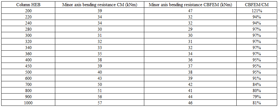
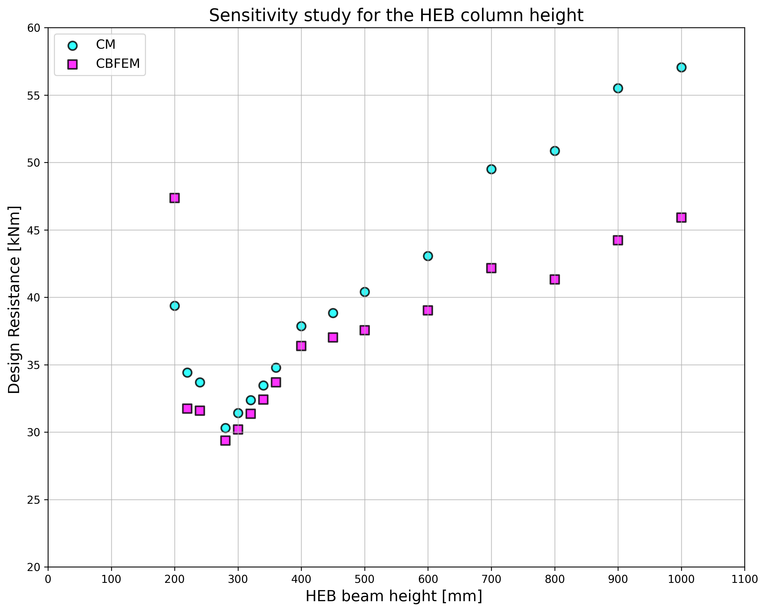
การศึกษาความไวของความต้านทานจุดต่อได้จัดทำขึ้นสำหรับหน้าตัดเสา รูปทรงเรขาคณิตของจุดต่อแสดงในรูปที่ 5.3.1 ใน Tab. 5.3.1 และในรูปที่ 5.3.3 สรุปผลการคำนวณในกรณีที่ขยายแผ่นปลาย P18 เทียบกับหน้าตัดเสา
Tab. 5.3.1 ผลการทำนายการเชื่อมต่อแผ่นปลายแกนรองสำหรับคานหลังคาต่างๆ
พฤติกรรมโดยรวม
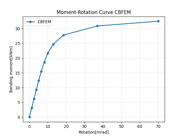
พฤติกรรมโดยรวมแสดงด้วยเส้นโค้งแรง-การเสียรูป คาน IPE 240 เชื่อมต่อกับเสา HEB 300 ด้วยสลักเกลียว M16 8.8 จำนวนหกตัว รูปทรงเรขาคณิตของแผ่นปลายแสดงในรูปที่ 5.3.1 และใน Tab. 5.3.1 การเปรียบเทียบผลลัพธ์ของทั้งสองวิธีแสดงในรูปที่ 5.3.4 และใน Tab. 5.3.2 ทั้งสองวิธีทำนายความต้านทานการออกแบบที่ใกล้เคียงกัน โดยทั่วไป CBFEM ให้ค่าความแข็งเริ่มต้นที่ต่ำกว่าเมื่อเทียบกับ CM
Tab. 5.3.2 คุณลักษณะหลักสำหรับพฤติกรรมโดยรวม
| CM | CBFEM | CM/CBFEM | ||
| ความแข็งเริ่มต้น | [kNm/rad] | 16130 | 2232 | 7.23 |
| ความต้านทานการออกแบบ | [kNm] | 31 | 30 | 1,03 |
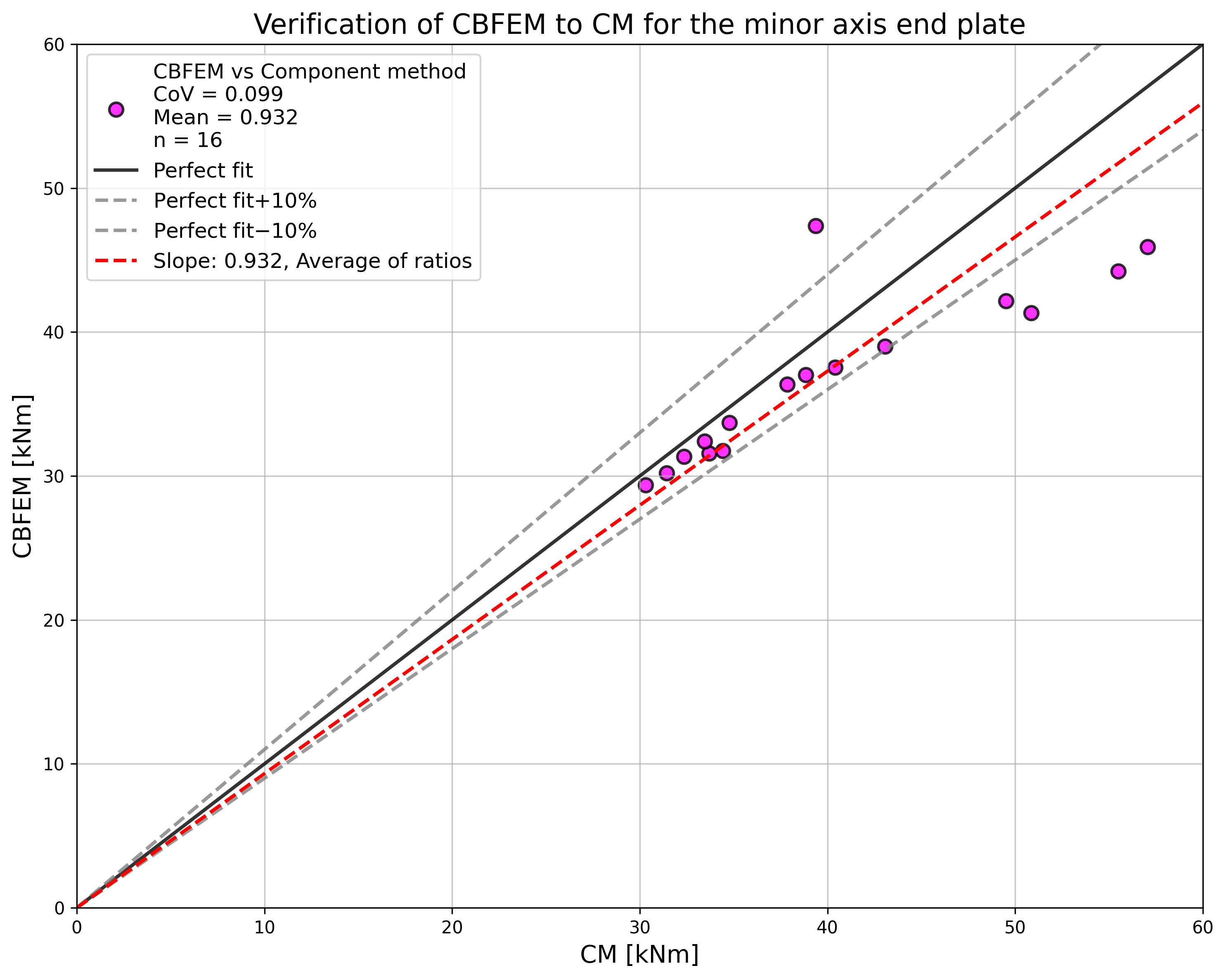
ผลการศึกษาสรุปในกราฟที่เปรียบเทียบความต้านทานโดย CBFEM และวิธี Component method ดังแสดงในรูปที่ 5.3.5 ผลลัพธ์แสดงให้เห็นว่าความแตกต่างระหว่างวิธีมีค่าสูงสุดถึง 14 % CBFEM ทำนายความต้านทานที่ต่ำกว่าในทุกกรณีเมื่อเทียบกับ CM ซึ่งอ้างอิงจากการทำให้ง่ายขึ้นใน (Steenhuis et al. 1998) ผลลัพธ์ที่คล้ายกันอาจพบได้ในงานของ (Wang and Wang, 2012)
ตัวอย่าง Benchmark
กรณี Benchmark จัดทำขึ้นสำหรับการเชื่อมต่อแผ่นปลายแกนรองตามรูปที่ 5.3.1 โดยมีรูปทรงเรขาคณิตที่ปรับเปลี่ยนดังสรุปด้านล่าง
ข้อมูลนำเข้า
- เหล็ก S235
- เสา HEB 300
- คาน IPE 240
- สลักเกลียว 6×M16 8.8
- ความหนารอยเชื่อม 5 mm
- ความหนาแผ่นปลาย tp = 18 mm
ผลลัพธ์
- ความต้านทานการออกแบบในการดัด MRd = 30 kNm
- องค์ประกอบควบคุม – แผ่นเอวเสาในการดัด
เอกสารอ้างอิง
EN 1993-1-5, Eurocode 3, Design of steel structures – Part 1-5: Plated Structural Elements, CEN, Brussels, 2005.
Steenhuis M., Jaspart J. P., Gomes F., Leino T. Application of the component method to steel joints, in Control of the Semi-rigid Behaviour of Civil Engineering Structural Connections Conference, COST C1, Liege, Belgium, 1998, 125-143.
Wang Z., Wang T. Experiment and finite element analysis for the end plate minor axis connection of semi-rigid steel frames, Tumu Gongcheng Xuebao/China Civil Engineering Journal, 45 (8), 2012, 83-89.
คำอธิบาย
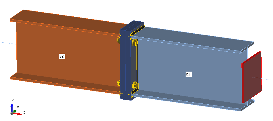
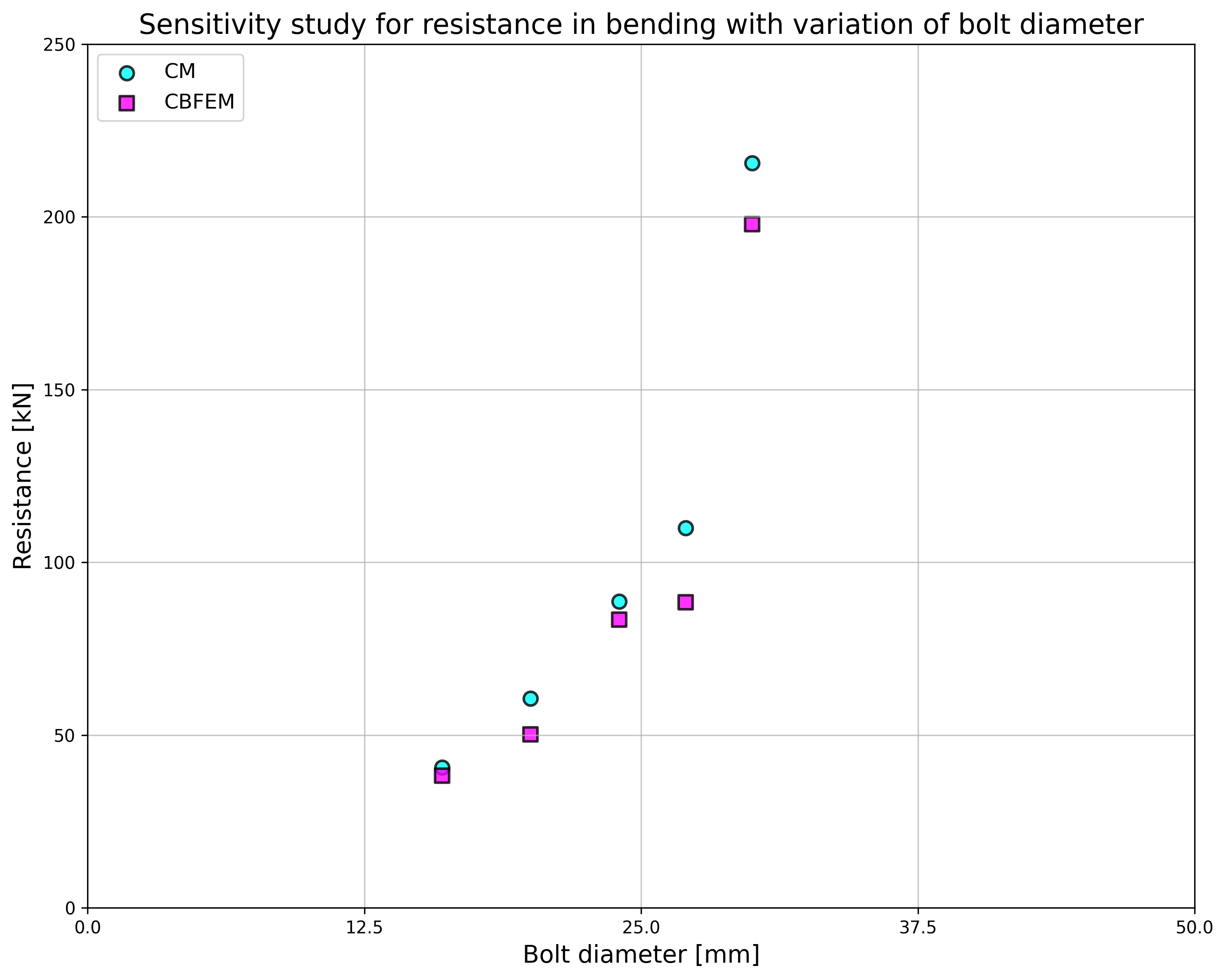
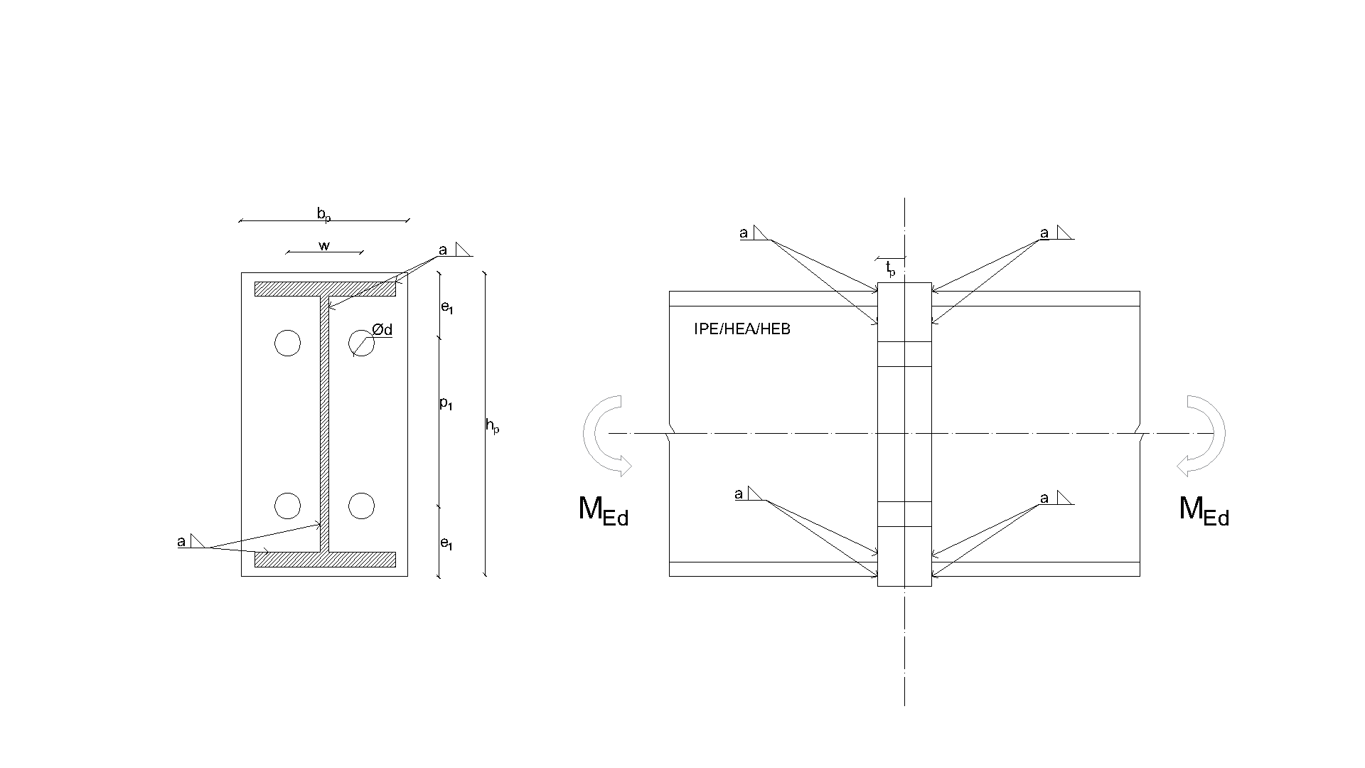
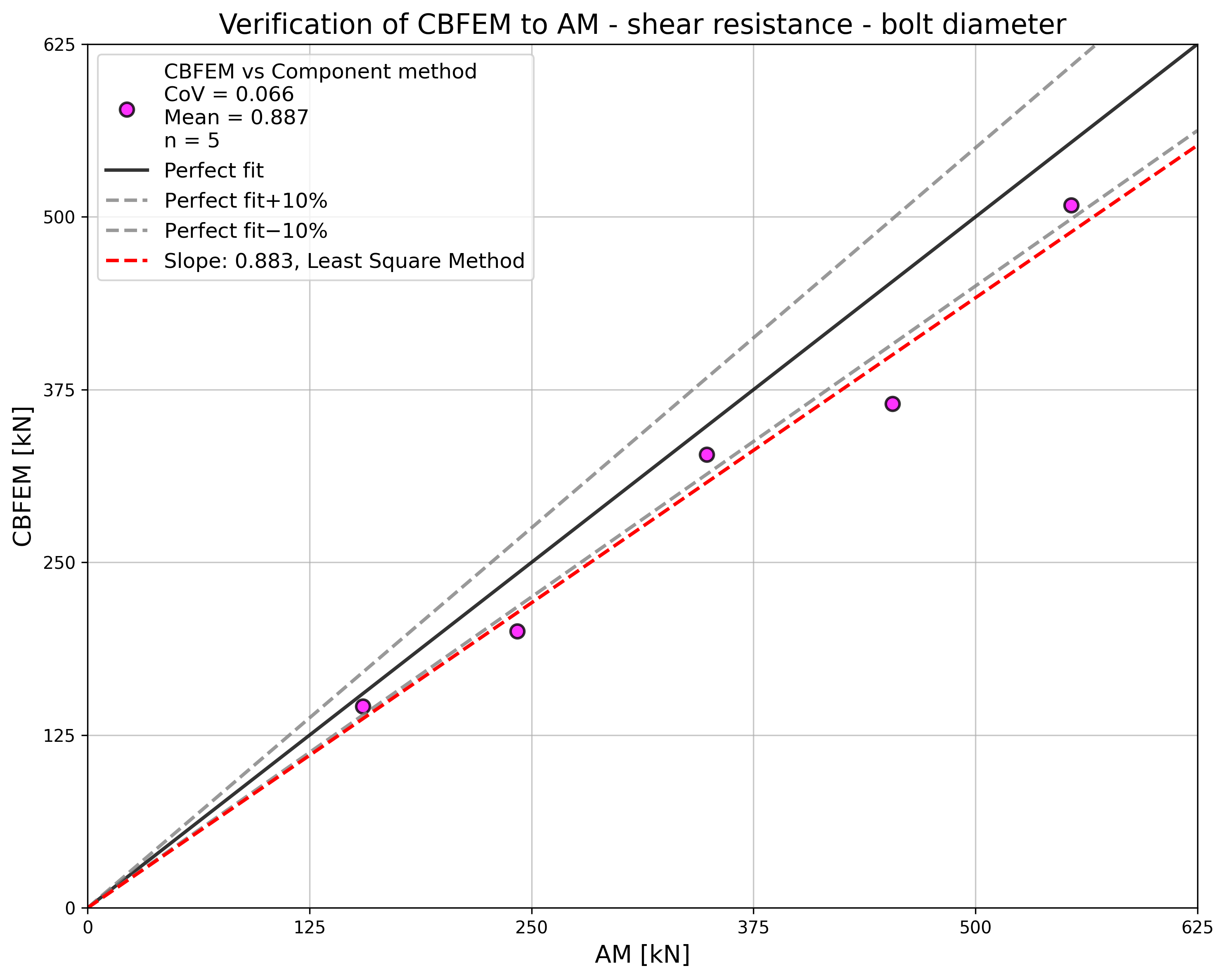
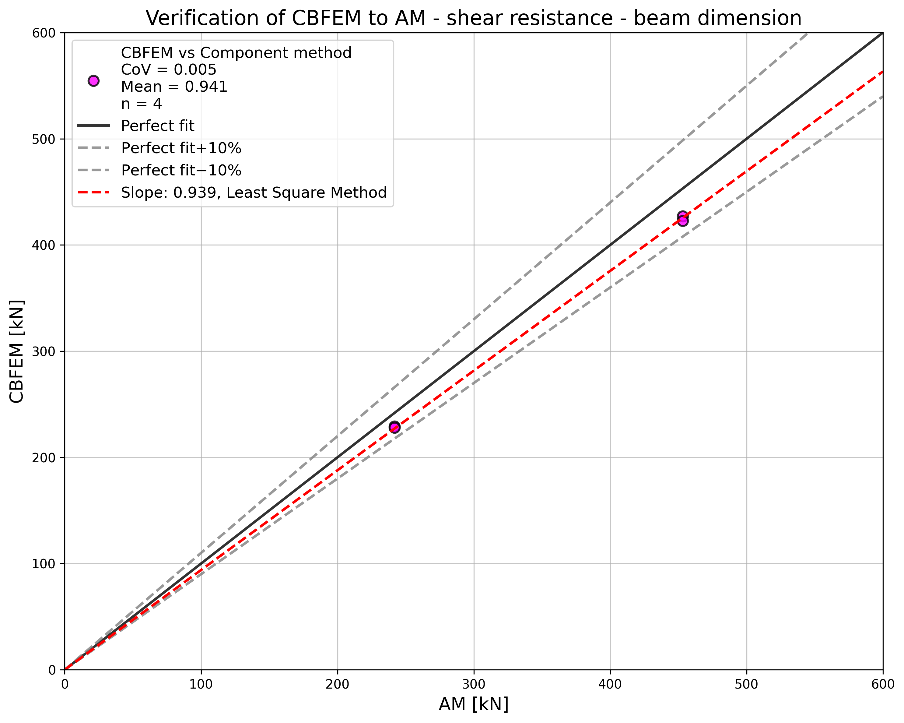
วัตถุประสงค์ของบทนี้คือการตรวจสอบวิธี Component-Based Finite Element (CBFEM) สำหรับปฏิสัมพันธ์ระหว่างแรงเฉือนและแรงดึงในสลักเกลียวเทียบกับแบบจำลองเชิงวิเคราะห์ (AM) โดยเลือกจุดต่อคานต่อคานที่มีแผ่นปลายและสลักเกลียวสองแถวสำหรับการตรวจสอบ ดังแสดงในรูปที่ 5.5.1 ความแข็งแกร่งในการดัดของจุดต่อมีค่าสูงเพียงพอที่จะจัดประเภทเป็นแบบแข็ง
แบบจำลองเชิงวิเคราะห์
ความต้านทานของสลักเกลียวในปฏิสัมพันธ์ระหว่างแรงเฉือนและแรงดึงออกแบบตามตารางที่ 3.4 ในบทที่ 3.6.1 ใน EN 1993-1-8:2005 โดยใช้ความสัมพันธ์แบบสองเส้นตรง รูปทรงเรขาคณิตและขนาดของแผ่นปลายของจุดต่อถูกเลือกเพื่อจำกัดค่าการออกแบบความต้านทานของจุดต่อโดยการวิบัติของสลักเกลียว ค่าการออกแบบความต้านทานของ T-stub สมมูลในแรงดึงถูกจำลองตามตารางที่ 6.2 ในบทที่ 6.2.4 ใน EN 1993‑1‑8:2005
การตรวจสอบความต้านทาน
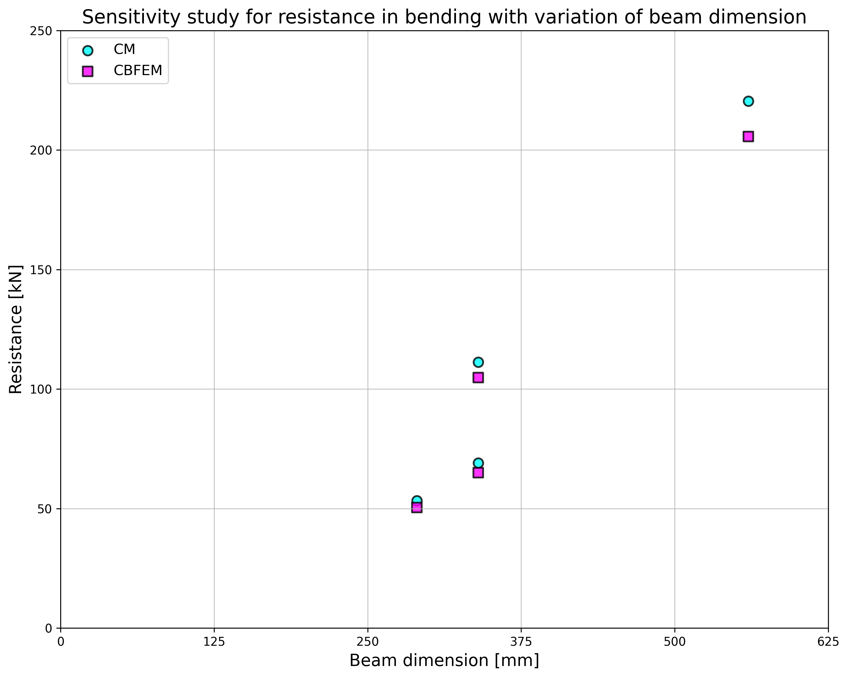
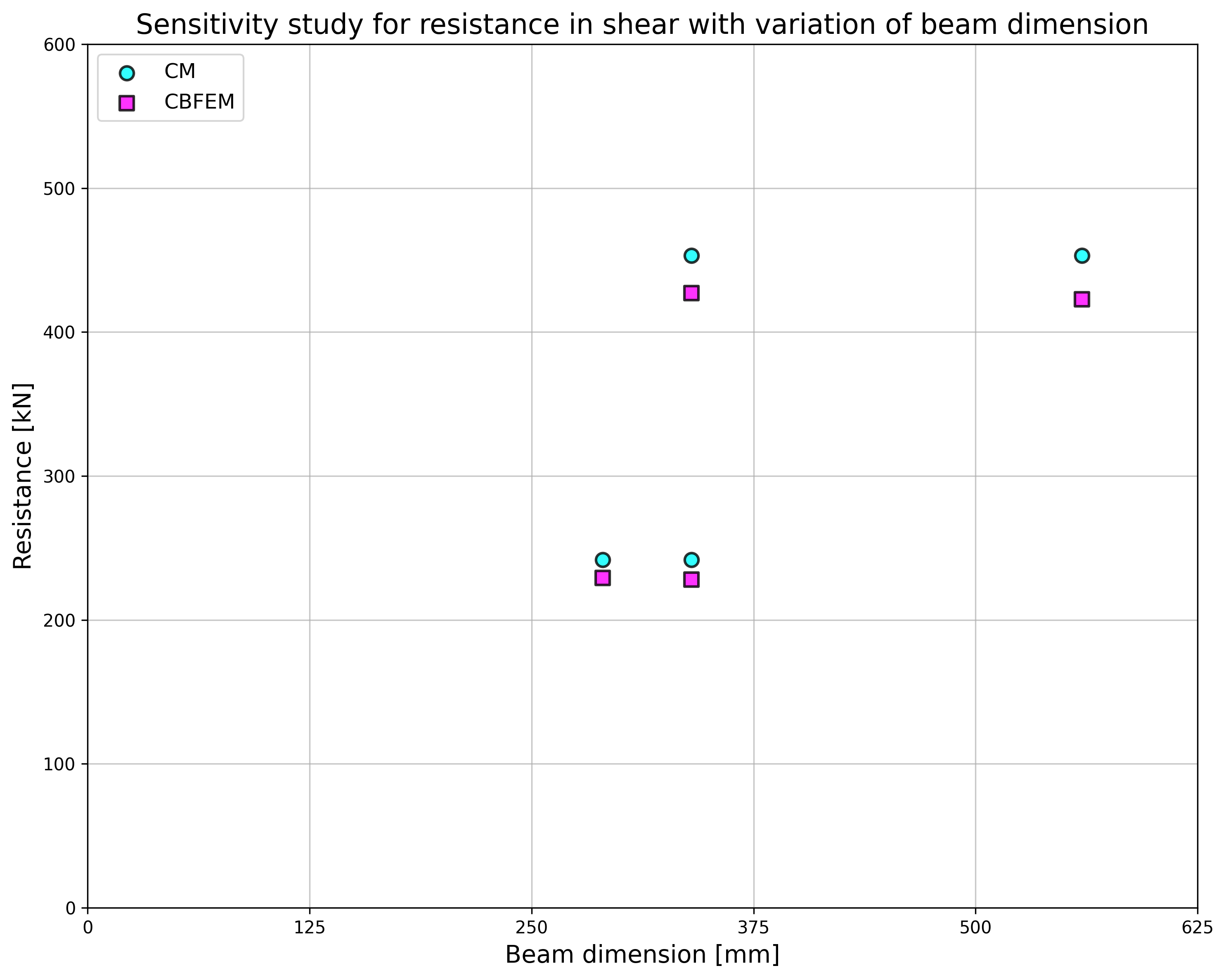
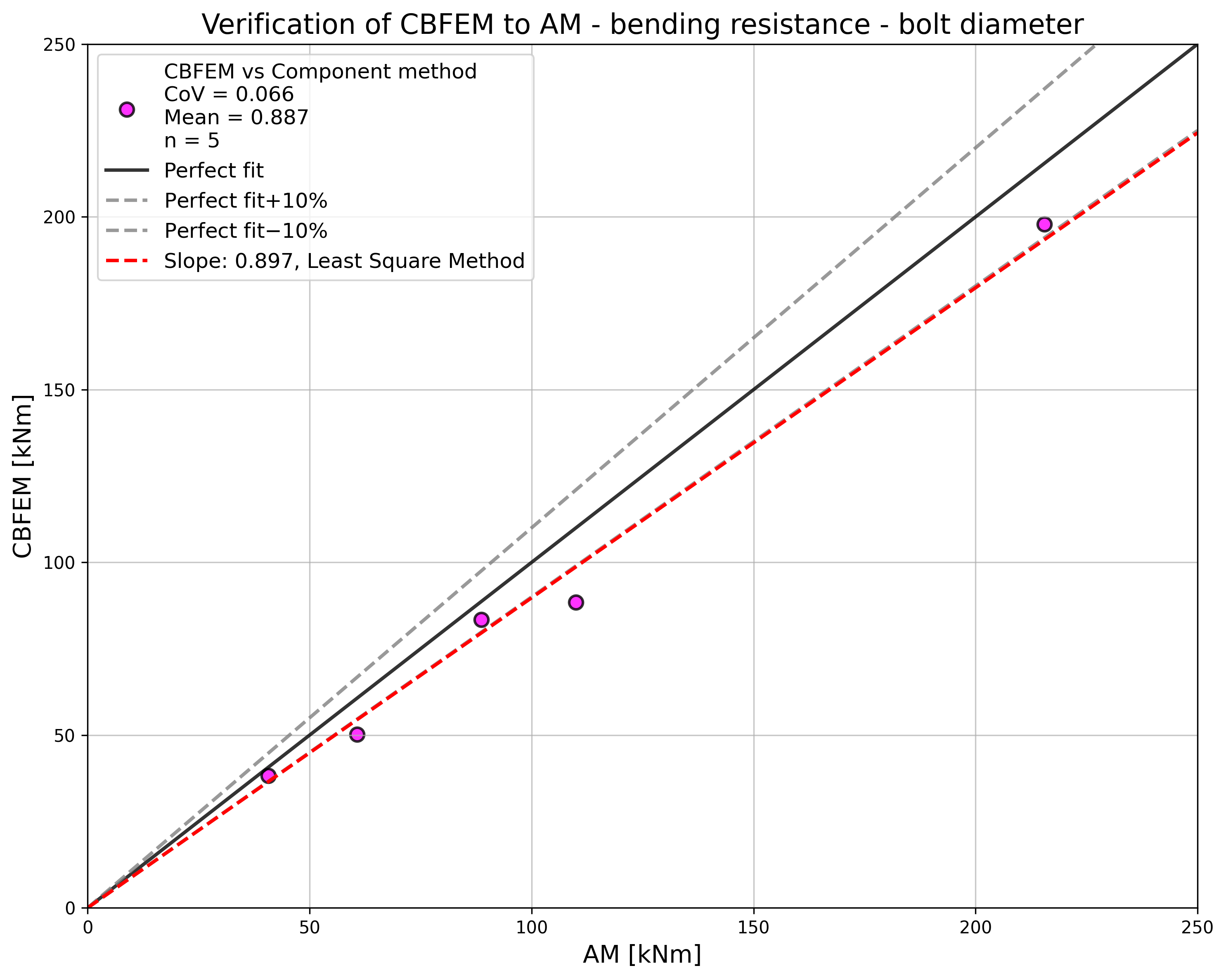
พารามิเตอร์ของแบบจำลองได้แก่ เส้นผ่านศูนย์กลางสลักเกลียวและขนาดคาน ดังแสดงในรูปที่ 5.5.2 ถึง 5.5.5 ขนาดของแผ่นปลายและระยะห่างของสลักเกลียวถูกปรับเพื่อจำกัดความต้านทานของจุดต่อโดยการวิบัติของสลักเกลียว ความต้านทานแรงเฉือนและการดัดของจุดต่อถูกเปรียบเทียบที่การรับแรงเมื่อสลักเกลียววิบัติ ผลลัพธ์สรุปไว้ในตารางที่ 5.5.1 และ 5.5.2
ตารางที่ 5.5.1 การศึกษาความไวสำหรับความต้านทานโดยการเปลี่ยนแปลงเส้นผ่านศูนย์กลางสลักเกลียว
| พารามิเตอร์ | AM | CBFEM | AM/CBFEM | |||||
| คาน; แผ่นปลาย | เส้นผ่านศูนย์กลาง | ระยะห่าง | MRd [kNm] | VRd [kN] | MRd [kNm] | VRd [kN] | MRd | VRd |
| IPE270; tp = 30mm; 150×310mm | M16/8.8 | e1 = 60 mm; p1 = 190 mm; w = 90 mm | 41 | 155 | 38 | 146 | 1,06 | 1,06 |
| M20/8.8 | e1 = 70 mm; p1 = 170 mm; w = 90 mm | 61 | 242 | 50 | 200 | 1,21 | 1,21 | |
| HEA300; tp = 40mm; 300×330mm | M24/8.8 | e1 = 85 mm; p1 = 160 mm; w = 150 mm | 89 | 349 | 83 | 328 | 1,06 | 1,06 |
| M27/8.8 | e1 = 95 mm; p1 = 140 mm; w = 150 mm | 110 | 453 | 89 | 365 | 1,24 | 1,24 | |
| HEA500; tp = 40mm; 330×520mm | M30/8.8 | e1 = 160 mm; p1 = 200 mm; w = 150 mm | 216 | 554 | 198 | 509 | 1,09 | 1,09 |
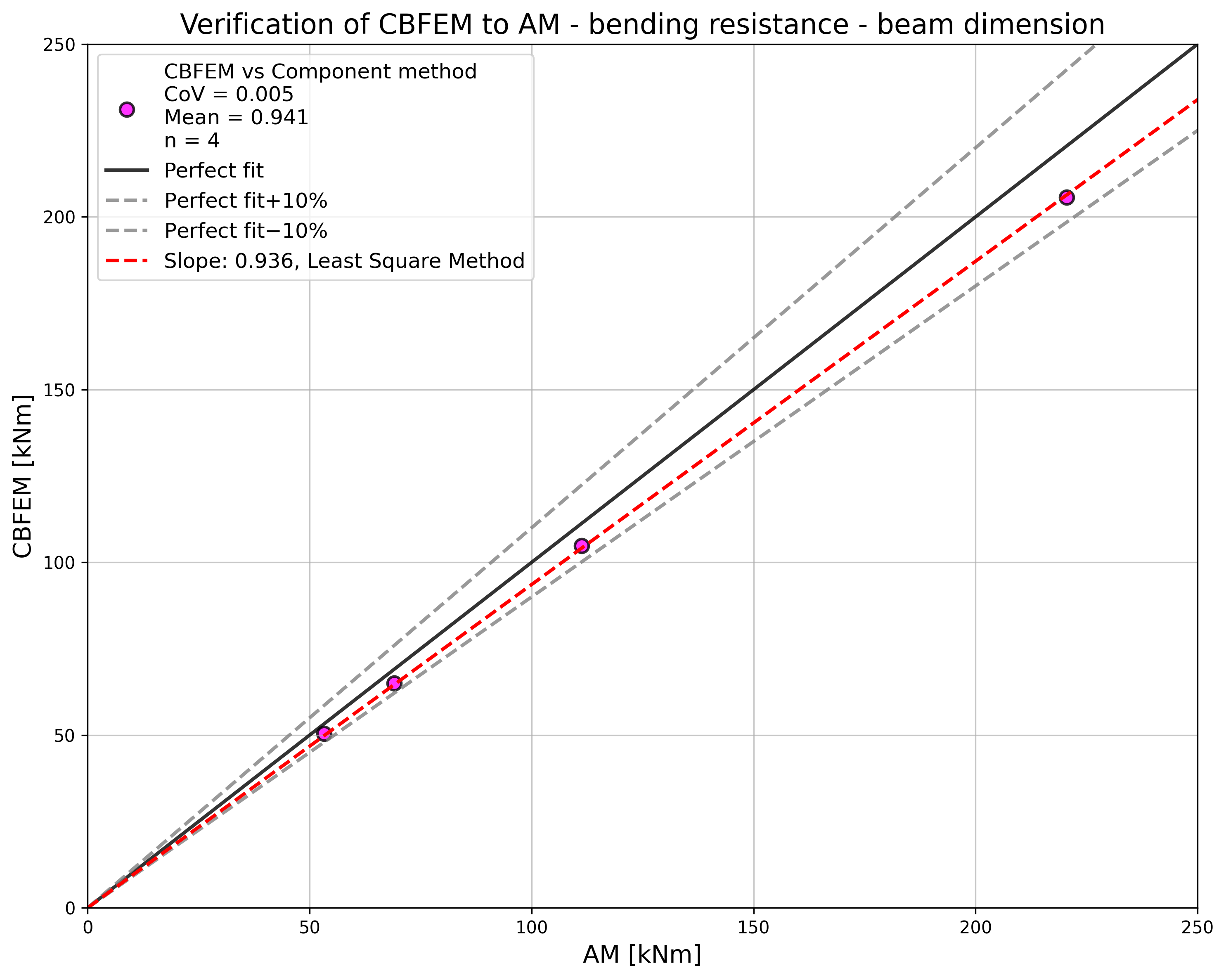
ตารางที่ 5.5.2 การศึกษาความไวสำหรับความต้านทานโดยการเปลี่ยนแปลงขนาดคาน
| พารามิเตอร์ | AM | AM | CBFEM | CBFEM | AM/CBFEM | AM/CBFEM | ||
| คาน; แผ่น Fin | เส้นผ่านศูนย์กลาง | ระยะห่าง | MRd [kNm] | VRd [kN] | MRd [kNm] | VRd [kN] | MRd | VRd |
| HEA260; tp = 25mm; 260×290mm | M20/8.8 | e1 = 75 mm; p1 = 140 mm; w = 130 mm | 53 | 242 | 50 | 229 | 1,06 | 1,06 |
| IPE300; tp = 30mm; 150×340mm | M20/8.8 | e1 = 70 mm; p1 = 200 mm; w = 90 mm | 69 | 242 | 65 | 228 | 1,06 | 1,06 |
| HEB300; tp = 40mm; 300×340mm | M27/8.8 | e1 = 100 mm; p1 = 140 mm; w = 150 mm | 111 | 453 | 105 | 427 | 1,06 | 1,06 |
| IPE500; tp = 45mm; 220×560mm | M27/8.8 | e1 = 105 mm; p1 = 350 mm; w = 120 mm | 220 | 453 | 206 | 423 | 1,07 | 1,07 |
ผลลัพธ์ของการศึกษาความไวสรุปไว้ในกราฟในรูปที่ 5.5.6 และ 5.5.7 ผลลัพธ์แสดงให้เห็นว่าความแตกต่างระหว่างวิธีการคำนวณทั้งสองต่ำกว่า 10 % โดยทั่วไปแบบจำลองเชิงวิเคราะห์ให้ค่าความต้านทานที่สูงกว่า
ตัวอย่าง Benchmark
ข้อมูลนำเข้า
ชิ้นส่วนที่เชื่อมต่อ
- เหล็ก S355
- คาน HEA300
- ความหนาแผ่นปลาย tp = 40 mm
- ขนาดแผ่นปลาย 300 × 330 mm
สลักเกลียว
- 4 × M24 8.8
- ระยะห่าง e1 = 85 mm; p1 = 160 mm; w1 = 75 mm; w = 150 mm
ผลลัพธ์
- ค่าการออกแบบความต้านทานในการดัด MRd = 93 kNm
- ค่าการออกแบบความต้านทานแรงเฉือน VRd = 291 kN
- รูปแบบการวิบัติคือการวิบัติของสลักเกลียวในปฏิสัมพันธ์ระหว่างแรงเฉือนและแรงดึง
คำอธิบาย
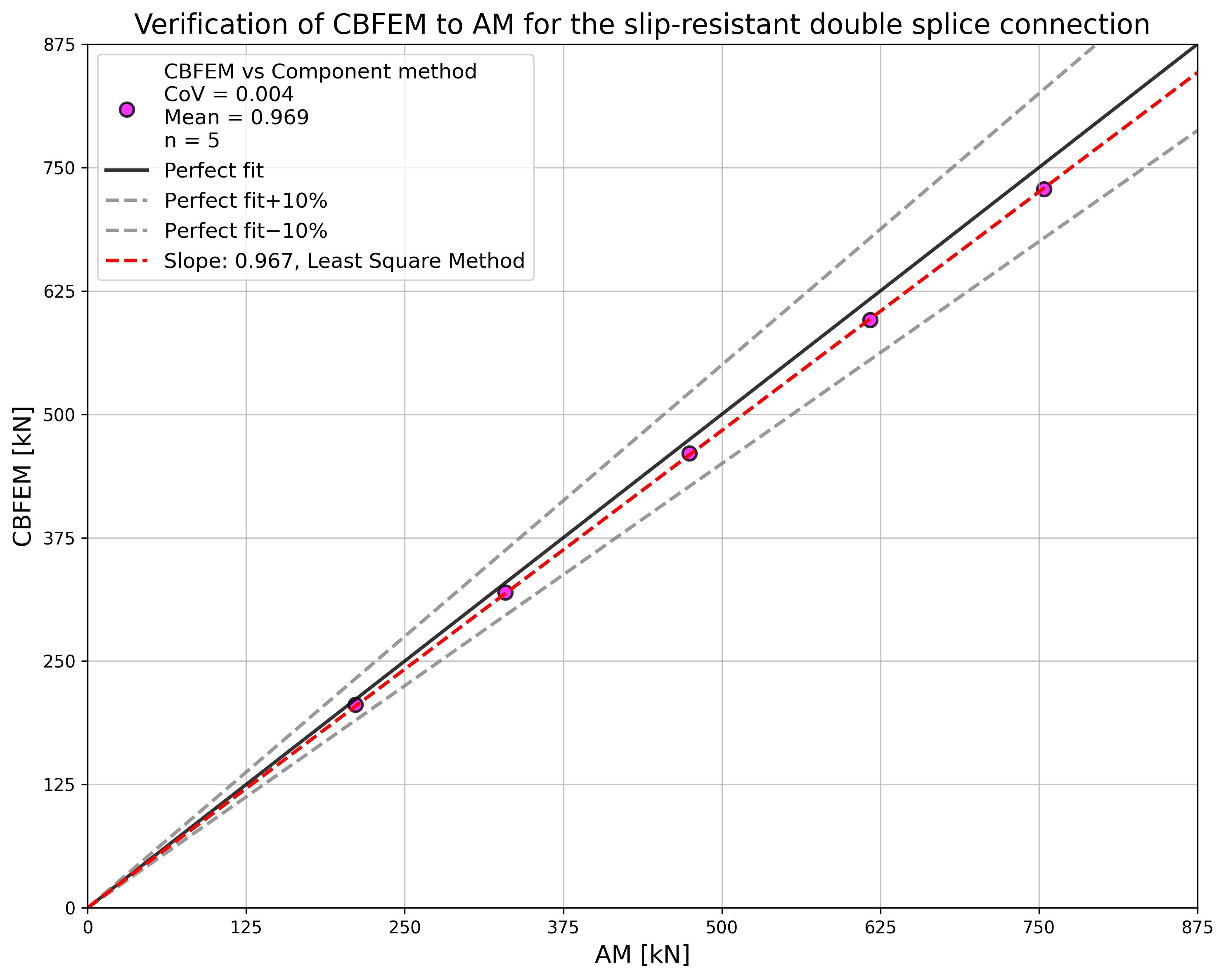
การศึกษานี้มุ่งเน้นไปที่การตรวจสอบความถูกต้องของวิธี Component-Based Finite Element (CBFEM) สำหรับความต้านทานของการเชื่อมต่อแบบต้านทานการลื่นแบบต่อสองด้านสมมาตร เทียบกับแบบจำลองเชิงวิเคราะห์ (AM)
แบบจำลองเชิงวิเคราะห์
ความต้านทานการลื่นของสลักเกลียวอัดแรงได้รับการออกแบบตามบทที่ 3.9.1 ใน EN 1993-1-8:2005 แรงอัดแรงเบื้องต้นถูกกำหนดที่ 70% ของความแข็งแรงสูงสุดของสลักเกลียวตามสมการ (3.7)
การตรวจสอบความต้านทาน
ค่าการออกแบบที่คำนวณโดย CBFEM ถูกเปรียบเทียบกับผลลัพธ์ของแบบจำลองเชิงวิเคราะห์ (AM) ดู (Wald et al. 2018) ผลลัพธ์สรุปไว้ในตาราง 5.5.1 พารามิเตอร์คือเส้นผ่านศูนย์กลางสลักเกลียว ดูรูปที่ 5.5.1
ตาราง 5.5.1 การเปรียบเทียบความต้านทานของสลักเกลียวที่คาดการณ์โดยแบบจำลอง FE กับแบบจำลองเชิงวิเคราะห์สำหรับเส้นผ่านศูนย์กลางสลักเกลียว จุดต่อ: splice 200/12 mm, สลักเกลียว 2 × M× 8.8, แผ่น 2 × 200/20 mm, เหล็ก S235
| พารามิเตอร์ | แบบจำลองเชิงวิเคราะห์ (AM) | CBFEM | AM/ CBFEM | |||
| เส้นผ่าศูนย์กลาง | ระยะห่าง | ความต้านทาน [kN] | ชิ้นส่วนวิกฤต | ความต้านทาน [kN] | ชิ้นส่วนวิกฤต | |
| M16 | p = 55 e1 = 40 | 211 | การลื่น | 205 | การลื่น | 1,03 |
| M20 | p = 70 e1= 50 | 329 | การลื่น | 320 | การลื่น | 1,03 |
| M24 | p = 80 e1 = 60 | 474 | การลื่น | 463 | การลื่น | 1,02 |
| M27 | p = 90 e1 = 70 | 617 | การลื่น | 596 | การลื่น | 1,04 |
| M30 | p = 100 e1 = 75 | 754 | การลื่น | 728 | การลื่น | 1,04 |

ผลลัพธ์ของการศึกษาความไวสรุปไว้ในกราฟในรูปที่ 5.5.2 ผลลัพธ์แสดงให้เห็นว่าความแตกต่างระหว่างสองวิธีการคำนวณอยู่ต่ำกว่า 5 % แบบจำลองเชิงวิเคราะห์โดยทั่วไปให้ค่าความต้านทานที่สูงกว่า
ตัวอย่าง Benchmark
ข้อมูลนำเข้า
ชิ้นส่วนที่เชื่อมต่อ
- เหล็ก S235
- Splice 200×12 mm
ตัวเชื่อมต่อ
สลักเกลียว
- 3 × M20 8.8
- ระยะห่าง e1 = 50 mm, p = 70 mm
แผ่นต่อสองแผ่น
- เหล็ก S235
- แผ่น 480×200×20 mm
การตั้งค่ามาตรฐาน
- สัมประสิทธิ์แรงเสียดทานในความต้านทานการลื่น 0.5
ผลลัพธ์
- ค่าการออกแบบ FRd = 320 kN
- รูปแบบการวิบัติในการออกแบบคือการลื่นของสลักเกลียว

คำอธิบาย
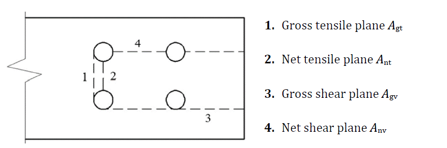
บทนี้มุ่งเน้นการตรวจสอบความถูกต้องของวิธี Component-Based Finite Element (CBFEM) สำหรับการต้านทานการวิบัติแบบ Block Shear ของการเชื่อมต่อโครงสร้างเหล็กแบบสลักเกลียวที่รับแรงเฉือน เทียบกับแบบจำลองไฟไนต์เอลิเมนต์เชิงวิจัย (ROFEM) และแบบจำลองเชิงวิเคราะห์หลัก (AM)
แบบจำลองเชิงวิเคราะห์
มีแบบจำลองเชิงวิเคราะห์หลายแบบสำหรับการต้านทานการวิบัติแบบ Block Shear ของการเชื่อมต่อโครงสร้างเหล็กแบบสลักเกลียว โดยศึกษาแบบจำลองจากมาตรฐาน EN 1993-1-8:2005, EN 1993-1-8:2020, AISC 360-10 และ CSA S16-9 นอกจากนี้ยังใช้แบบจำลองเชิงวิเคราะห์โดย Driver et al. (2005) และ Topkaya et al. (2004) ในการเปรียบเทียบด้วย
โดยที่:
- กำลังคราก
- กำลังสูงสุด
, , - ตัวประกอบความปลอดภัย
สำหรับ , , ดูรูปที่ 5.6.1
การตรวจสอบและยืนยันความถูกต้องของความต้านทาน
การทดสอบโดย Huns et al. (2002) ถูกนำมาใช้สำหรับการตรวจสอบความถูกต้องของ ROFEM ที่สร้างโดย Sekal (2019) ในซอฟต์แวร์ ANSYS ดังแสดงในรูปที่ 5.6.2 โดยใช้ไดอะแกรมวัสดุความเค้น-ความเครียดจริง จำลองเฉพาะแผ่นที่บางที่สุดซึ่งคาดว่าจะวิบัติ สลักเกลียวถูกทำให้ง่ายขึ้นโดยกำหนดเป็นเพียงการเคลื่อนตัวแบบรองรับบนครึ่งวงกลมของรูสลักเกลียว การเคลื่อนตัวในรูทั้งหมดถูกเชื่อมโยงเข้าด้วยกัน แบบจำลอง ROFEM แสดงความสอดคล้องกับผลการทดสอบเป็นอย่างดี
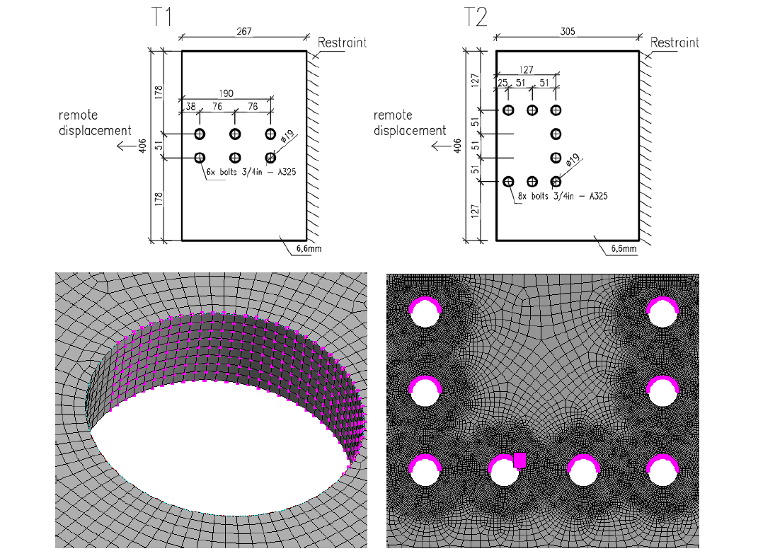
แบบจำลอง CBFEM เชิงการออกแบบใช้ Shell Element ที่มีตาข่ายค่อนข้างหยาบ โดยตาข่ายถูกกำหนดไว้ล่วงหน้าบริเวณรูสลักเกลียว สลักเกลียวถูกจำลองเป็น Spring ไม่เชิงเส้นซึ่งเชื่อมต่อกับ Node ที่ขอบรูสลักเกลียวด้วย Link ใช้ไดอะแกรมวัสดุแบบสองเส้นตรงที่มีการแข็งตัวจากความเครียดน้อยมากสำหรับแผ่นเหล็ก ความต้านทานขีดจำกัดของกลุ่มสลักเกลียวในการรับแรงกดทับถูกกำหนดเมื่อความเครียดพลาสติกในแผ่นเหล็กถึง 5% (EN 1993-1-5: 2005) ความต้านทานการกดทับและการฉีกขาดของรูสลักเกลียวแต่ละตัวถูกตรวจสอบด้วยสูตรในมาตรฐานที่เกี่ยวข้อง
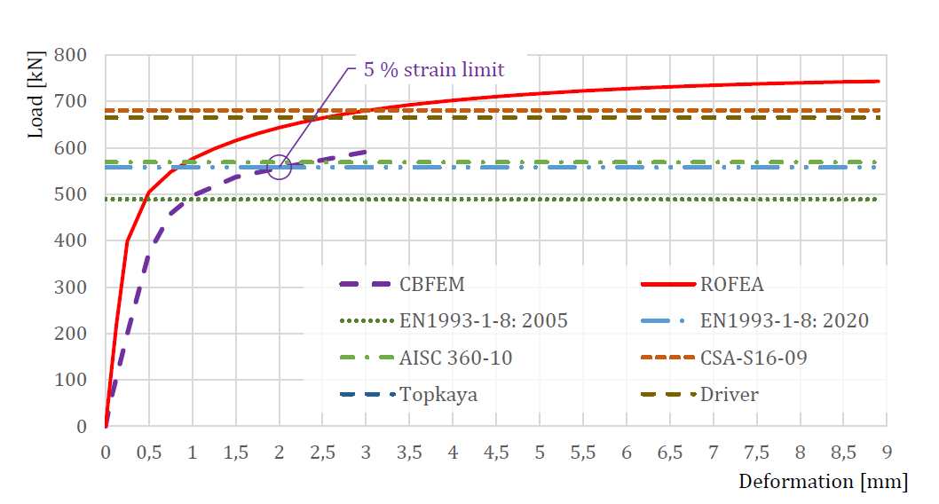
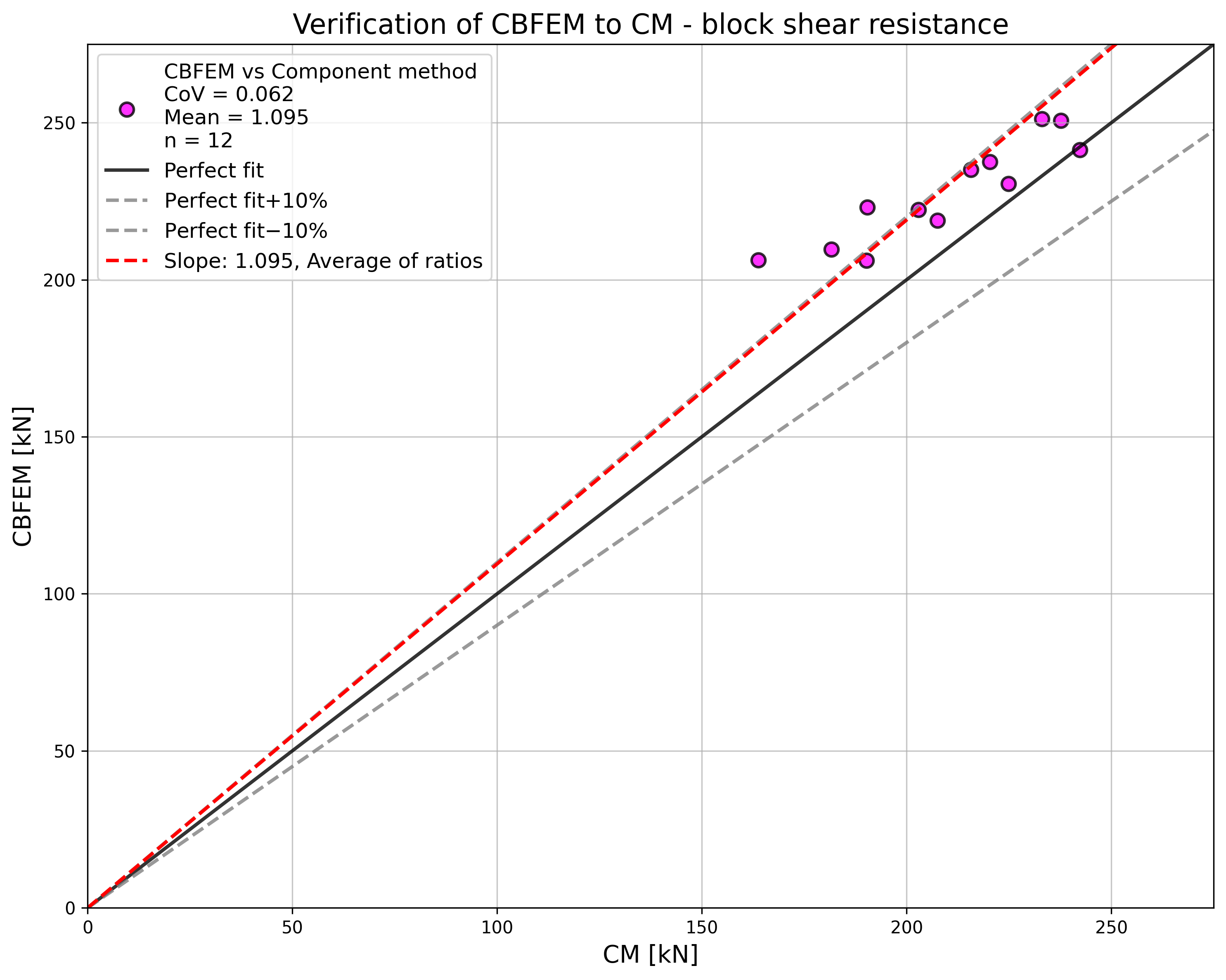
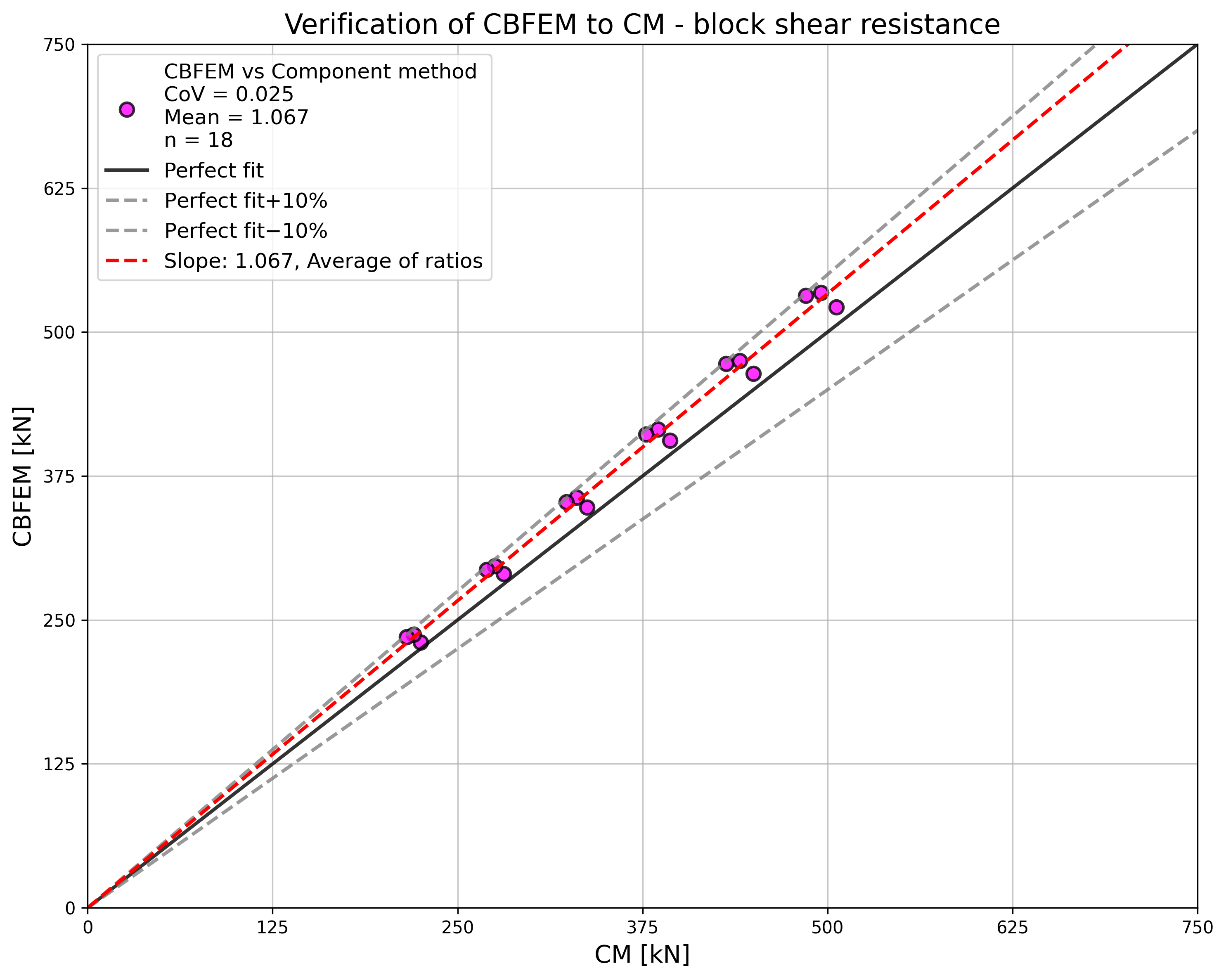
การเปรียบเทียบระหว่าง ROFEM, CBFEM และแบบจำลองเชิงวิเคราะห์แสดงในรูปที่ 5.6.3 แบบจำลองที่อนุรักษ์นิยมที่สุดคือแบบจำลองใน EN 1993-1-8: 2005 เนื่องจากแตกต่างจากแบบจำลองอื่น ตรงที่ใช้ระนาบแรงเฉือนสุทธิร่วมกับกำลังคราก การครากในระนาบแรงเฉือนรวมถูกสังเกตพบในการทดสอบและแบบจำลองเชิงตัวเลข ในมาตรฐานรุ่นถัดไป prEN 1993-1-8:2022 สูตรสำหรับการต้านทานการวิบัติแบบ Block Shear จะถูกเปลี่ยนแปลง ความแข็งของแบบจำลอง CBFEM ต่ำกว่าเมื่อเทียบกับ ROFEM ในการทดสอบ รูถูกเจาะด้วยเส้นผ่านศูนย์กลางเท่ากับสลักเกลียว จึงไม่มีการเลื่อนเริ่มต้น แบบจำลอง ROFEM ก็ไม่คำนึงถึงการเลื่อนเช่นกัน แต่ใน CBFEM แบบจำลองแรงเฉือนของสลักเกลียวถูกประมาณโดยสมมติว่ารูสลักเกลียวมีขนาดมาตรฐาน
การศึกษาความไว
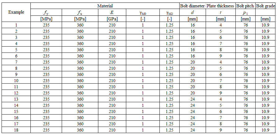
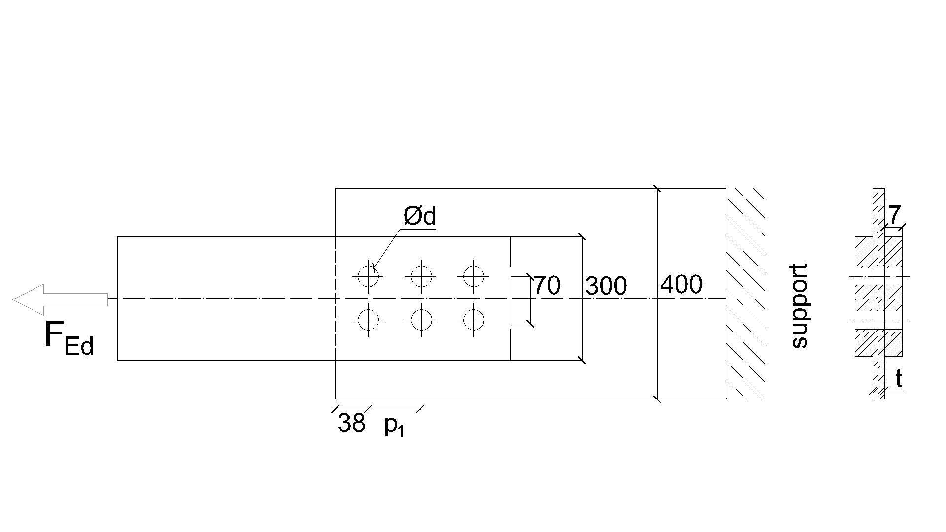
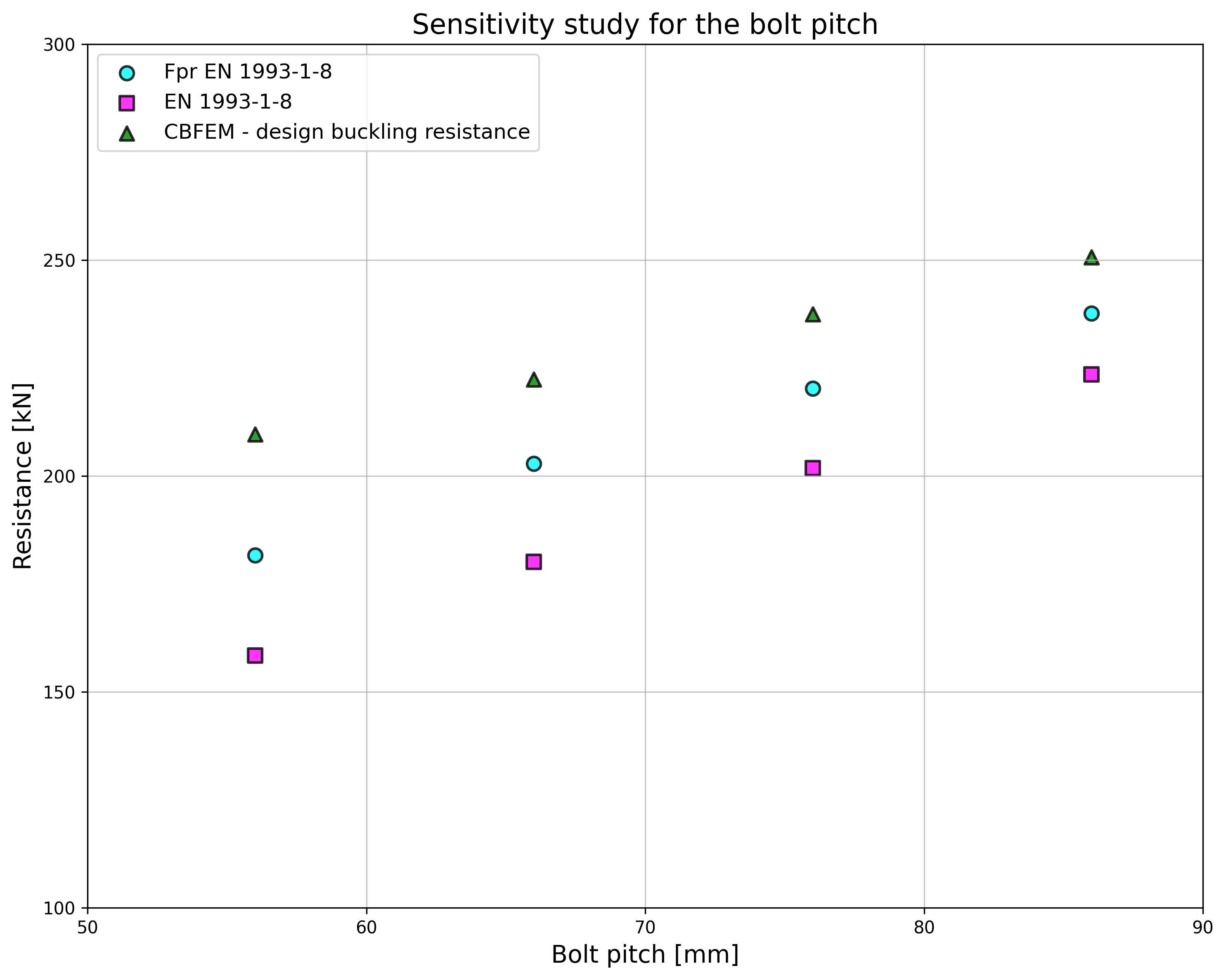
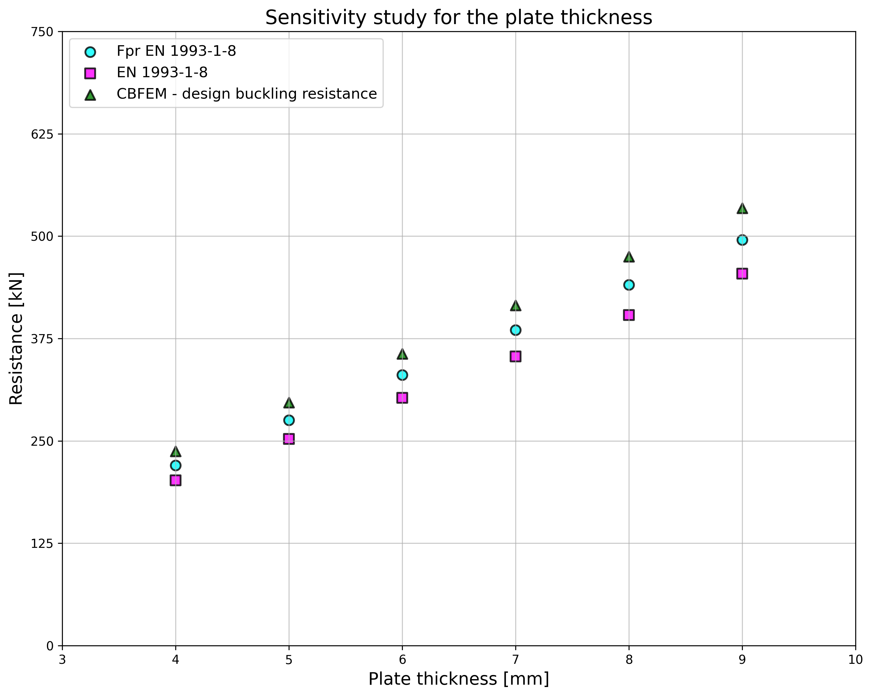
ชิ้นทดสอบ T1 ถูกนำมาใช้ศึกษาว่าระยะห่างระหว่างสลักเกลียว รูปที่ 5.6.4 และความหนาของแผ่นเหล็ก รูปที่ 5.6.6 ส่งผลต่อการต้านทานการวิบัติแบบ Block Shear อย่างไร แบบจำลองให้ผลลัพธ์ตามที่คาดไว้ ตารางที่ 5.6.1 และ 5.6.2 แสดงภาพรวมตัวอย่าง แบบร่าง 5.6.1 แสดงรูปทรงและขนาดของจุดต่อ ผลการตรวจสอบความถูกต้องแสดงในตารางที่ 5.6.3 และ 5.6.4 และในรูปที่ 5.6.5, รูปที่ 5.6.7
ตารางที่ 5.6.1 ภาพรวมตัวอย่าง ผลของระยะห่างระหว่างสลักเกลียว
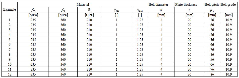
ตารางที่ 5.6.2 ภาพรวมตัวอย่าง ผลของความหนาของแผ่นเหล็ก
ผลของระยะห่างระหว่างสลักเกลียว
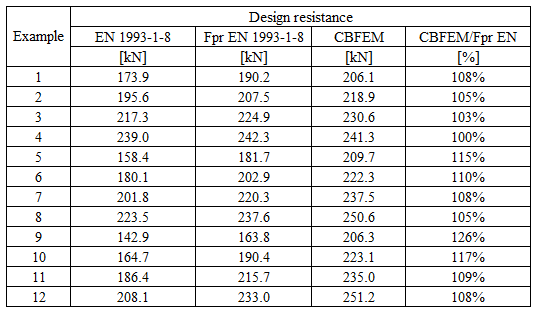
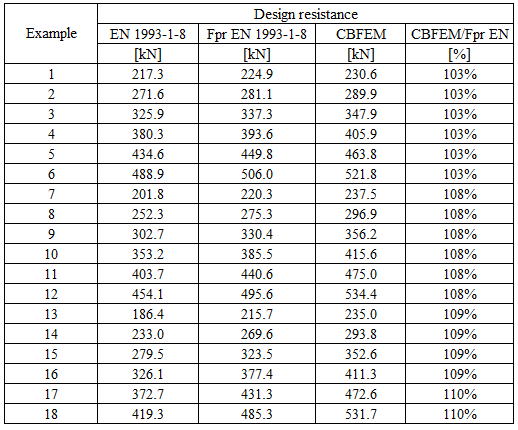
ตารางที่ 5.6.3 การเปรียบเทียบผลของค่าการออกแบบความต้านทานที่ทำนายโดย CBFEM, EN 1993-1-8 และ Fpr EN 1993-1-8 ผลของระยะห่างระหว่างสลักเกลียว
ผลของความหนาของแผ่นเหล็ก
ตารางที่ 5.6.4 การเปรียบเทียบผลของค่าการออกแบบความต้านทานที่ทำนายโดย CBFEM, EN 1993-1-8 และ Fpr EN 1993-1-8 ผลของความหนาของแผ่นเหล็ก
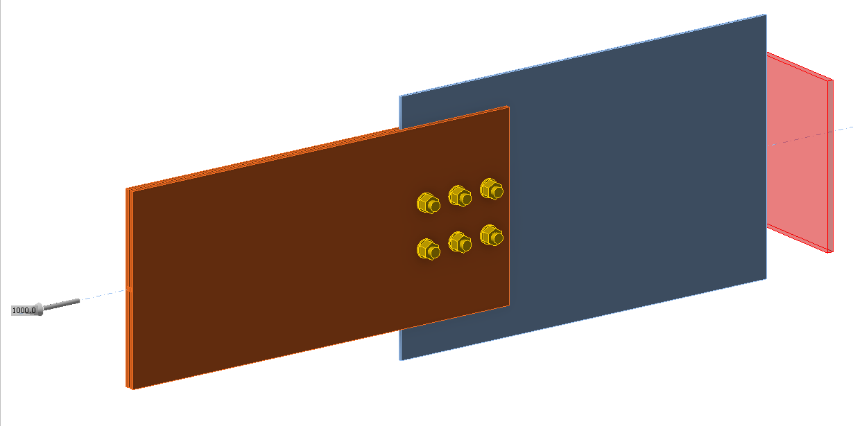
ตัวอย่าง Benchmark
ข้อมูลนำเข้า
ชิ้นส่วน
- เหล็ก S450
- รูปตัด I แบบรีด
- b = 300mm
- h = 19mm
- tf = 7mm
- tw = 6.2mm
แผ่นเหล็ก - ชิ้นส่วนรองรับแรง
- เหล็ก S235
- b = 400mm
- t = 4mm
สลักเกลียว
- 6 × M16 10.9
- ระยะ e1 = 38 mm; p1 = 70 mm; p2 = 56 mm
ผลลัพธ์
- ค่าการออกแบบความต้านทาน NRd = 206.1 kN
- ตัวควบคุมคือความเครียดพลาสติกของแผ่น Gusset
คำอธิบาย
การศึกษานี้มุ่งเน้นไปที่การตรวจสอบวิธี Component-Based Finite Element (CBFEM) สำหรับความต้านทานของการเชื่อมต่อแผ่นปลายด้วยสี่สลักเกลียวในแถว เทียบกับแบบจำลองเชิงวิเคราะห์ (AM) และแบบจำลอง Finite Element เชิงวิจัย (ROFEM) ที่ได้รับการตรวจสอบความถูกต้องจากการทดลอง
แบบจำลองเชิงวิเคราะห์
ความต้านทานของสลักเกลียวต่อแรงเฉือนและแรงดึง และความต้านทานของแผ่นเหล็กต่อแรงกดทับและแรงเฉือนเจาะ ได้รับการออกแบบตาม Tab. 3.4, Chapter 3.6.1 ใน EN 1993-1-8:2006 T-stub สมมูลในแรงดึง ตาม Chapter 6.2.4 ได้รับการปรับปรุงโดย Jaspart et al. (2010) ดู Fig. 5.7.1 และ Tab. 5.7.1
Tab. 5.7.1 รูปแบบการวิบัติของ T-stub ที่มีสี่สลักเกลียวในแถว (Jaspart et al. 2010)
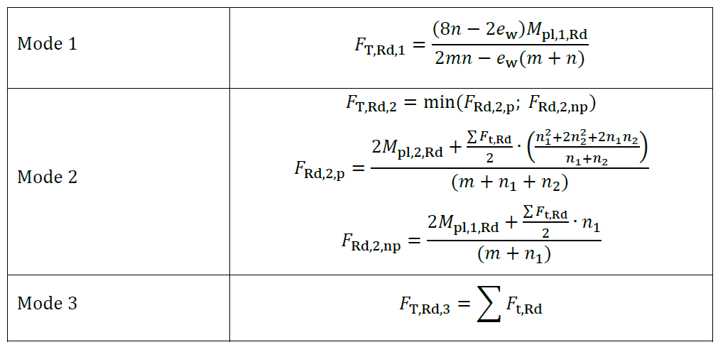
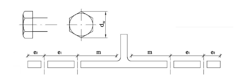
ใน Tab 5.7.1 นั้น 𝐹t,Rd คือความต้านทานแรงดึงของสลักเกลียว, 𝑒w=𝑑w/4, 𝑑w คือเส้นผ่านศูนย์กลางของแหวนรอง หรือความกว้างระหว่างจุดของหัวสลักเกลียวหรือน็อต ตามความเหมาะสม, 𝑚, 𝑛=𝑒1+𝑒2;𝑛≤1.25𝑚, 𝑛1=𝑒1, 𝑛2=𝑒2;𝑛2≤1,25𝑚+𝑛1 ดู Fig. 5.8.2, 𝑀pl,1,Rd=0.25𝑙eff,1𝑡f2𝑓y/𝛾M0, 𝑀pl,2,Rd=0.25𝑙eff,2𝑡f2𝑓y/𝛾M0, 𝑙eff คือความยาวประสิทธิผล, 𝑡f คือความหนาของปีก และ 𝑓y คือกำลังครากของเหล็ก ดู Fig. 5.7.2
การตรวจสอบความถูกต้องและการยืนยันความต้านทาน
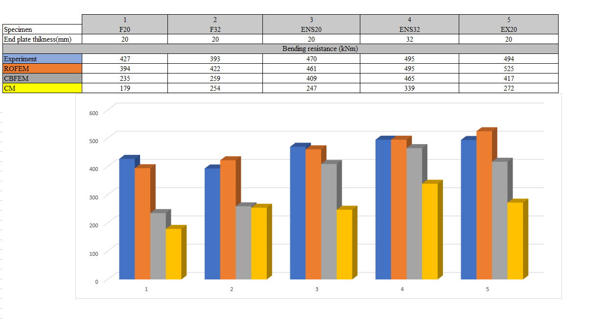
ค่าการออกแบบความต้านทานที่คำนวณโดย CBFEM ได้รับการเปรียบเทียบกับผลลัพธ์ของแบบจำลองเชิงวิเคราะห์ (Zakouřil, 2019) และการทดลองร่วมกับแบบจำลอง Finite Element เชิงวิจัย (Samaan et al. 2017) ดู Fig. 5.7.3 ผลลัพธ์สรุปไว้ใน Fig. 5.7.4 ใช้สลักเกลียวเกรด 8.8 และเหล็กเกรด S450 กำลังครากและกำลังดึงสูงสุดสอดคล้องกับค่าทดลองอย่างใกล้ชิด เช่น กำลังครากของสลักเกลียวคือ 600 MPa และกำลังดึงสูงสุดของสลักเกลียวคือ 800 MPa
ความต้านทานโมเมนต์ดัดที่กำหนดโดย CBFEM มักอยู่ระหว่างความต้านทานที่กำหนดโดยวิธีส่วนประกอบและจากการทดลอง ตาราง 5.7.2 แสดงการเปรียบเทียบระหว่างความต้านทานของ CM, CBFEM, ROFEM และการทดลองสำหรับชิ้นทดสอบที่มีความหนาแผ่นปลาย 20 มม. และ 32 มม. ทั้งวิธีส่วนประกอบและ CBFEM ต่างประเมินความต้านทานของชิ้นทดสอบที่มีแผ่นปลายแบบ Flushed ต่ำกว่าความเป็นจริง
Tab. 5.7.2 การเปรียบเทียบระหว่าง CM, ROFEM, CBFEM และการทดลอง
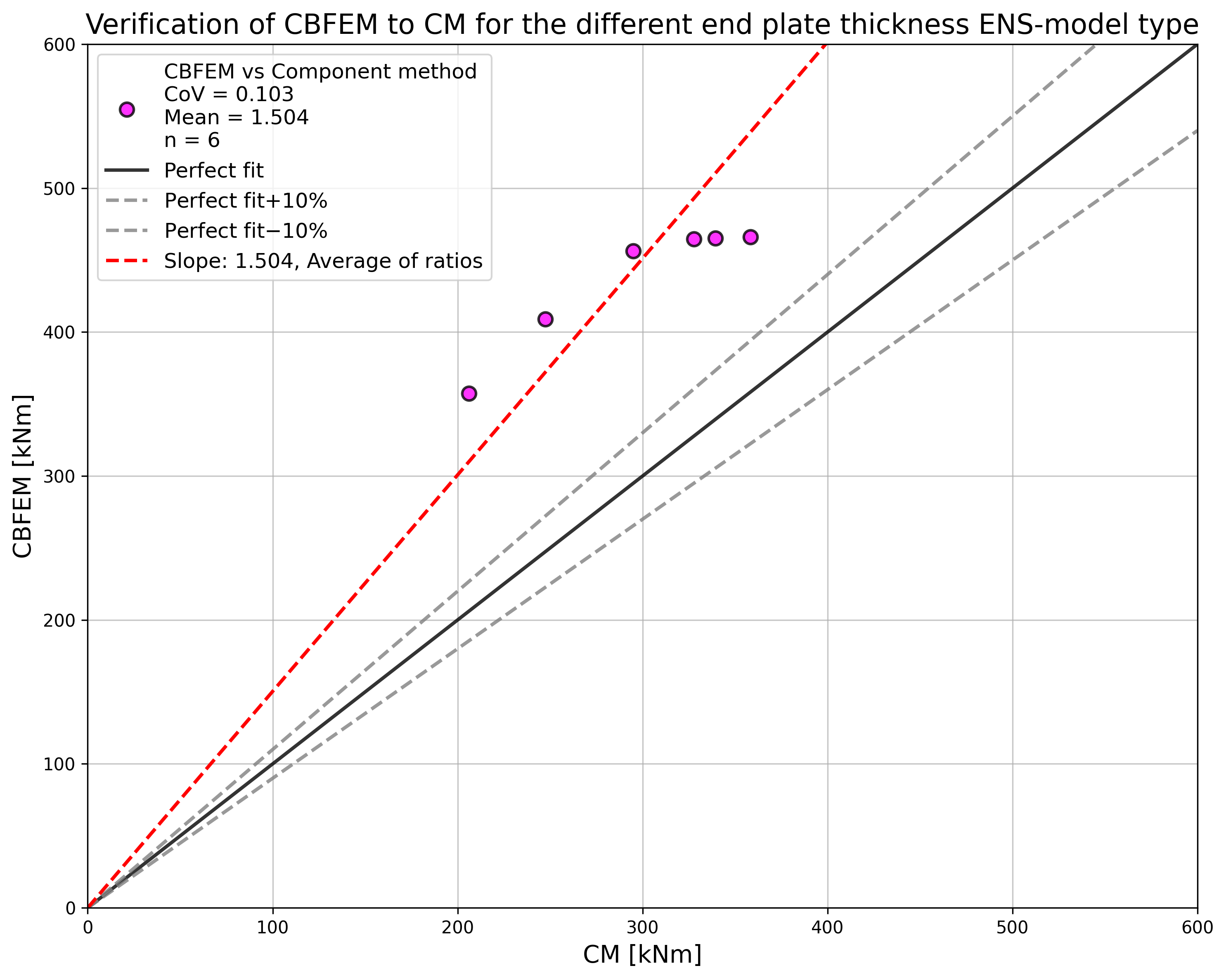
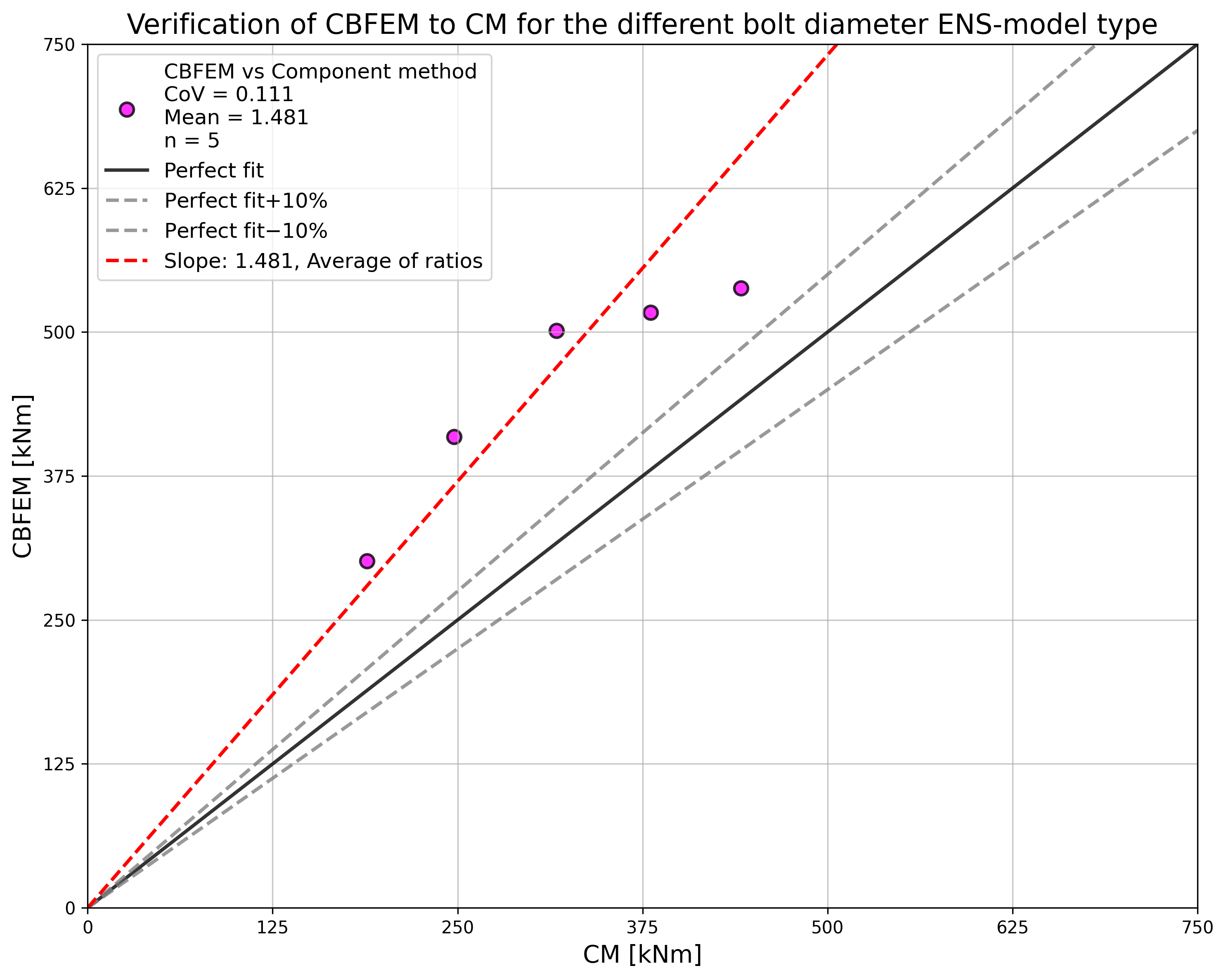
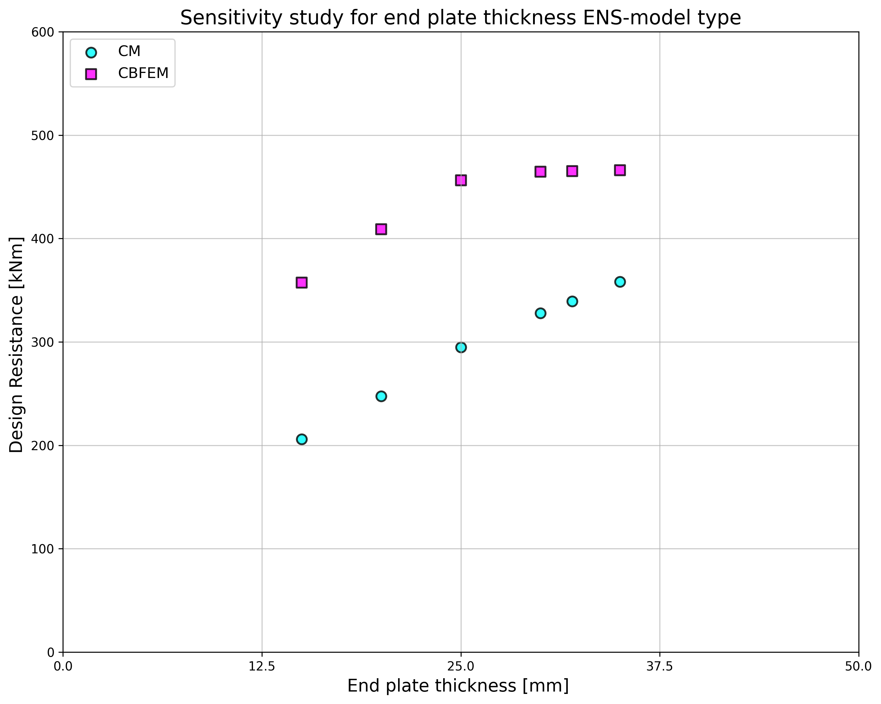
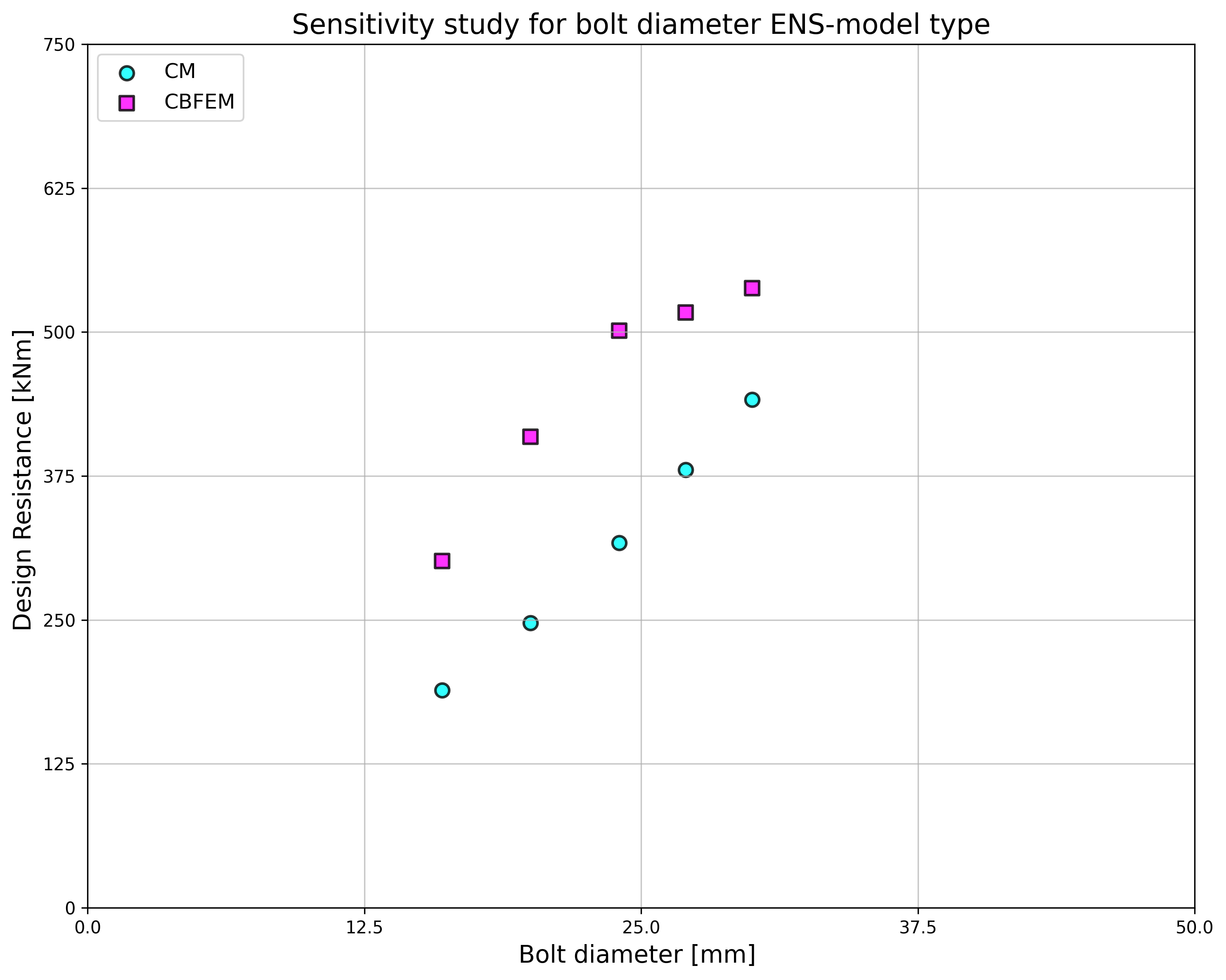
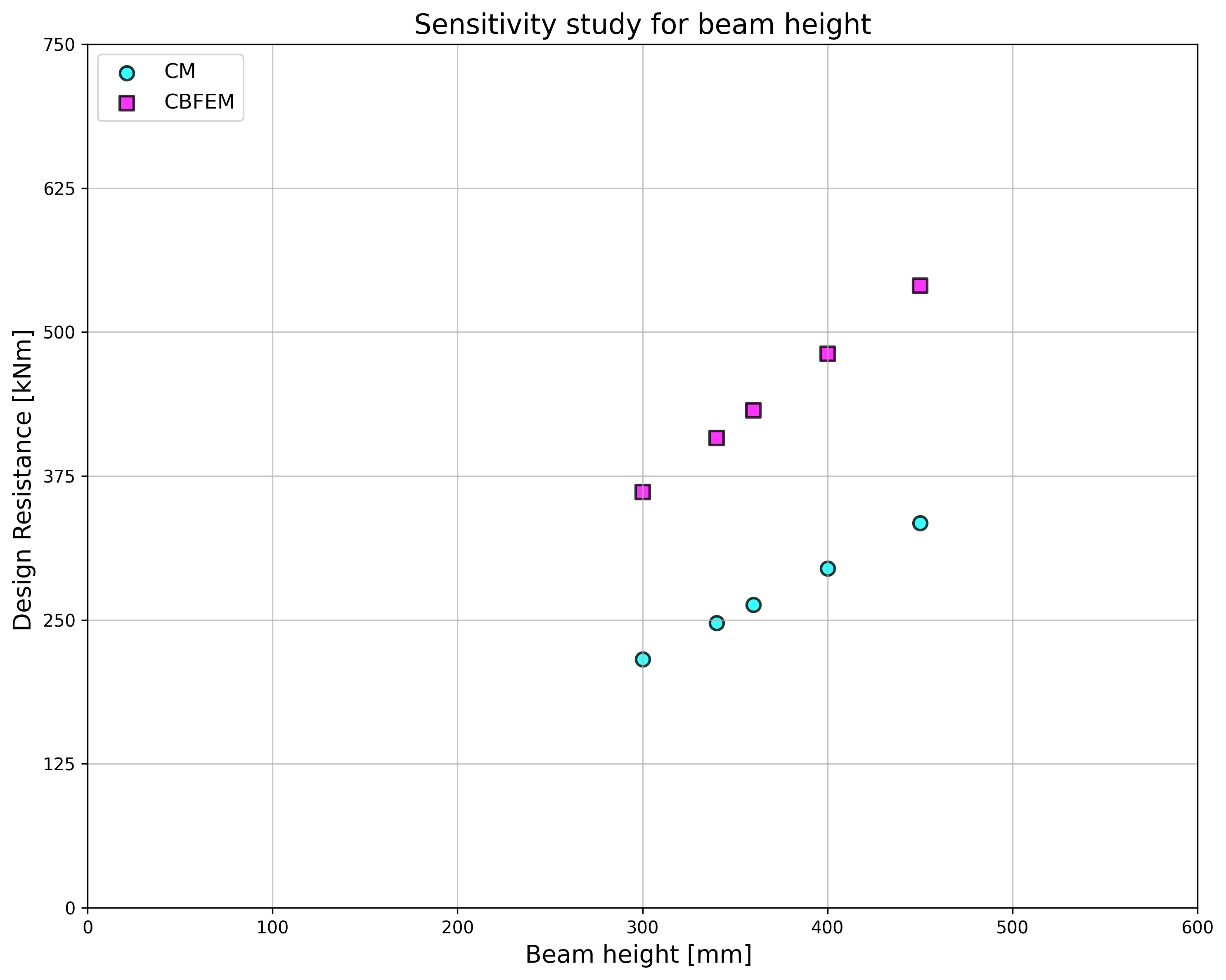
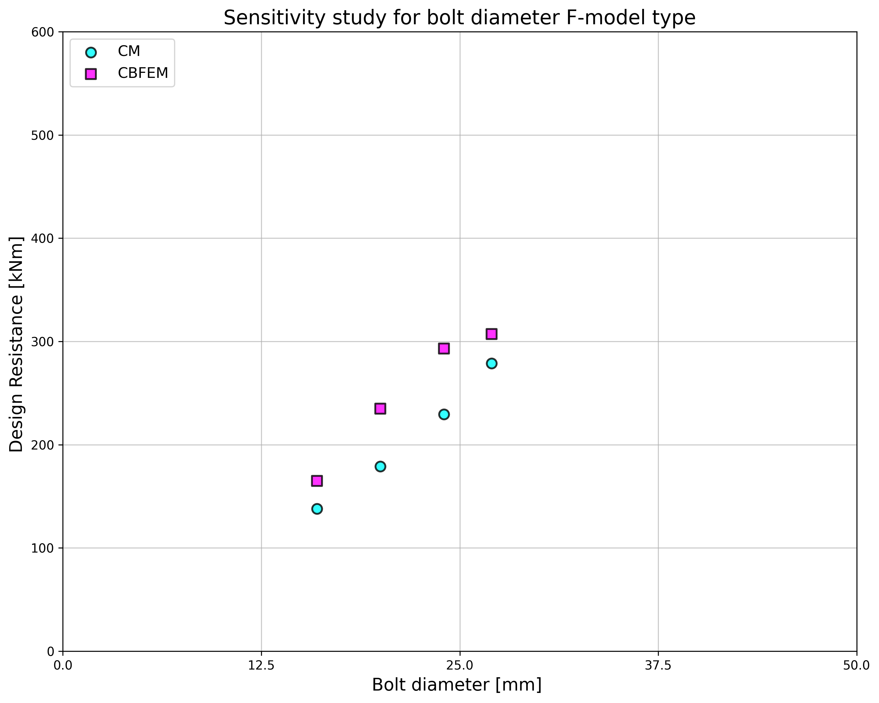
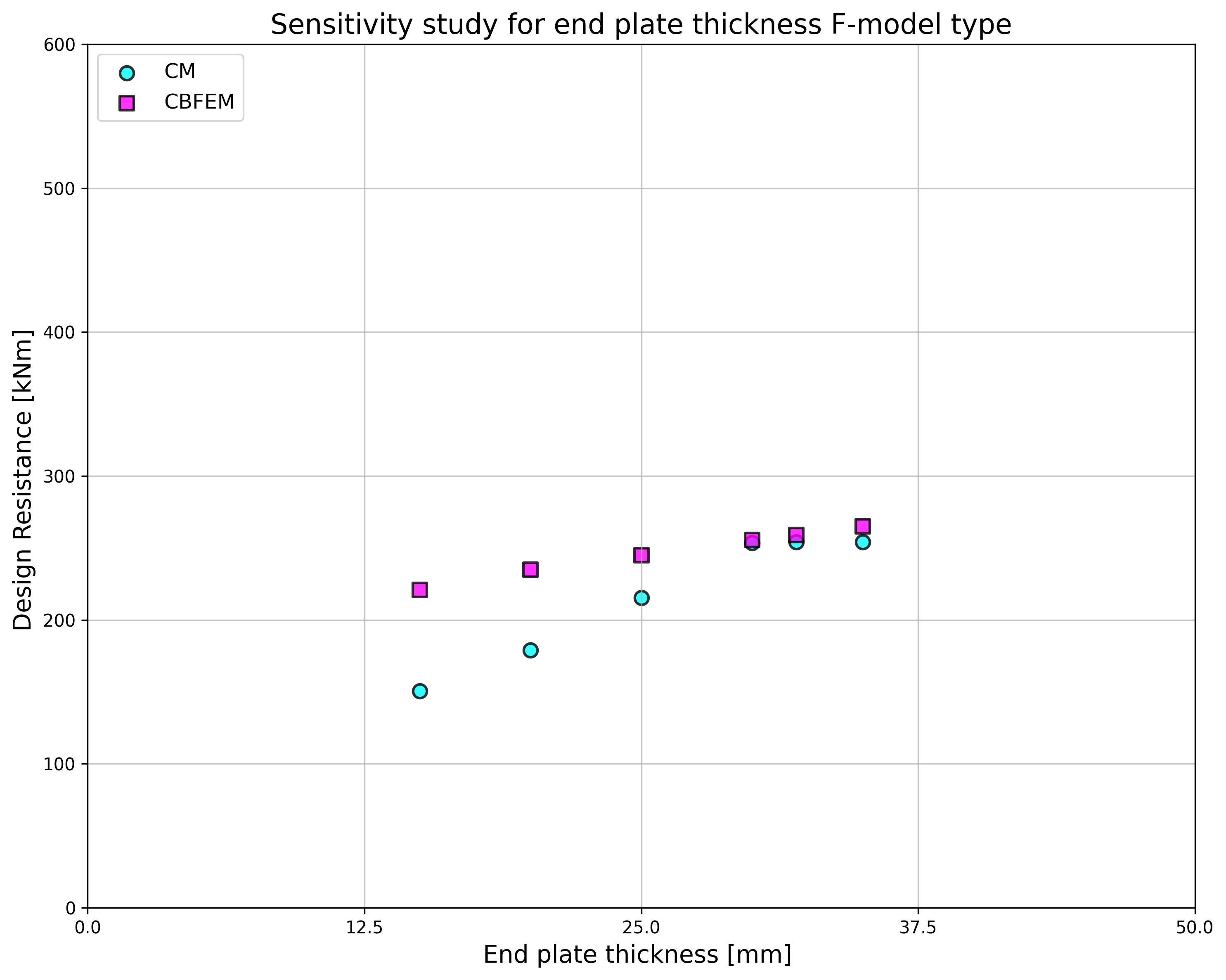
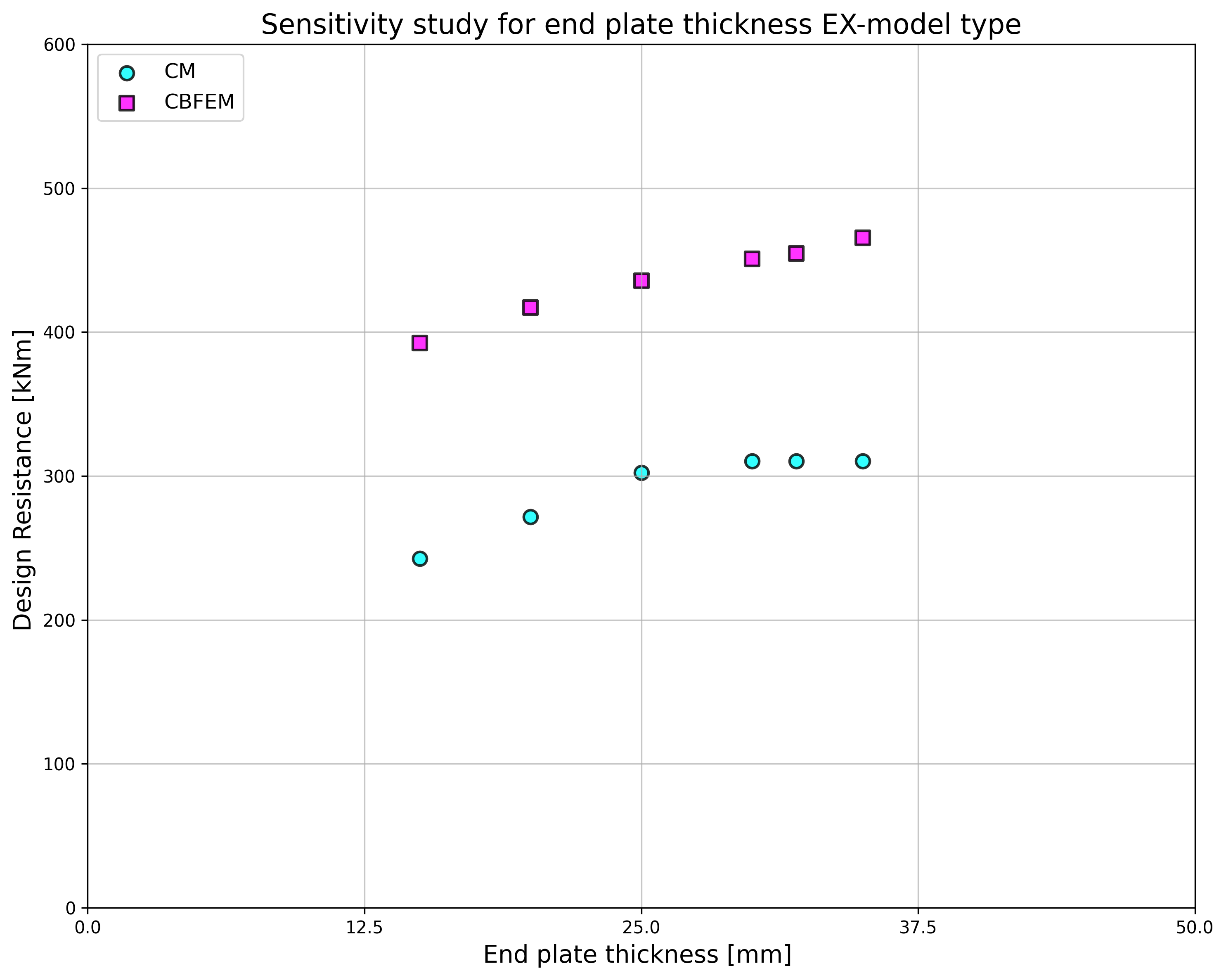
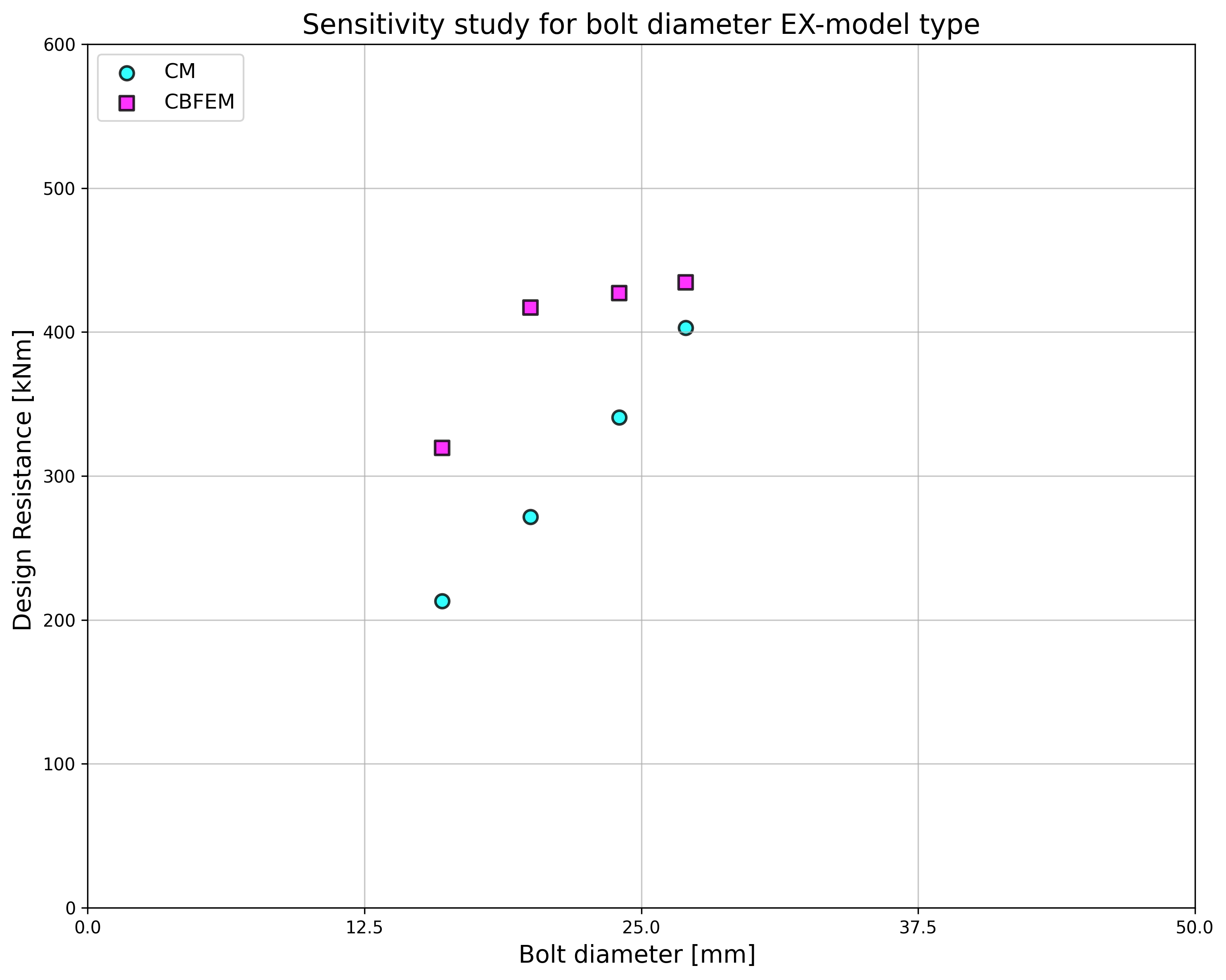
ตาราง 5.7.3 และ Fig. 5.7.4 แสดงการยืนยัน CBFEM เทียบกับ CM สำหรับแบบจำลอง ENS ที่มีความหนาแผ่นปลาย เส้นผ่านศูนย์กลางสลักเกลียว และความสูงคานที่แตกต่างกัน
Tab. 5.7.3 การยืนยัน CBFEM เทียบกับ CM ENS
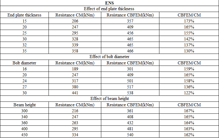
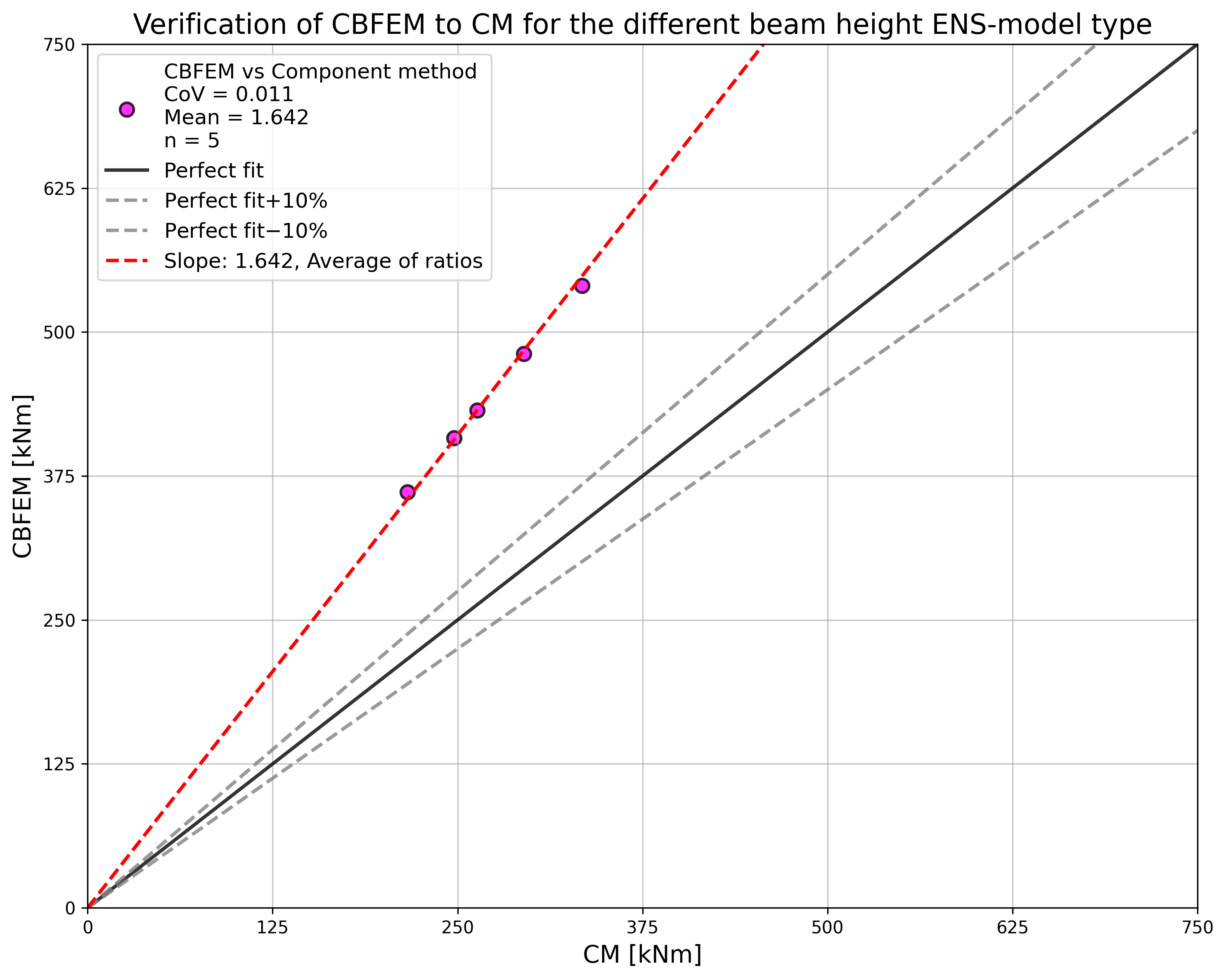
ผลลัพธ์ของการศึกษาความไว (Sensitivity study) สรุปไว้ในกราฟใน Fig. 5.7.5, Fig. 5.7.6, Fig. 5.7.7
ตาราง 5.7.4 และ Fig. 5.7.8 แสดงการยืนยัน CBFEM เทียบกับ CM สำหรับแบบจำลอง F ที่มีความหนาแผ่นปลายและเส้นผ่านศูนย์กลางสลักเกลียวที่แตกต่างกัน
Tab. 5.7.4 การยืนยัน CBFEM เทียบกับ CM F
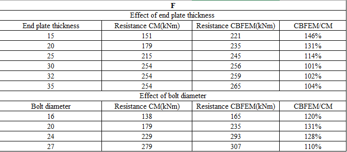

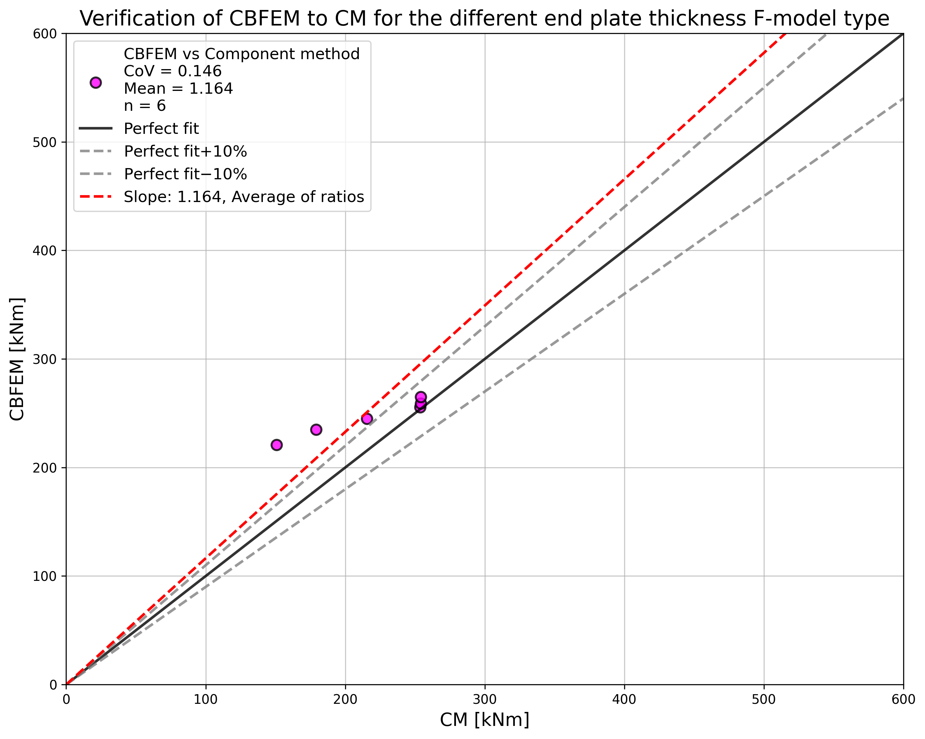
ผลลัพธ์ของการศึกษาความไวสรุปไว้ในกราฟใน Fig. 5.7.9 และ 5.7.10
ตาราง 5.7.5 และ Fig. 5.7.11 แสดงการยืนยัน CBFEM เทียบกับ CM สำหรับแบบจำลอง F ที่มีความหนาแผ่นปลายและเส้นผ่านศูนย์กลางสลักเกลียวที่แตกต่างกัน
Tab. 5.7.5 การยืนยัน CBFEM เทียบกับ CM EX
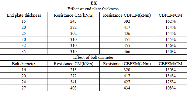
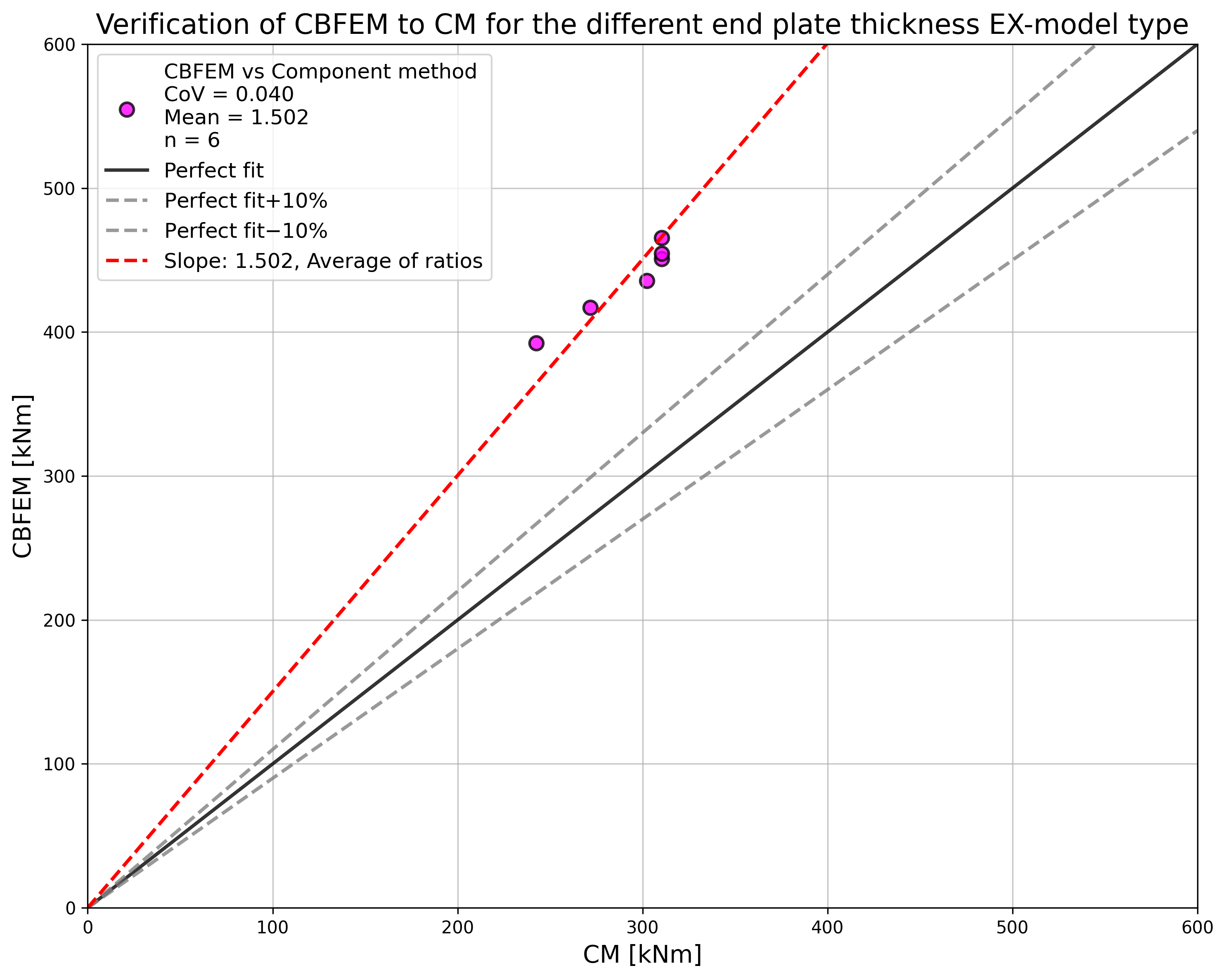
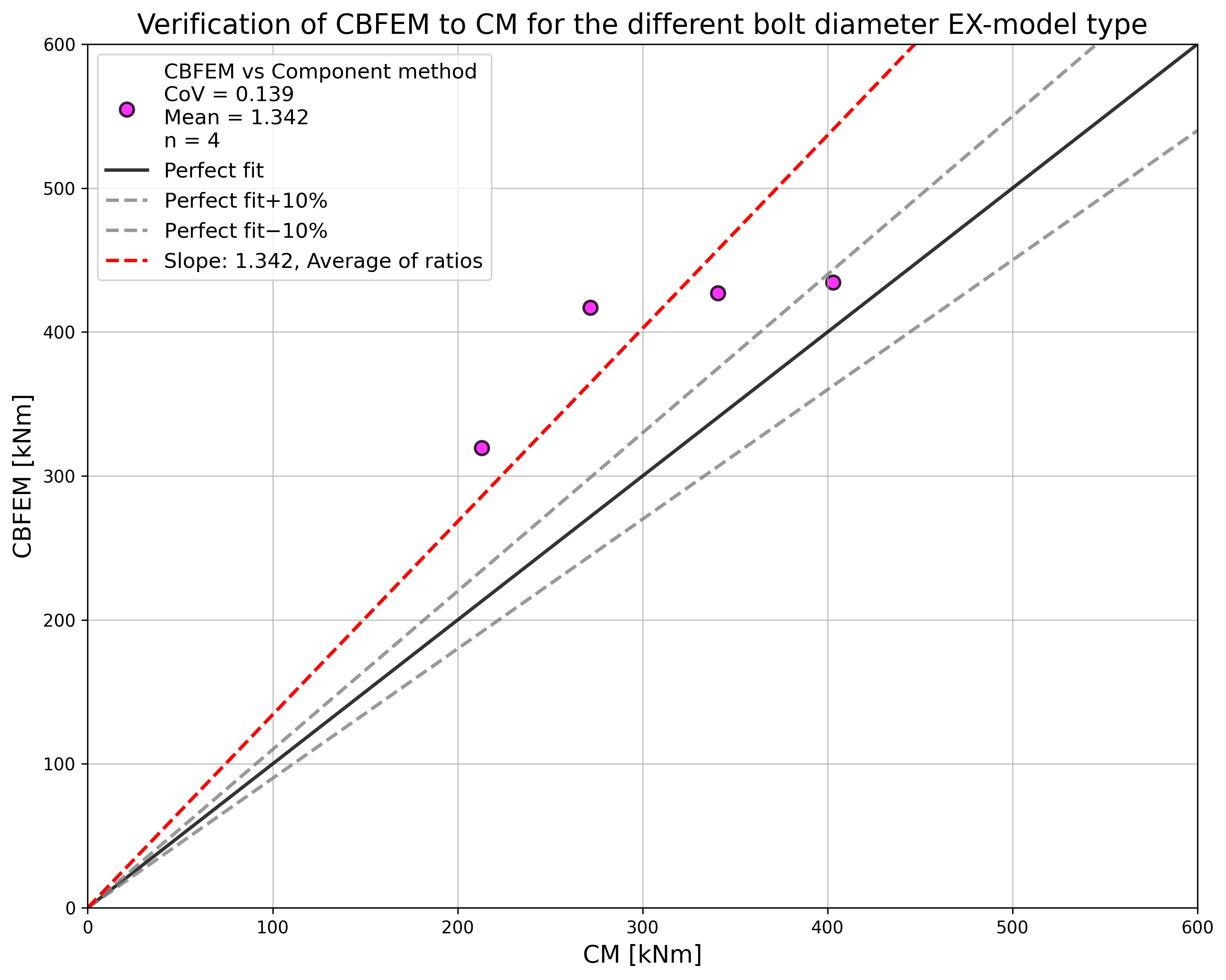
ผลลัพธ์ของการศึกษาความไวสรุปไว้ในกราฟใน Fig. 5.7.12 และ 5.7.13
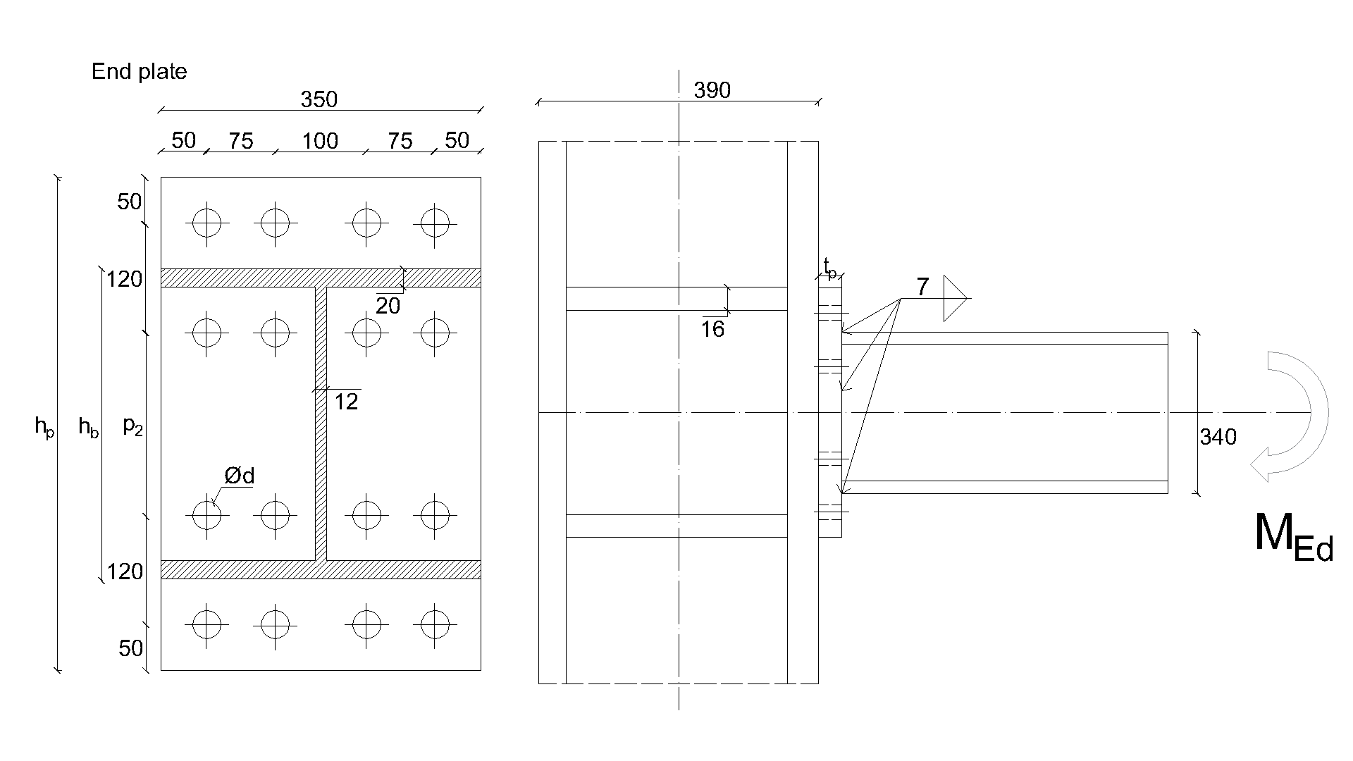
ตัวอย่าง Benchmark
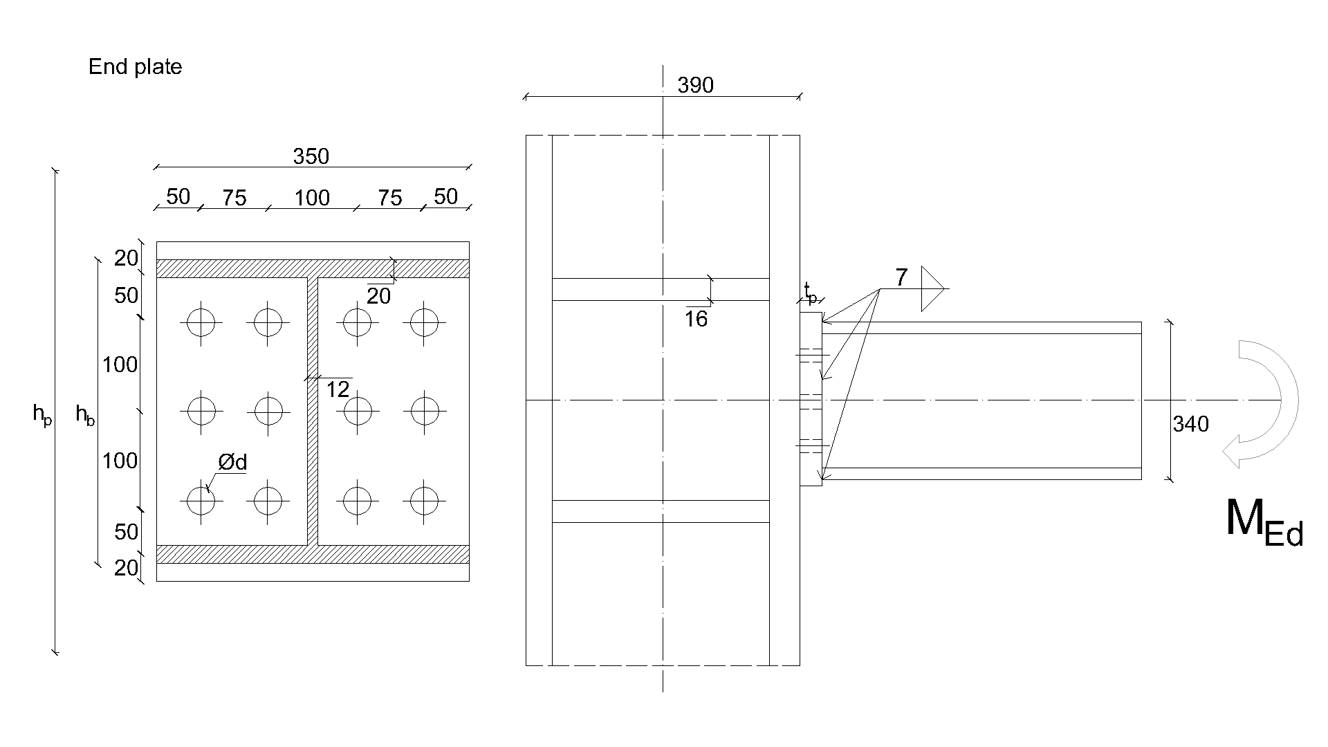
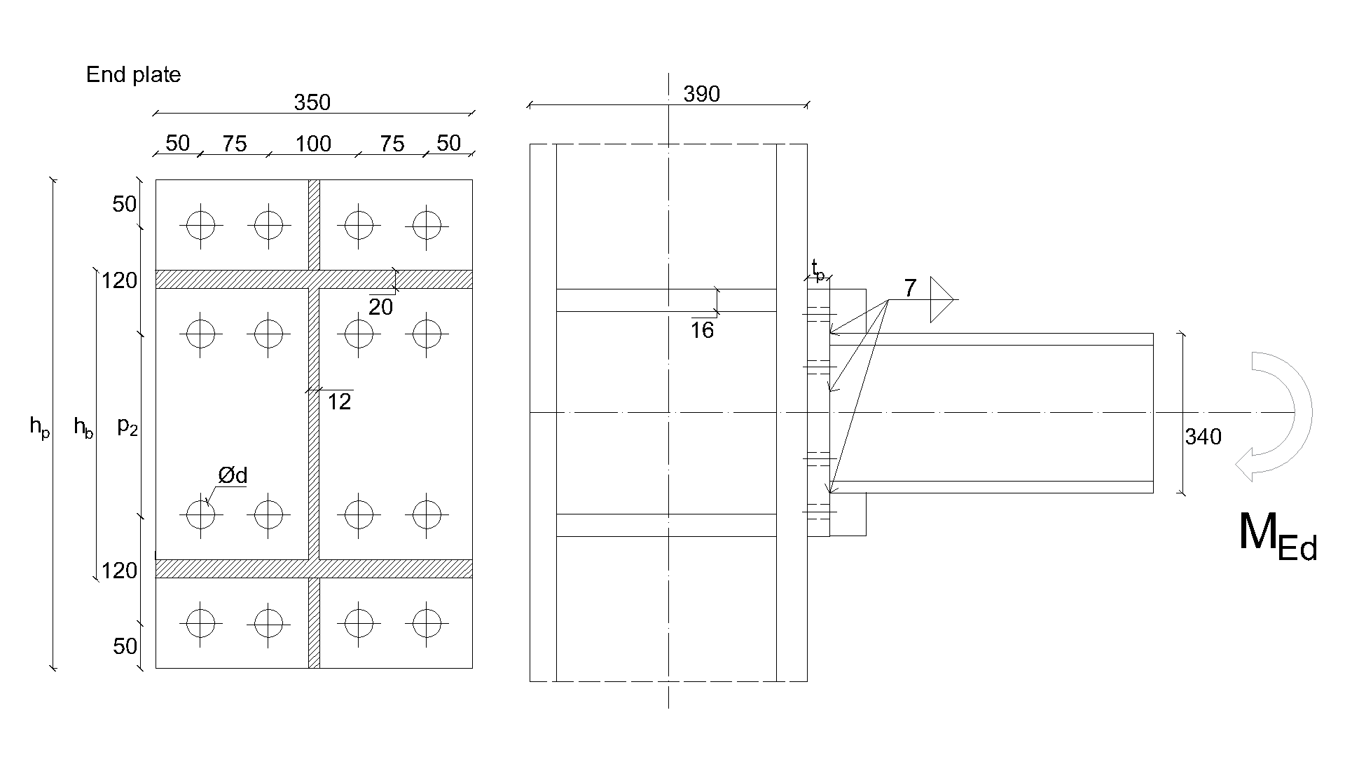
ข้อมูลนำเข้า
- เหล็ก S450
เสา
- รูปตัด I แบบรีด
- h = 390mm
- b = 350mm
- tf = 20mm
- tw = 12mm
- r = 27mm
แผ่นเสริมความแข็งเสา
- ts = 16mm
คาน
- รูปตัด I แบบรีด
- hb = 340mm
- bb = 350mm
- tf = 20mm
- tw = 12mm
- r = 27mm
แผ่นปลาย
- tp = 20mm
- bp = 350mm
- hp= 540mm
สลักเกลียว
- 4 แถว x 4 x M16 8.8
- ระยะห่าง e1 = 50 mm, p1 = 120 mm, p2 = 100mm, e2= 50mm, w1 = 75mm, w2 = 100mm
รอยเชื่อม
- aw = 7mm
ผลลัพธ์
- ค่าการออกแบบความต้านทาน FRd = 247 kN
- ส่วนประกอบวิกฤตคือสลักเกลียวที่มีแรงเพิ่มขึ้นจากแรงงัดของแผ่นปลาย
แผ่นบางรับแรงอัด
คำอธิบาย
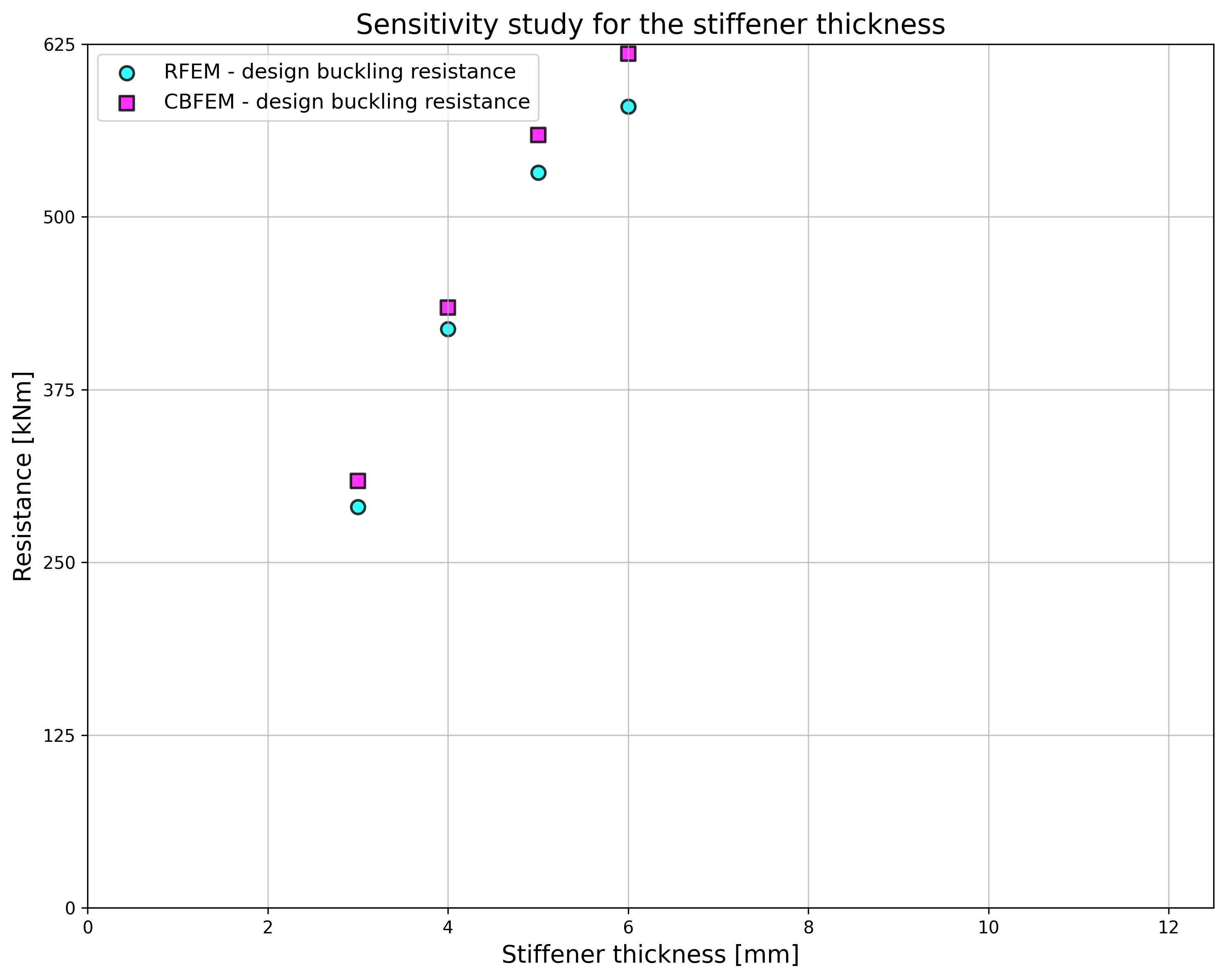
วัตถุประสงค์ของการศึกษานี้คือการตรวจสอบวิธี Component-Based Finite Element (CBFEM) สำหรับส่วนเสริมคานรูปสามเหลี่ยมชั้น 4 ที่ไม่มีปีก และส่วนเสริมคานรูปสามเหลี่ยมชั้น 4 ที่มีปีกพร้อมความแข็งเกร็งที่ลดลง โดยเปรียบเทียบกับแบบจำลอง FEM เพื่อการวิจัย (RFEM) และแบบจำลอง FEM เพื่อการออกแบบ (DFEM)
การทดสอบเชิงทดลอง
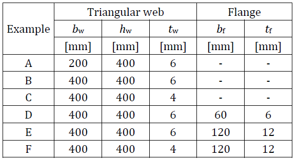
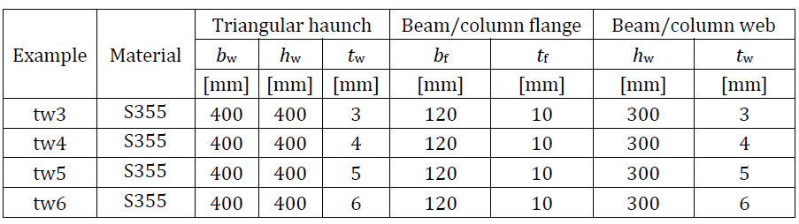
นำเสนอผลการทดลองของชิ้นทดสอบส่วนเสริมคานจำนวนหกชิ้น ทั้งแบบมีและไม่มีปีก โดยสามชิ้นไม่มีปีก และอีกสามชิ้นได้รับการรองรับด้วยปีกเพิ่มเติม ชิ้นทดสอบที่ไม่มีแผ่นเสริมความแข็งแตกต่างกันที่ความหนาของเอว tw และความกว้างของเอว bw ชิ้นทดสอบที่มีการเสริมแรงแตกต่างกันที่ความหนาของเอว tw ความหนาของปีก tf และความกว้างของปีก bf ขนาดของชิ้นทดสอบสรุปไว้ใน Tab. 6.1.1 การตั้งค่าการทดสอบสำหรับชิ้นทดสอบที่ไม่มีปีกแสดงใน Fig. 6.1.1 (บน) และสำหรับชิ้นทดสอบที่มีปีกแสดงใน Fig. 6.1.1 (ล่าง) คุณสมบัติของวัสดุแผ่นเหล็กสรุปไว้ใน Tab. 6.1.2
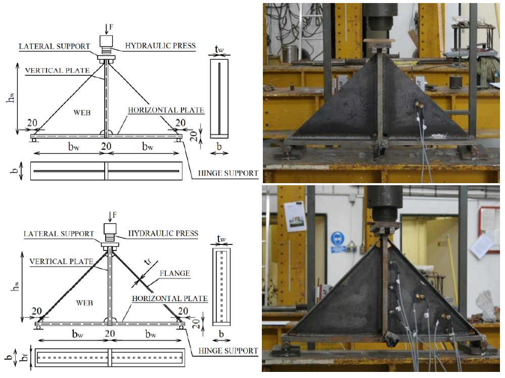
Tab. 6.1.1 ภาพรวมตัวอย่าง
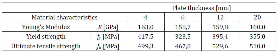
Tab. 6.1.2 คุณสมบัติของวัสดุที่ใช้ในแบบจำลองเชิงตัวเลข
แบบจำลอง FEM เพื่อการวิจัย
แบบจำลอง FEM เพื่อการวิจัย (RFEM) ใช้สำหรับตรวจสอบแบบจำลอง DFEM และได้รับการยืนยันความถูกต้องจากการทดลอง ในแบบจำลองเชิงตัวเลข ใช้องค์ประกอบเปลือกสี่เหลี่ยมสี่โหนดที่มีโหนดอยู่ที่มุม โดยมีความยาวด้านสูงสุด 10 มม. ใช้การวิเคราะห์แบบไม่เชิงเส้นทั้งทางวัสดุและทางเรขาคณิตพร้อมความไม่สมบูรณ์ (GMNIA) ความไม่สมบูรณ์ทางเรขาคณิตสมมูลได้มาจากรูปแบบการโก่งเดาะแรกสุด และกำหนดแอมพลิจูดตาม Annex C ของ EN 1993-1-5:2006 แบบจำลองเชิงตัวเลขแสดงใน Fig. 6.1.2
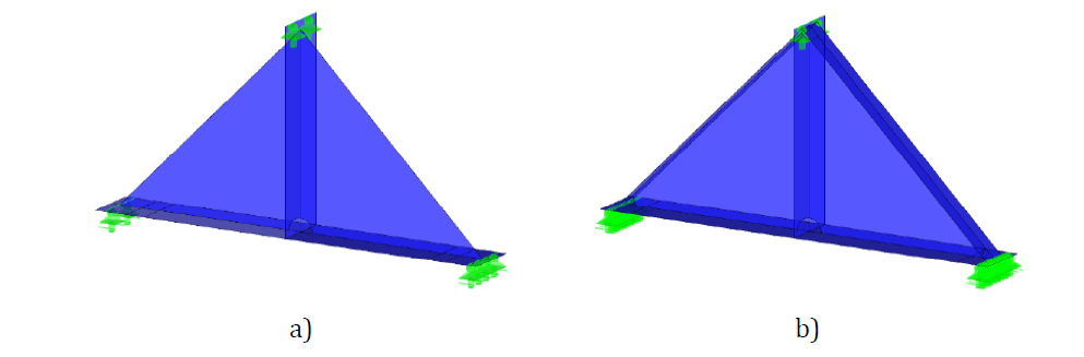
\textsf{\textit{\footnotesize{Fig. 6.1.2 Research FEM model a) haunch without a flange b) haunch with a flange}}
ตัวอย่างการเปรียบเทียบ RFEM กับการทดสอบเชิงทดลองในด้านพฤติกรรมแรง-การโก่งตัวแสดงใน Fig. 6.1.3a การเปรียบเทียบความต้านทานที่วัดได้จากการทดลองและที่ได้จาก RFEM แสดงใน Fig. 6.1.3b ความต้านทานที่คำนวณจากแบบจำลองเชิงตัวเลขแสดงบนแกนนอน ความต้านทานที่วัดได้จากการศึกษาเชิงทดลองแสดงบนแกนตั้ง จะเห็นได้ว่ามีความสอดคล้องกันเป็นอย่างดี
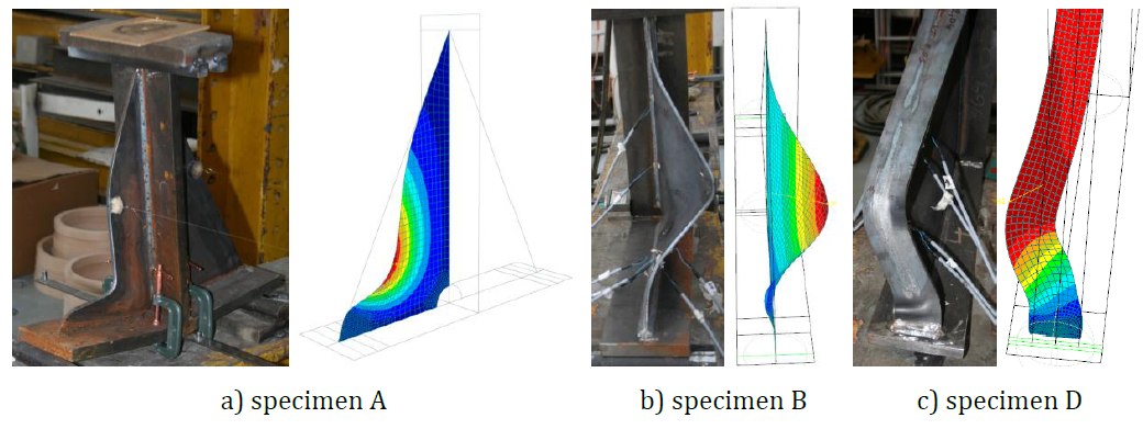
การเปรียบเทียบสภาวะการเสียรูปขั้นสุดท้ายระหว่างการจำลองเชิงตัวเลขและผลการทดลองดำเนินการเมื่อสิ้นสุดการทดสอบ Fig. 6.1.4 แสดงการเปรียบเทียบการเสียรูปของชิ้นทดสอบ A, B และ D หลังการวิบัติกับ RFEA พบว่ามีความสอดคล้องกันเป็นอย่างดีระหว่างแบบจำลองเชิงตัวเลขและผลการทดลองของส่วนเสริมคานในรูปแบบการวิบัติ สำหรับรายละเอียดเพิ่มเติม ดู (Kurejková and Wald, 2017)
แบบจำลอง FEM เพื่อการออกแบบ
ขั้นตอนการออกแบบสำหรับหน้าตัดชั้น 4 อธิบายไว้ในหัวข้อ 3.10 การโก่งเดาะเฉพาะที่
ขั้นตอนการออกแบบได้รับการตรวจสอบโดยการเปรียบเทียบแบบจำลอง DFEM และ RFEM ทั้งสองแบบจำลองสร้างขึ้นในซอฟต์แวร์ Dlubal RFEM ขั้นตอนนี้ถูกนำไปใช้ในแบบจำลอง CBFEM ดู (Kurejková et al. 2015) ความต้านทานที่ควบคุมด้วยความเครียดพลาสติก 5% ได้มาในขั้นตอนแรก ตามด้วยการวิเคราะห์การโก่งเดาะเชิงเส้น ชิ้นส่วนวิกฤตในการวิเคราะห์การโก่งเดาะได้รับการศึกษา ความต้านทานการออกแบบถูกประมาณค่าจนกว่าเงื่อนไข ρ∙αult,k = 1 จะสำเร็จ
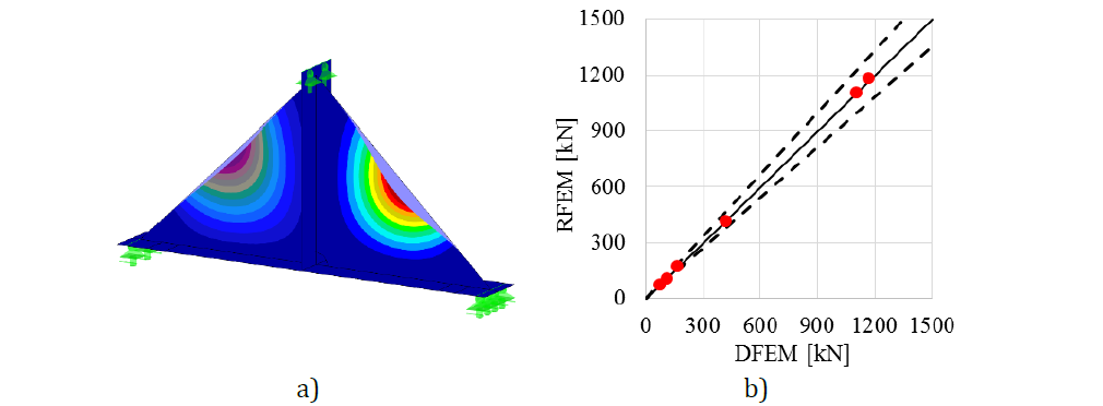
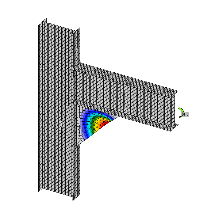
รูปแบบการโก่งเดาะแรกสุดของส่วนเสริมคานที่ไม่มีปีกแสดงใน Fig. 6.1.5 a) ความต้านทานประเมินตามสูตร (3.10.2) ในหัวข้อ 3.10 การเปรียบเทียบความต้านทานของ DFEM และ RFEM แสดงใน Fig. 6.1.5 b) ความต้านทานที่คำนวณใน DFEM แสดงบนแกนนอน ความต้านทานที่คำนวณใน RFEM แสดงบนแกนตั้ง จะเห็นได้ว่ามีความสอดคล้องกันเป็นอย่างดีและขั้นตอนได้รับการตรวจสอบแล้ว
พฤติกรรมโดยรวมและการตรวจสอบ
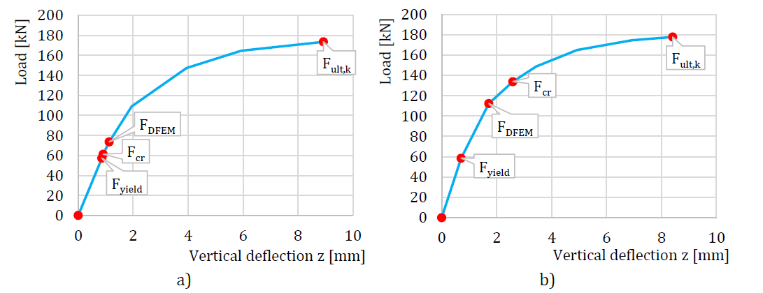
จัดทำการเปรียบเทียบพฤติกรรมโดยรวมของส่วนเสริมคานที่ไม่มีปีกโดยใช้แผนภาพแรง-การโก่งตัวในแบบจำลอง DFEM การโก่งตัววัดในทิศทางแนวตั้งที่กึ่งกลางของชิ้นทดสอบ ให้ความสนใจกับลักษณะสำคัญ ได้แก่ ความต้านทานการออกแบบและแรงวิกฤต เลือกตัวอย่างส่วนเสริมคานที่ไม่มีปีกสองตัวอย่างเพื่อนำเสนอเป็นข้อมูลอ้างอิง ดู Fig. 6.1.6 ขั้นตอนการออกแบบในแบบจำลอง DFEM ครอบคลุมสำรองหลังการโก่งเดาะ ซึ่งสังเกตได้ใน Fig. 6.1.6 a) แรงวิกฤต Fcr มีค่าน้อยกว่าความต้านทานการออกแบบ FDFEM สำรองหลังการโก่งเดาะสังเกตได้ในกรณีที่มีแผ่นบางมาก แผนภาพทั่วไปแสดงใน Fig. 6.1.6 b) ซึ่งความต้านทานการออกแบบ FDFEM ไม่ถึงแรงวิกฤต Fcr แรง Fult,k หมายถึงความต้านทานที่ความเครียดพลาสติก 5%
ขั้นตอนการออกแบบในแบบจำลอง CBFEM อธิบายไว้ในหัวข้อ 3.10 การโก่งเดาะเฉพาะที่ การวิเคราะห์การโก่งเดาะถูกนำไปใช้ในซอฟต์แวร์ การคำนวณความต้านทานการออกแบบดำเนินการด้วยตนเองตามขั้นตอนการออกแบบ FCBFEM ถูกประมาณค่าโดยผู้ใช้จนกว่าสูตร (2) จะเท่ากับ 1 ศึกษาจุดต่อคาน-เสาที่มีส่วนเสริมคานโดยไม่มีปีก ความหนาของเอวคานและเอวเสาเปลี่ยนแปลงในลักษณะเดียวกับความหนาของส่วนเสริมคานรูปสามเหลี่ยม ใช้หน้าตัดเดียวกันสำหรับคานและเสา รูปทรงเรขาคณิตของตัวอย่างอธิบายไว้ใน Tab. 6.1.3 จุดต่อรับแรงโมเมนต์ดัด
Tab. 6.1.3 ภาพรวมตัวอย่าง (Kuříková et al. 2019)
การตรวจสอบความต้านทาน
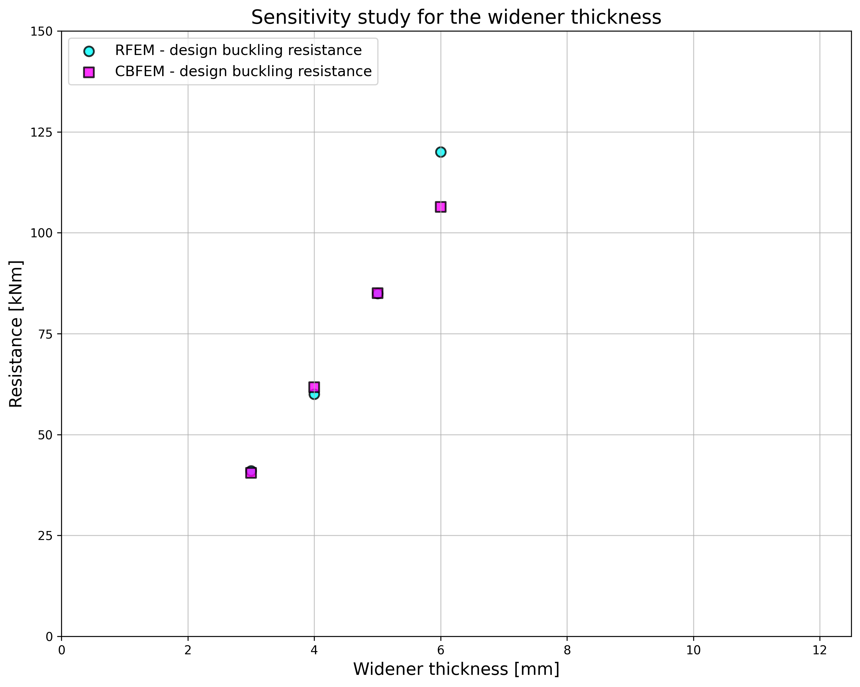
ความต้านทานการออกแบบที่คำนวณโดย CBFEM เปรียบเทียบกับผลที่ได้จาก RFEM การเปรียบเทียบมุ่งเน้นที่ความต้านทานการออกแบบและแรงวิกฤต ผลลัพธ์เรียงลำดับไว้ใน Tab. 6.1.4 แผนภาพใน Fig. 6.1.7 c) แสดงอิทธิพลของความหนาของแผ่นขยายต่อความต้านทานและแรงวิกฤตในตัวอย่างที่ตรวจสอบ
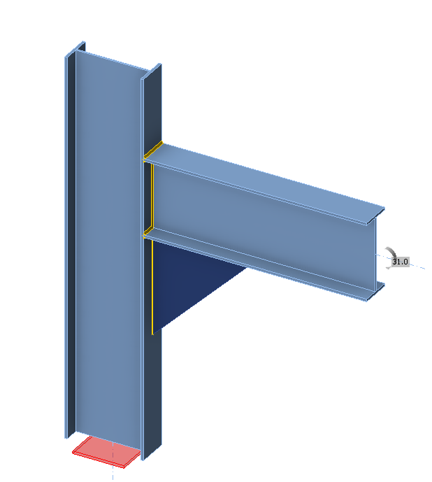
ผลลัพธ์แสดงความสอดคล้องกันเป็นอย่างดีในแรงวิกฤตและความต้านทานการออกแบบ สำรองหลังการโก่งเดาะสังเกตได้สำหรับเอวคานและแผ่นขยายรูปสามเหลี่ยมที่มีความหนา 3 และ 4 มม. แบบจำลอง CBFEM ของจุดต่อที่มีส่วนเสริมคานความหนา 3 มม. แสดงใน Fig. 6.1.7 a) รูปแบบการโก่งเดาะแรกสุดของจุดต่อแสดงใน Fig. 6.1.7 b)
Tab. 6.1.4 ความต้านทานการออกแบบ

การศึกษาการตรวจสอบยืนยันความถูกต้องของแบบจำลอง CBFEM สำหรับการทำนายพฤติกรรมของส่วนเสริมคานรูปสามเหลี่ยม ผลลัพธ์ของ CBFEM เปรียบเทียบกับผลลัพธ์ของ RFEM ขั้นตอนการออกแบบได้รับการตรวจสอบบนแบบจำลอง RFEM ซึ่งได้รับการยืนยันความถูกต้องจากการทดลอง ทุกขั้นตอนทำนายพฤติกรรมโดยรวมของจุดต่อในลักษณะที่คล้ายคลึงกัน
ตัวอย่าง Benchmark
ข้อมูลนำเข้า
คานและเสา
• เหล็ก S355
• ความหนาปีก tf = 10 มม.
• ความกว้างปีก bf = 120 มม.
• ความหนาเอว tw = 3 มม.
• ความสูงเอว hw = 300 มม.
ส่วนเสริมคานรูปสามเหลี่ยม
• ความหนา tw = 3 มม.
• ความกว้าง bw = 400 มม.
• ความสูง hw = 400 มม.
คำนวณ
• การวิเคราะห์การโก่งเดาะ
ผลลัพธ์
• ความต้านทานพลาสติก CBFEM = 138 kNm
• ความต้านทานการโก่งเดาะสำหรับการออกแบบ CBFEM = 41 kNm
• ตัวคูณการโก่งเดาะวิกฤต (สำหรับความต้านทานการโก่งเดาะสำหรับการออกแบบ CBFEM = 41 kNm) αcr = 0,52
• ตัวคูณแรงที่ความเครียดพลาสติก 5% αult,k = ความต้านทานพลาสติก CBFEM / ความต้านทานการโก่งเดาะสำหรับการออกแบบ CBFEM = 138 / 41 = 3,40
คำอธิบาย
วัตถุประสงค์ของการศึกษานี้คือการตรวจสอบความถูกต้องของวิธี Component-Based Finite Element (CBFEM) ของจุดต่อคาน-เสาที่มีแผ่นเอวเสาประเภท 4 กับวิธีส่วนประกอบ (CM)
แบบจำลองเชิงวิเคราะห์
ส่วนประกอบแผ่นเอวเสาในแรงเฉือนได้รับการอธิบายไว้ในข้อ 6.2.6.1 ของ EN 1993-1-8:2005 วิธีการออกแบบถูกจำกัดสำหรับความชะลูดของแผ่นเอวเสา d / tw ≤ 69 ε. แผ่นเอวที่มีความชะลูดสูงกว่าจะออกแบบตาม EN 1993-1-5:2006 ข้อ 5 และภาคผนวก A ความต้านทานแรงเฉือนประกอบด้วยความต้านทานการโก่งเดาะจากแรงเฉือนของแผ่นเอวและความต้านทานของโครงที่ประกอบด้วยปีกและแผ่นเสริมความแข็งที่ล้อมรอบแผ่นเอว ความต้านทานการโก่งเดาะของแผ่นเอวอ้างอิงจากความเค้นวิกฤตจากแรงเฉือน
โดยที่ σE คือความเค้นวิกฤต Euler ของแผ่น
สัมประสิทธิ์การโก่งเดาะ kτ ได้จาก EN 1993-1-5:2006 ภาคผนวก A.3
ความชะลูดของแผ่นเอวคือ
ตัวประกอบลดค่า χw สามารถหาได้จาก EN 1993-1-5:2006 ข้อ 5.3
ความต้านทานการโก่งเดาะจากแรงเฉือนของแผ่นเอวคือ
ความต้านทานของโครงสามารถออกแบบได้ตามข้อ 6.2.6.1 ใน EN 1993-1-8:2005
แบบจำลอง Finite Element สำหรับการออกแบบ
ขั้นตอนการออกแบบสำหรับแผ่นบางได้รับการอธิบายในหัวข้อ 3.10 การวิเคราะห์การโก่งเดาะเชิงเส้นถูกนำไปใช้ในซอฟต์แวร์ การคำนวณค่าความต้านทานการออกแบบดำเนินการตามขั้นตอนการออกแบบ FCBFEM ถูกประมาณค่าโดยผู้ใช้จนกว่า ρ ∙ αult,k/γM1 มีค่าเท่ากับ 1
ทำการศึกษาจุดต่อคาน-เสาที่มีแผ่นเอวเสาบาง ความสูงของแผ่นเอวคานมีการเปลี่ยนแปลง ดังนั้นความกว้างของแผ่นเอวเสาจึงเปลี่ยนแปลงด้วย รูปทรงเรขาคณิตของตัวอย่างได้รับการอธิบายในตาราง 6.2.1 จุดต่อรับโมเมนต์ดัด
ตาราง 6.2.1 ภาพรวมตัวอย่าง
| ตัวอย่าง | ปีกเสา | แผ่นเอวเสา | คาน | วัสดุ | ||
| bf | tf | hw | tw | IPE | ||
| [mm] | [mm] | [mm] | [mm] | |||
| IPE400 | 250 | 10 | 820 | 4 | 400 | S235 |
| IPE 450 | 250 | 10 | 820 | 4 | 450 | S235 |
| IPE500 | 250 | 10 | 820 | 4 | 500 | S235 |
| IPE 550 | 250 | 10 | 820 | 4 | 550 | S235 |
| IPE600 | 250 | 10 | 820 | 4 | 600 | S235 |
พฤติกรรมโดยรวมและการตรวจสอบ
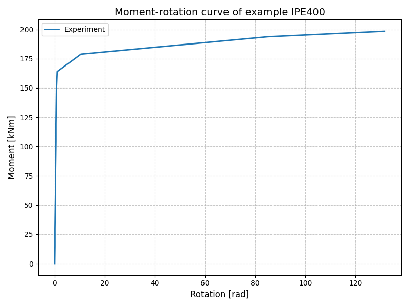
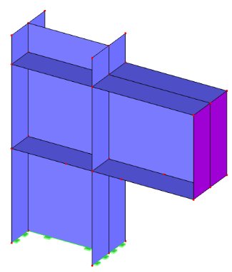
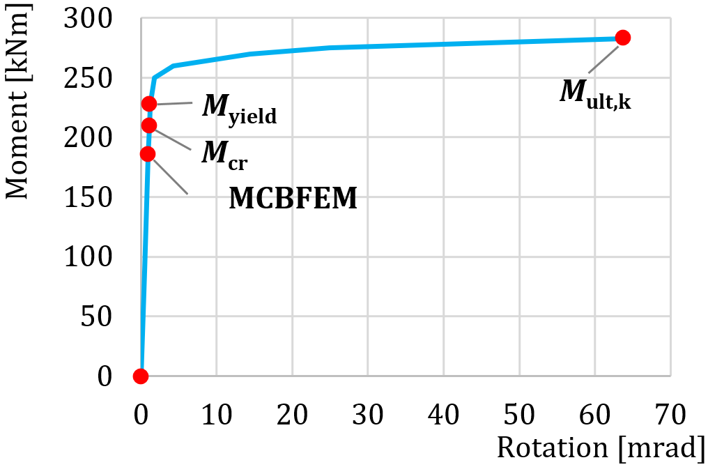
พฤติกรรมโดยรวมของจุดต่อคาน-เสาที่มีแผ่นเอวเสาบางซึ่งอธิบายด้วยแผนภาพโมเมนต์-การหมุนในแบบจำลอง CBFEM แสดงในรูปที่ 6.2.2 ให้ความสนใจกับลักษณะสำคัญ ได้แก่ ความต้านทานการออกแบบและแรงกระทำวิกฤต แผนภาพได้รับการเพิ่มเติมด้วยจุดที่การครากเริ่มต้นและความต้านทานที่ความเครียดพลาสติก 5%
การตรวจสอบความต้านทาน
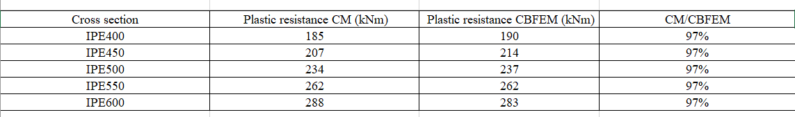
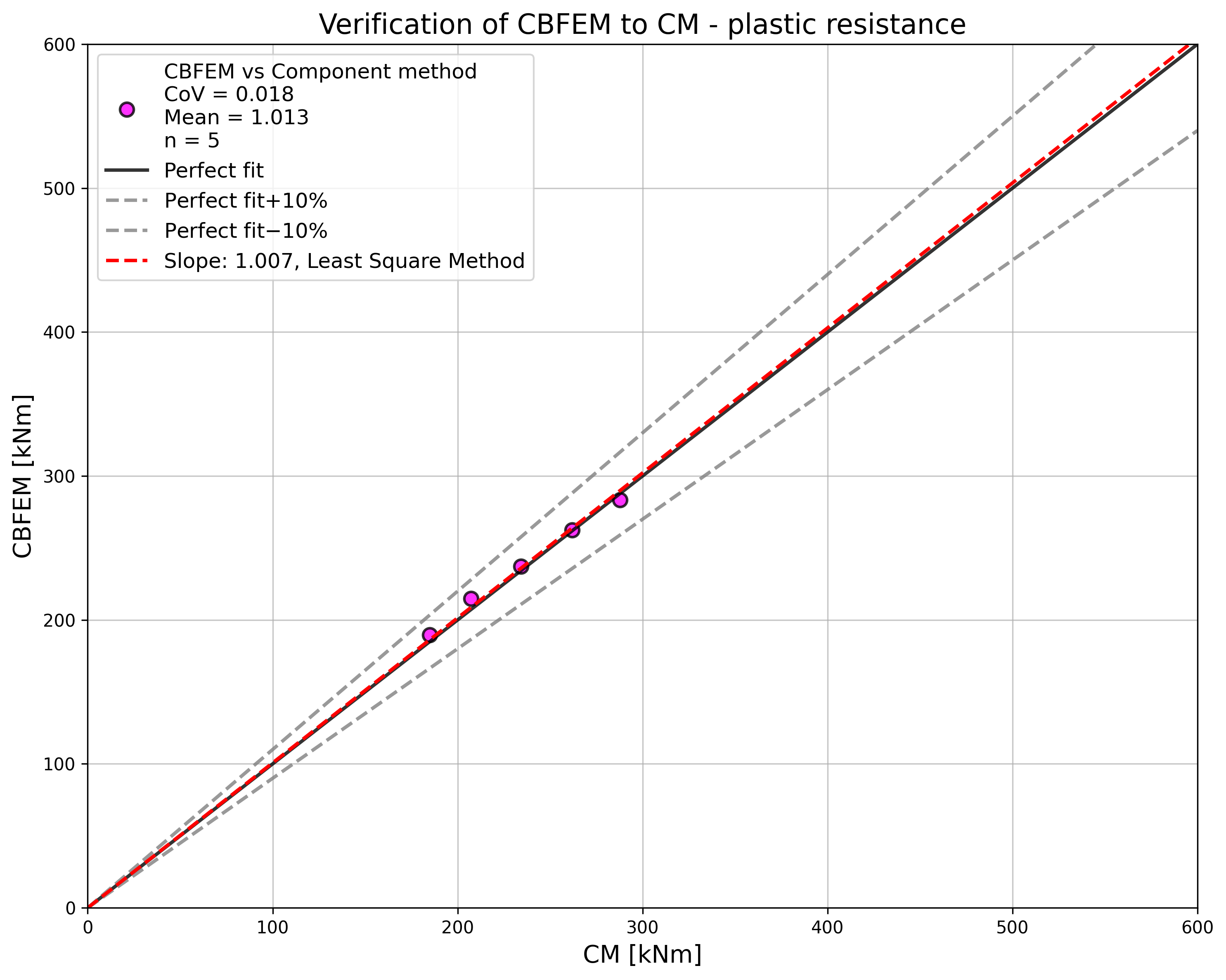
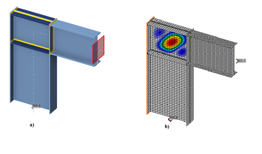
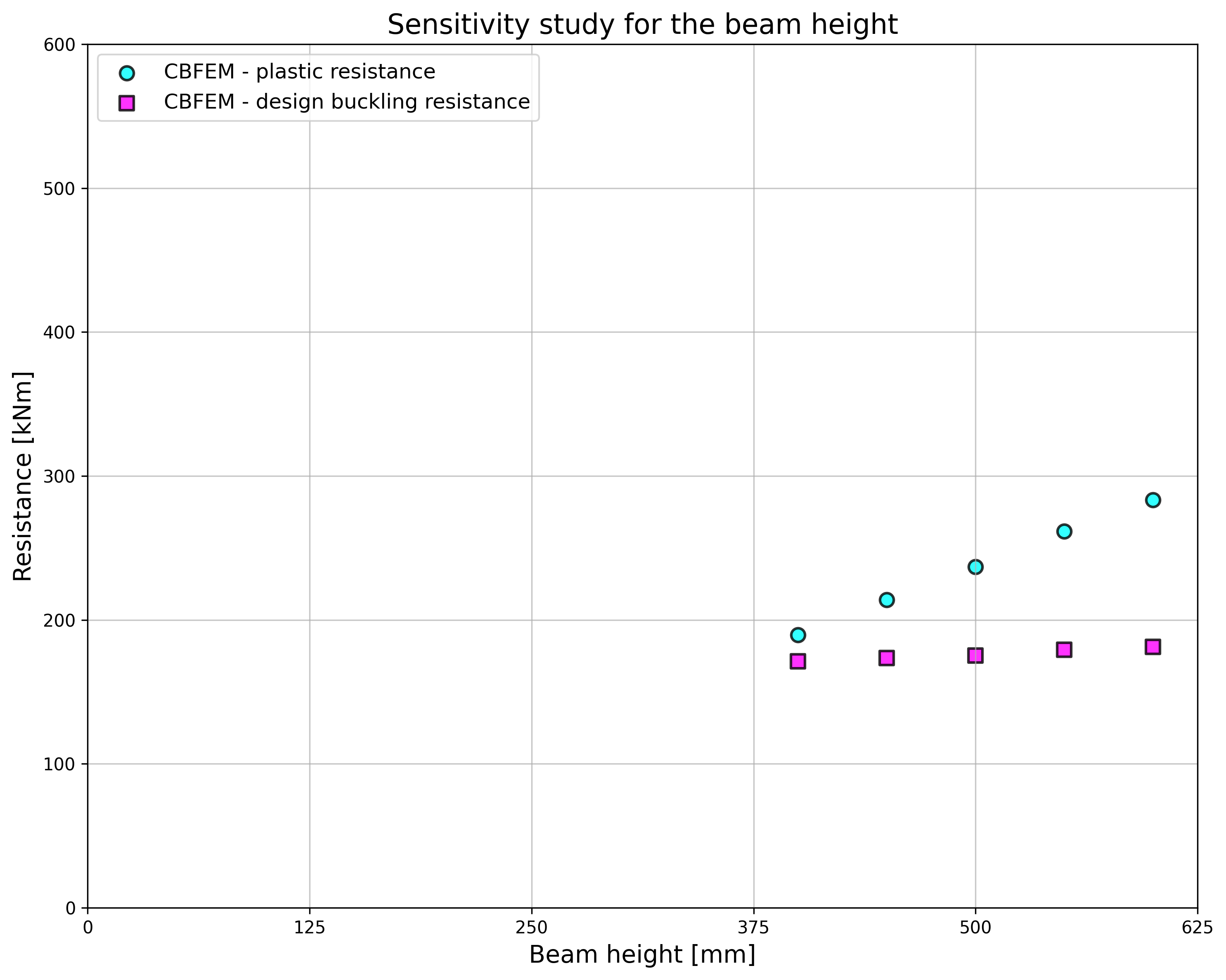
ความต้านทานการออกแบบที่คำนวณโดย CBFEM ถูกเปรียบเทียบกับ CM การเปรียบเทียบมุ่งเน้นที่ความต้านทานพลาสติก ผลลัพธ์ถูกจัดเรียงในตาราง 6.2.2a รูปที่ 6.2.2a แสดงความแตกต่างระหว่างวิธีการคำนวณทั้งสอง ตาราง 6.2.2b แสดงข้อมูลความต้านทานการโก่งเดาะสำหรับการออกแบบ ตาราง 6.2.2c และรูปที่ 6.2.3c แสดงความแตกต่างระหว่างวิธีการคำนวณทั้งสองเมื่อคำนวณความต้านทานการโก่งเดาะ แผนภาพในรูปที่ 6.2.3c แสดงอิทธิพลของความสูงหน้าตัดคานต่อความต้านทานและแรงกระทำวิกฤตในตัวอย่างที่ตรวจสอบ
ตาราง 6.2.2a ความต้านทานพลาสติกของ CM และ CBFEM
ตาราง 6.2.2b ความต้านทานการโก่งเดาะสำหรับการออกแบบ

ตาราง 6.2.2c ความต้านทานการโก่งเดาะของ CM และ CBFEM
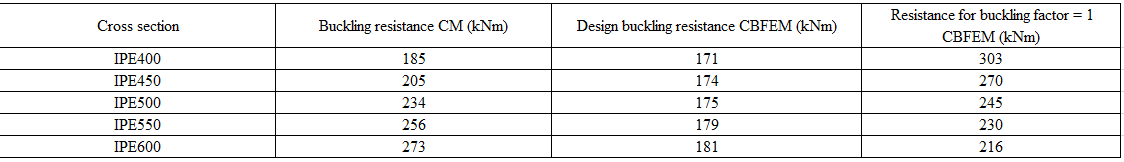
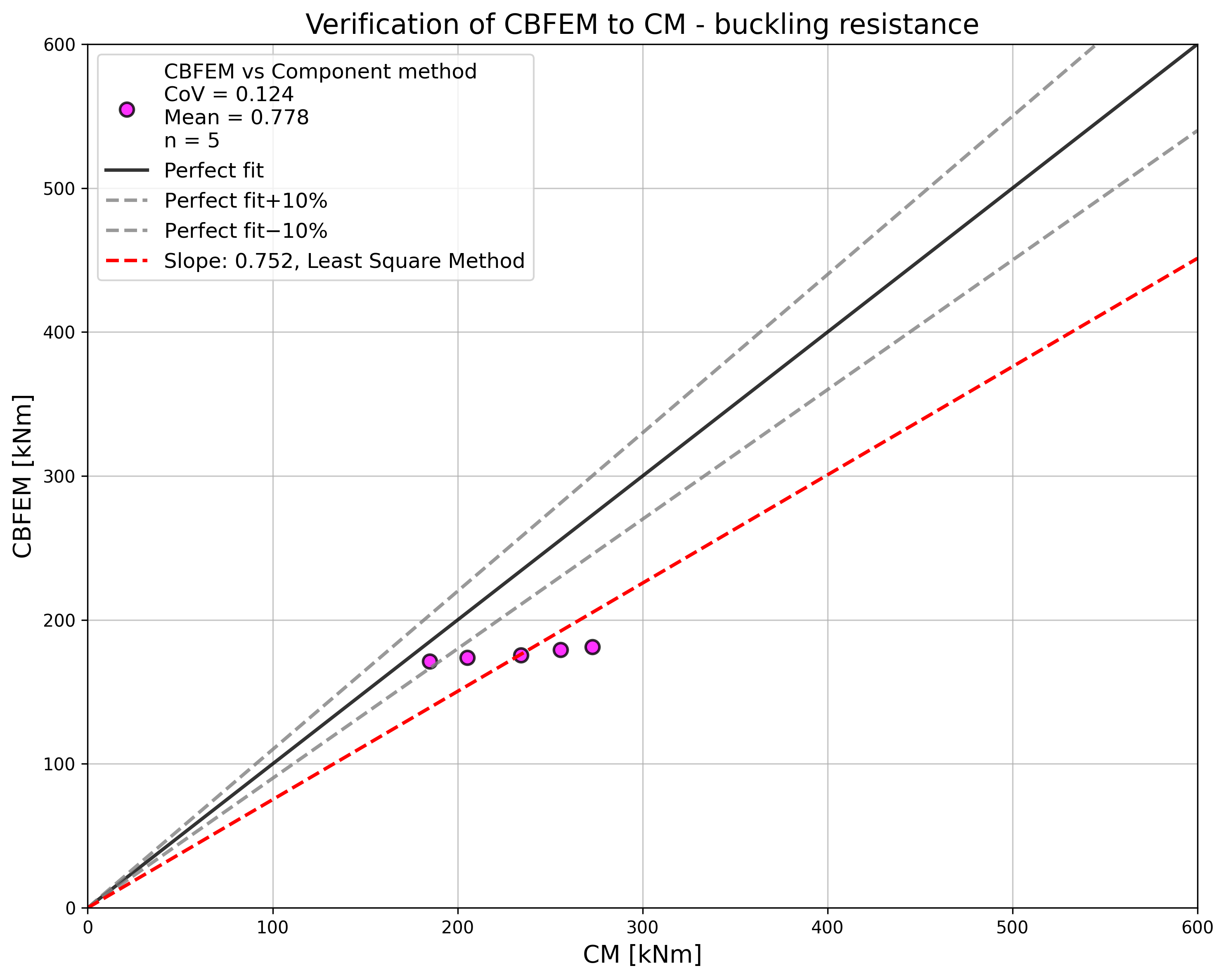
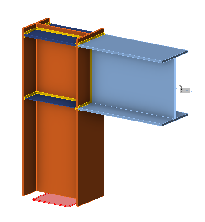
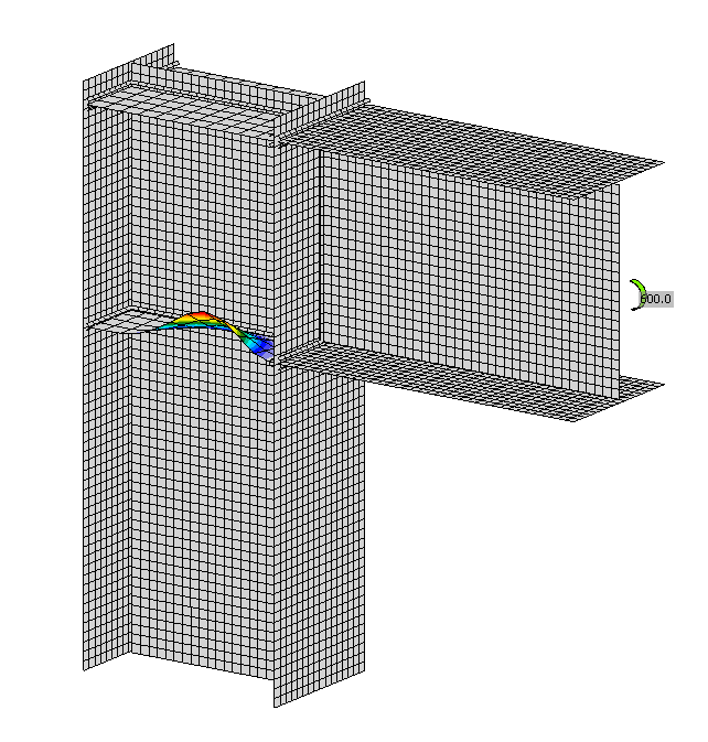
ผลลัพธ์แสดงให้เห็นความสอดคล้องที่ดีในแรงกระทำวิกฤตและความต้านทานการออกแบบ แบบจำลอง CBFEM ของจุดต่อที่มีคาน IPE600 แสดงในรูปที่ 6.2.3a รูปแบบการโก่งเดาะแรกของจุดต่อแสดงในรูปที่ 6.2.3b
การศึกษาการตรวจสอบยืนยันความถูกต้องของแบบจำลอง CBFEM สำหรับการทำนายพฤติกรรมของแผ่นเอวเสา ผลลัพธ์ของ CBFEM ถูกเปรียบเทียบกับผลลัพธ์ของ CM ขั้นตอนทั้งสองทำนายพฤติกรรมโดยรวมของจุดต่อได้ใกล้เคียงกัน
ตัวอย่าง Benchmark
ข้อมูลนำเข้า
คาน
- เหล็ก S235
- IPE600
เสา
- เหล็ก S235
- ความหนาปีก tf = 10 mm
- ความกว้างปีก bf = 250 mm
- ความหนาแผ่นเอว tw = 4 mm
- ความสูงแผ่นเอว hw = 800 mm
- ความสูงหน้าตัด h = 820 mm
- ส่วนที่ยื่นเกินด้านบนของคาน 20 mm
แผ่นเสริมความแข็งแผ่นเอว
- เหล็ก S235
- ความหนาแผ่นเสริมความแข็ง tw = 19 mm
- ความกว้างแผ่นเสริมความแข็ง hw = 250 mm
- รอยเชื่อม aw,stiff = 10 mm
- แผ่นเสริมความแข็งตรงข้ามกับปีกบนและปีกล่าง
การตั้งค่ามาตรฐาน – แบบจำลองและตาข่าย
- จำนวนองค์ประกอบบนแผ่นเอวหรือปีกของชิ้นส่วนที่ใหญ่ที่สุด 24
ผลลัพธ์
- แรงกระทำที่ความเครียดพลาสติก 5% Mult,k = 283 kNm
- ความต้านทานการออกแบบ MCBFEM = 181 kNm
- ตัวประกอบการโก่งเดาะวิกฤต (สำหรับ M = 189 kNm) αcr = 1,19
- ตัวประกอบแรงกระทำที่ความเครียดพลาสติก 5% αult,k = Mult,k / MCBFEM = 283/181 = 1,56
เอกสารอ้างอิง
EN 1993-1-5, Eurocode 3, Design of steel structures – Part 1-5: Plated Structural Elements, CEN, Brussels, 2005.
EN 1993-1-8, Eurocode 3, Design of steel structures – Part 1-8: Design of joints, CEN, Brussels, 2005.
Kuříková M., Wald F., Kabeláč J. Design of slender compressed plates in structural steel joints by component based finite element method, in SDSS 2019: International Colloquium on Stability and Ductility of Steel Structures, Prague, 2019.
คำอธิบาย
วัตถุประสงค์ของการศึกษานี้คือการตรวจสอบวิธี Component-Based Finite Element (CBFEM) สำหรับแผ่นเสริมความแข็งเอวเสาชั้น 4 ในจุดต่อคาน-เสา โดยเปรียบเทียบกับแบบจำลอง FEA เพื่อการวิจัย (RFEM) ที่สร้างในซอฟต์แวร์ Dlubal RFEM และวิธีส่วนประกอบ (CM)
แบบจำลอง FEA เพื่อการวิจัย
แบบจำลอง FEA เพื่อการวิจัย (RFEM) ใช้สำหรับตรวจสอบแบบจำลอง CBFEM ในแบบจำลองเชิงตัวเลข ใช้องค์ประกอบเปลือก 4 Node รูปสี่เหลี่ยมด้านขนานที่มี Node อยู่ที่มุม ใช้การวิเคราะห์แบบไม่เชิงเส้นทางเรขาคณิตและวัสดุพร้อมความไม่สมบูรณ์ (GMNIA) ความไม่สมบูรณ์ทางเรขาคณิตสมมูลได้มาจากรูปแบบการโก่งเดาะแรก และกำหนดแอมพลิจูดตาม Annex C ใน EN 1993-1-5:2006 แบบจำลองเชิงตัวเลขแสดงในรูปที่ 6.3.1
CBFEM
ขั้นตอนการออกแบบสำหรับแผ่นบางอธิบายไว้ในหัวข้อ 3.10 การวิเคราะห์การโก่งเดาะเชิงเส้นถูกนำไปใช้ในซอฟต์แวร์ การคำนวณค่าความต้านทานการออกแบบดำเนินการตามขั้นตอนการออกแบบ FCBFEM ถูกประมาณค่าโดยผู้ใช้จนกว่า ρ ∙ αult,k/γM1 มีค่าเท่ากับ 1 ศึกษาจุดต่อคาน-เสาที่มีแผ่นเสริมความแข็งเอวเสาแบบบาง ใช้หน้าตัดเดียวกันสำหรับคานและเสา ความหนาของแผ่นเสริมความแข็งเอวเสามีการเปลี่ยนแปลง เรขาคณิตของตัวอย่างอธิบายไว้ในตารางที่ 6.3.1 จุดต่อรับโมเมนต์ดัด
ตารางที่ 6.3.1 ภาพรวมตัวอย่าง
| ตัวอย่าง | ปีกเสา/คาน | เอวเสา/คาน | แผ่นเสริมความแข็ง | วัสดุ | ||
| bf | tf | hw | tw | ts | ||
| [mm] | [mm] | [mm] | [mm] | [mm] | ||
| t3 | 400 | 20 | 600 | 12 | 3 | S235 |
| t4 | 400 | 20 | 600 | 12 | 4 | S235 |
| t5 | 400 | 20 | 600 | 12 | 5 | S235 |
| t6 | 400 | 20 | 600 | 12 | 6 | S235 |
พฤติกรรมโดยรวมและการตรวจสอบ
พฤติกรรมโดยรวมของจุดต่อคาน-เสาที่มีแผ่นเสริมความแข็งเอวเสาแบบบาง ความหนา 3 มม. ที่อธิบายด้วยแผนภาพโมเมนต์-การหมุนในแบบจำลอง CBFEM แสดงในรูปที่ 6.3.2 ให้ความสนใจกับลักษณะสำคัญ ได้แก่ ความต้านทานการออกแบบและแรงกระทำวิกฤต แผนภาพเสร็จสมบูรณ์ด้วยจุดที่การครากเริ่มต้นและความต้านทานที่ความเครียดพลาสติก 5%
การตรวจสอบความต้านทาน
ความต้านทานการออกแบบที่คำนวณโดยซอฟต์แวร์ CBFEM IDEA StatiCa ถูกเปรียบเทียบกับ RFEM การเปรียบเทียบมุ่งเน้นที่ความต้านทานการออกแบบและแรงกระทำวิกฤต ผลลัพธ์เรียงลำดับในตารางที่ 6.3.2 แผนภาพในรูปที่ 6.3.3 c) แสดงอิทธิพลของความหนาของแผ่นเสริมความแข็งเอวเสาต่อความต้านทานและแรงกระทำวิกฤตในตัวอย่างที่ตรวจสอบ
ตารางที่ 6.3.2 ความต้านทานการออกแบบและแรงกระทำวิกฤตของ RFEM และ CBFEM

ผลลัพธ์แสดงความสอดคล้องที่ดีมากในแรงกระทำวิกฤตและความต้านทานการออกแบบ แบบจำลอง CBFEM ของจุดต่อที่มีแผ่นเสริมความแข็งเอวความหนา 3 มม. แสดงในรูปที่ 6.3.3a รูปแบบการโก่งเดาะแรกของจุดต่อแสดงในรูปที่ 6.3.3b
การศึกษาตรวจสอบยืนยันความถูกต้องของแบบจำลอง CBFEM สำหรับการทำนายพฤติกรรมของแผ่นเสริมความแข็งเอวเสา ผลลัพธ์ของ CBFEM ถูกเปรียบเทียบกับผลลัพธ์ของ RFEM ทุกขั้นตอนทำนายพฤติกรรมโดยรวมของจุดต่อที่คล้ายกัน ความแตกต่างในความต้านทานการออกแบบในทุกกรณีต่ำกว่า 10%
ตัวอย่าง Benchmark
ข้อมูลนำเข้า
คาน
- เหล็ก S235
- ความหนาปีก tf = 20 มม.
- ความกว้างปีก bf = 400 มม.
- ความหนาเอว tw = 12 มม.
- ความสูงเอว hw = 600 มม.
เสา
- เหล็ก S235
- ความหนาปีก tf = 20 มม.
- ความกว้างปีก bf = 400 มม.
- ความหนาเอว tw = 12 มม.
- ความสูงเอว hw = 560 มม.
- ความสูงหน้าตัด h = 600 มม.
แผ่นเสริมความแข็งเอวเสาด้านบน
- เหล็ก S235
- ความหนาแผ่นเสริมความแข็ง tw = 20 มม.
- ความกว้างแผ่นเสริมความแข็ง hw = 400 มม.
แผ่นเสริมความแข็งเอวเสาด้านล่าง
- เหล็ก S235
- ความหนาแผ่นเสริมความแข็ง tw = 3 มม.
- ความกว้างแผ่นเสริมความแข็ง hw = 400 มม.
การตั้งค่ามาตรฐาน – แบบจำลองและตาข่าย
- จำนวนองค์ประกอบบนเอวหรือปีกของชิ้นส่วนที่ใหญ่ที่สุด 24
ผลลัพธ์
- ความต้านทานพลาสติก CBFEM = 589 kNm
- ความต้านทานการโก่งเดาะการออกแบบ CBFEM (kNm) = 309 kNm
- ตัวประกอบการโก่งเดาะวิกฤต (สำหรับความต้านทานการโก่งเดาะการออกแบบ = 309 kNm) αcr = 0,97
- ตัวประกอบแรงกระทำที่ความเครียดพลาสติก 5% αult,k = ความต้านทานพลาสติก CBFEM / ความต้านทานการโก่งเดาะการออกแบบ CBFEM = 589/309 = 1,91
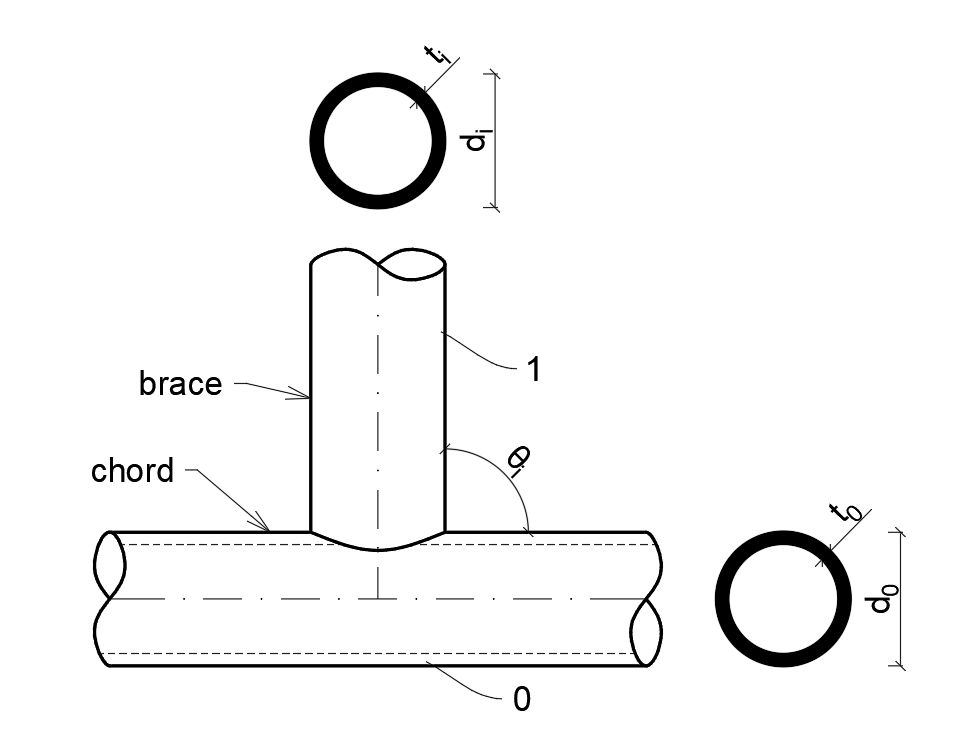
จุดต่อหน้าตัดกลวง
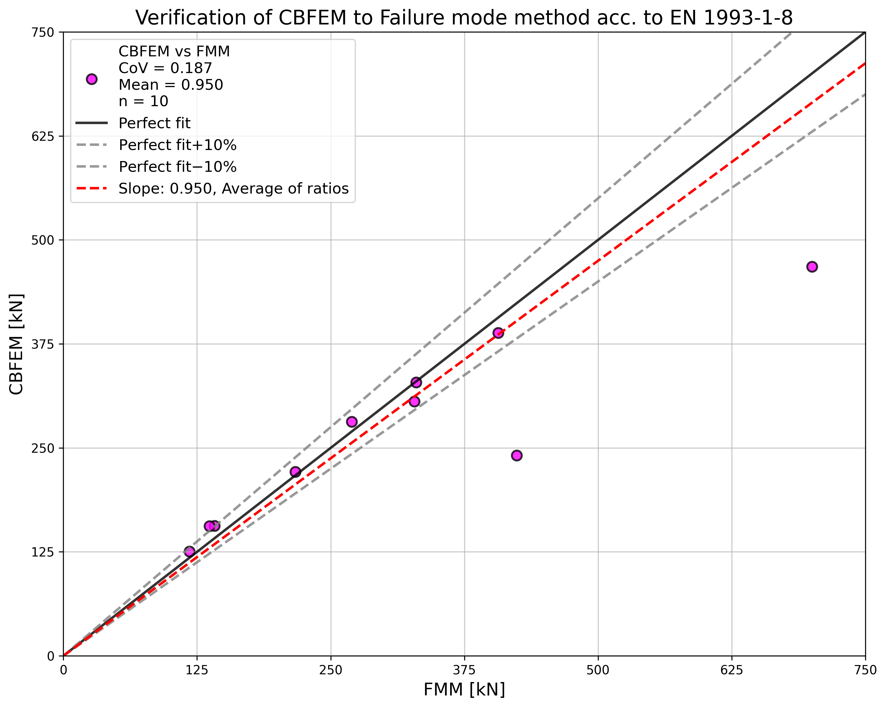
วิธีรูปแบบการวิบัติ
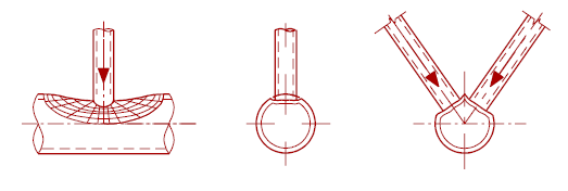
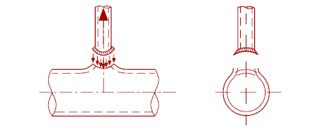
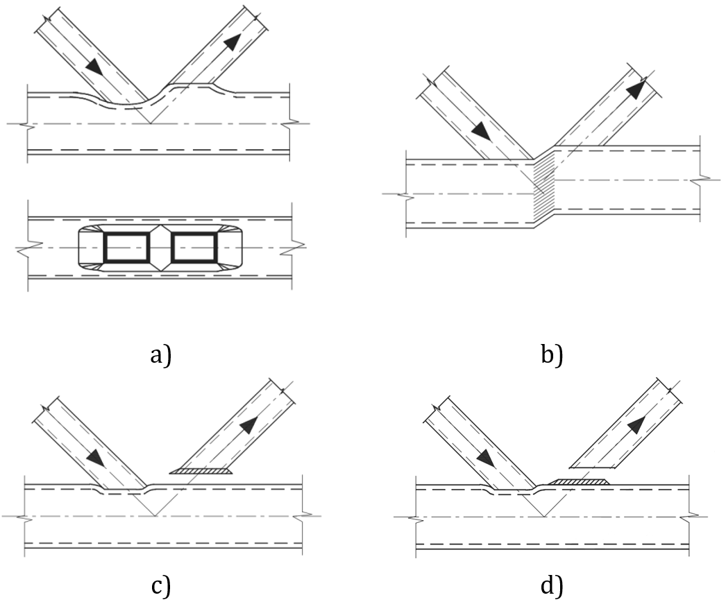
ในบทนี้ วิธี Component-Based Finite Element (CBFEM) สำหรับการออกแบบการเชื่อมต่อโครงสร้างเหล็กส่วนตัดกลวงทรงกระบอก (CHS) แบบระนาบเดียวที่เชื่อมด้วยการเชื่อม ได้รับการตรวจสอบความถูกต้องเทียบกับวิธีรูปแบบการวิบัติ (FMM): จุดต่อแบบ T, X และ K ใน CBFEM ความต้านทานการออกแบบถูกจำกัดโดยการถึงค่าความเครียด 5% หรือแรงที่สอดคล้องกับการเสียรูปของจุดต่อ 3% d0 โดยที่ d0 คือเส้นผ่านศูนย์กลางของ chord ความต้านทานใน FMM โดยทั่วไปถูกกำหนดโดยแรงสูงสุดหรือขีดจำกัดการเสียรูป 3% d0 ดู (Lu et al. 1994) FMM อยู่บนหลักการของการระบุรูปแบบที่อาจทำให้จุดต่อวิบัติ จากประสบการณ์เชิงปฏิบัติและการทดลองที่ดำเนินการในช่วงทศวรรษ 1970 และ 1980 มีการระบุรูปแบบการวิบัติสองรูปแบบสำหรับจุดต่อ CHS ได้แก่ การเกิดพลาสติกของ chord และแรงเฉือนทะลุ chord วิธีการคำนวณนี้ถูกจำกัดเสมอสำหรับรูปทรงเรขาคณิตของจุดต่อที่ทดสอบ ซึ่งหมายความว่าสูตรที่แตกต่างกันจะใช้กับแต่ละรูปทรงเรขาคณิตเสมอ ในการศึกษาต่อไปนี้ รอยเชื่อมได้รับการออกแบบตาม EN 1993‑1‑8:2006 เพื่อไม่ให้เป็นองค์ประกอบที่อ่อนแอที่สุดในจุดต่อ
การเกิดพลาสติกของ Chord
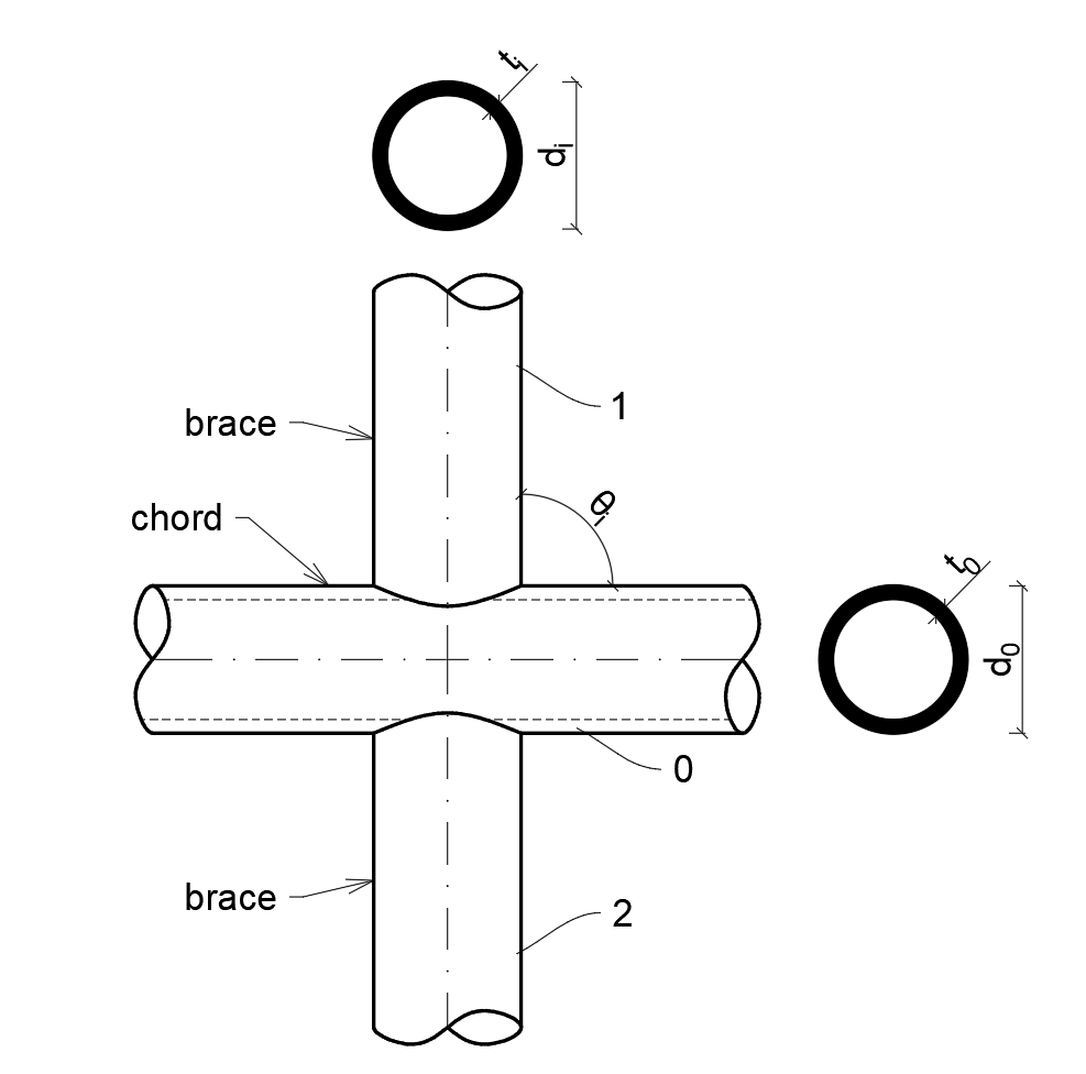
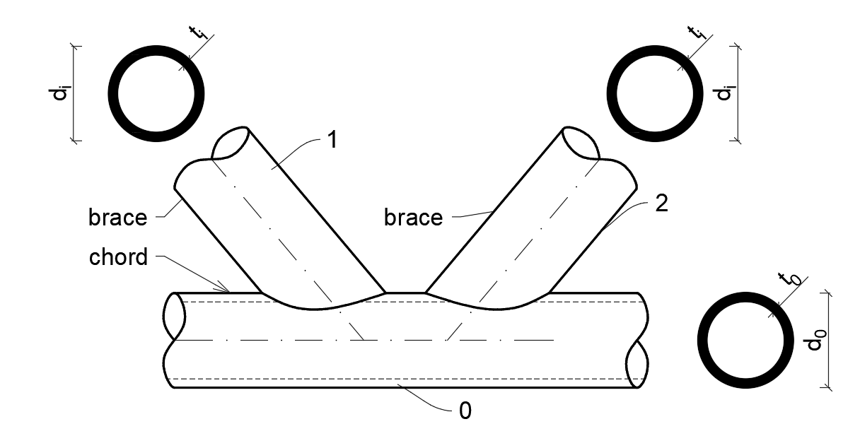
ความต้านทานการออกแบบของหน้า chord ของ CHS สามารถกำหนดได้โดยใช้วิธีที่ให้ไว้โดยแบบจำลอง FMM ใน Ch. 9 ของ prEN 1993-1-8:2020 ดู Fig. 7.1.1 วิธีนี้ยังให้ไว้ใน ISO/FDIS 14346 และอธิบายรายละเอียดเพิ่มเติมใน (Wardenier et al. 2010) ความต้านทานการออกแบบของจุดต่อ CHS ที่เชื่อมและรับแรงตามแนวแกนคือ:
- สำหรับจุดต่อแบบ T และ Y
- จุดต่อแบบ X
- และสำหรับจุดต่อแบบ K gap
โดยที่:
- di – เส้นผ่านศูนย์กลางรวมของชิ้นส่วน CHS i (i = 0, 1, 2 หรือ 3)
- fyi – กำลังคราก (yield strength) ของชิ้นส่วน i (i = 0, 1, 2 หรือ 3)
- g – ช่องว่างระหว่าง brace ของจุดต่อแบบ K
- ti – ความหนาของผนังชิ้นส่วน CHS i (i = 0, 1, 2 หรือ 3)
- – มุมระหว่างชิ้นส่วน brace i และ chord (i =1, 2 หรือ 3)
- – อัตราส่วนของเส้นผ่านศูนย์กลางเฉลี่ยหรือความกว้างของชิ้นส่วน brace ต่อของ chord
- – อัตราส่วนของความกว้างหรือเส้นผ่านศูนย์กลางของ chord ต่อสองเท่าของความหนาผนัง
- Qf – ตัวประกอบความเค้นของ chord
- Cf – ตัวประกอบวัสดุ
- – ตัวประกอบความปลอดภัยบางส่วนสำหรับความต้านทานของจุดต่อในคานโครงถักส่วนตัดกลวง
- Ni,Rd – ค่าการออกแบบความต้านทานของจุดต่อที่แสดงในรูปของแรงตามแนวแกนภายในของชิ้นส่วน i (i = 0, 1, 2 หรือ 3)
แรงเฉือนทะลุ Chord
(สำหรับ )
ความต้านทานการออกแบบของจุดต่อแบบ T, Y, X และ K ที่รับแรงตามแนวแกนของส่วนตัดกลวงทรงกระบอกที่เชื่อมสำหรับแรงเฉือนทะลุ chord (Fig. 7.1.2) คือ:
โดยที่:
- di – เส้นผ่านศูนย์กลางรวมของชิ้นส่วน CHS i (i = 0,1,2 หรือ 3)
- ti – ความหนาของผนังชิ้นส่วน CHS i (i = 0,1,2 หรือ 3)
- fy,i – กำลังคราก (yield strength) ของชิ้นส่วน i (i = 0,1,2 หรือ 3)
- – มุมระหว่างชิ้นส่วน brace i และ chord (i = 1,2 หรือ 3)
- Cf – ตัวประกอบวัสดุ
- Ni,Rd – ค่าการออกแบบความต้านทานของจุดต่อที่แสดงในรูปของแรงตามแนวแกนภายในของชิ้นส่วน i (i = 0, 1, 2 หรือ 3)
แรงเฉือนของ Chord
(สำหรับจุดต่อแบบ X เฉพาะเมื่อ )
ความต้านทานการออกแบบของจุดต่อแบบ X ที่รับแรงตามแนวแกนของส่วนตัดกลวงทรงกระบอกที่เชื่อมสำหรับแรงเฉือนของ chord ดู Fig. 7.1.3 คือ:
โดยที่:
- Ai – พื้นที่หน้าตัด i (i = 0,1,2 หรือ 3)
- fy,i – กำลังคราก (yield strength) ของชิ้นส่วน i (i = 0,1,2 หรือ 3)
- – มุมระหว่างชิ้นส่วน brace i และ chord (i = 1,2 หรือ 3)
- Ni,Rd – ค่าการออกแบบความต้านทานของจุดต่อที่แสดงในรูปของแรงตามแนวแกนภายในของชิ้นส่วน i (i = 0, 1, 2 หรือ 3)
ขอบเขตความถูกต้อง
CBFEM ได้รับการตรวจสอบความถูกต้องสำหรับจุดต่อทั่วไปของส่วนตัดกลวงทรงกระบอกที่เชื่อม ขอบเขตความถูกต้องสำหรับจุดต่อเหล่านี้ถูกกำหนดไว้ใน Table 7.1.8 ของ prEN 1993-1-8:2020 ดู Tab 7.1.2 ขอบเขตความถูกต้องเดียวกันนี้ถูกนำไปใช้กับแบบจำลอง CBFEM นอกขอบเขตความถูกต้องของ FMM ควรจัดเตรียมการทดลองเพื่อการตรวจสอบความถูกต้อง หรือดำเนินการตรวจสอบตามแบบจำลองการวิจัยที่ผ่านการตรวจสอบแล้ว
Tab. 7.1.2 ขอบเขตความถูกต้องสำหรับวิธีรูปแบบการวิบัติ
| ทั่วไป | |||
| Chord | แรงอัด | Class 1 หรือ 2 และ (แต่สำหรับจุดต่อแบบ X: ) |
| แรงดึง | (แต่สำหรับจุดต่อแบบ X: ) | |
| CHS braces | แรงอัด | Class 1 หรือ 2 และ |
| แรงดึง |
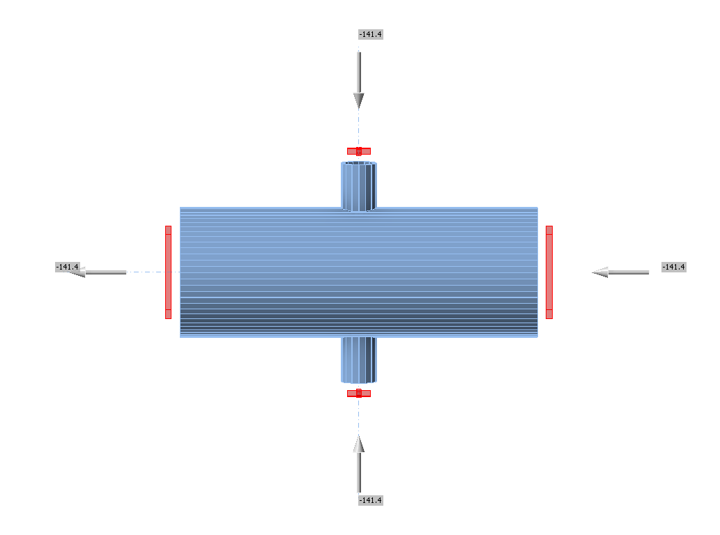
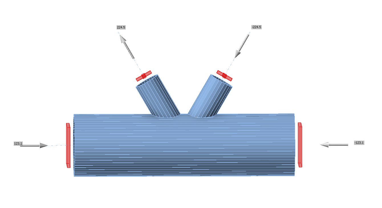
จุดต่อ CHS แบบ T และ Y ระนาบเดียว
ภาพรวมของตัวอย่างที่พิจารณาในการศึกษาแสดงไว้ใน Tab. 7.1.3 กรณีที่เลือกครอบคลุมช่วงกว้างของอัตราส่วนทางเรขาคณิตของจุดต่อ รูปทรงเรขาคณิตของจุดต่อพร้อมขนาดแสดงไว้ใน Fig. 7.1.2 ในกรณีที่เลือก จุดต่อวิบัติตาม FMM โดยการเกิดพลาสติกของ chord หรือแรงเฉือนทะลุ
Tab. 7.1.3 ภาพรวมตัวอย่าง
| ตัวอย่าง | Chord | Brace | มุม | วัสดุ | ||
| หน้าตัด | หน้าตัด | fy | fu | E | ||
| [°] | [MPa] | [MPa] | [GPa] | |||
| 1 | CHS219.1/5.0 | CHS48.3/5.0 | 90 | 355 | 490 | 210 |
| 2 | CHS219.1/5.0 | CHS114.3/6.3 | 90 | 355 | 490 | 210 |
| 3 | CHS219.1/6.3 | CHS114.3/6.3 | 90 | 355 | 490 | 210 |
| 4 | CHS219.1/10.0 | CHS60.3/5.0 | 90 | 355 | 490 | 210 |
| 5 | CHS219.1/12.5 | CHS168.3/10.0 | 90 | 355 | 490 | 210 |
| 6 | CHS219.1/8.0 | CHS48.3/5.0 | 90 | 355 | 490 | 210 |
การตรวจสอบความต้านทาน
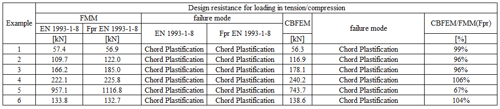
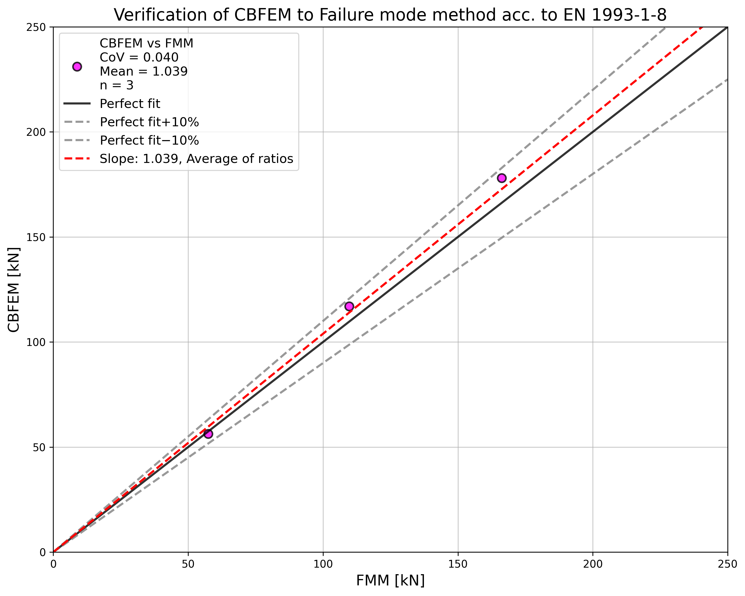
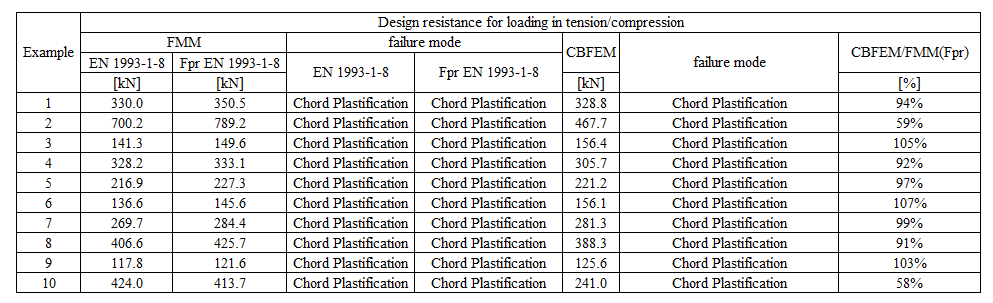
ผลลัพธ์ของวิธีที่อิงตาม FMM ถูกเปรียบเทียบกับผลลัพธ์ของ CBFEM การเปรียบเทียบมุ่งเน้นที่ความต้านทานและรูปแบบการวิบัติในการออกแบบ ผลลัพธ์แสดงไว้ใน Tab. 7.1.4
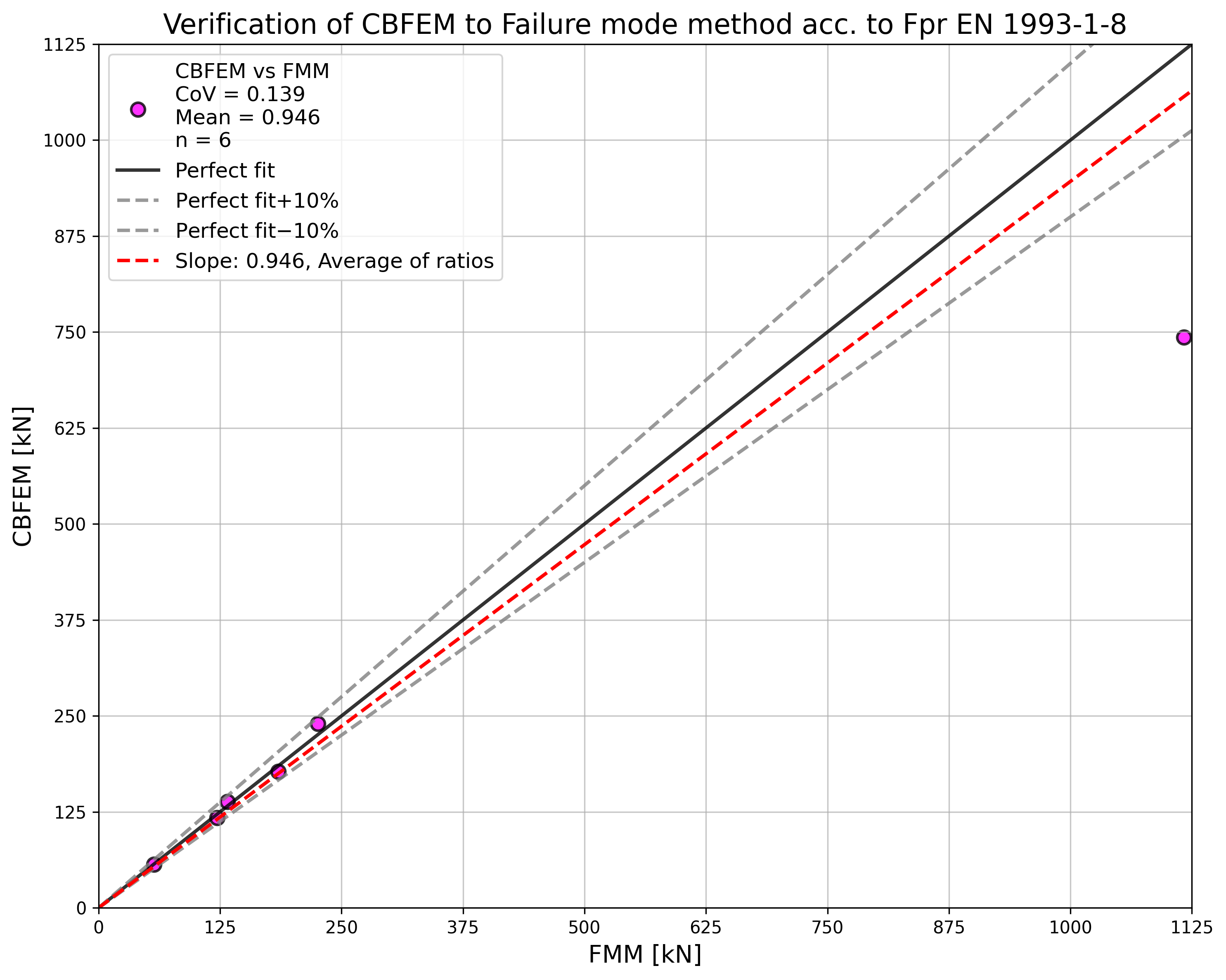
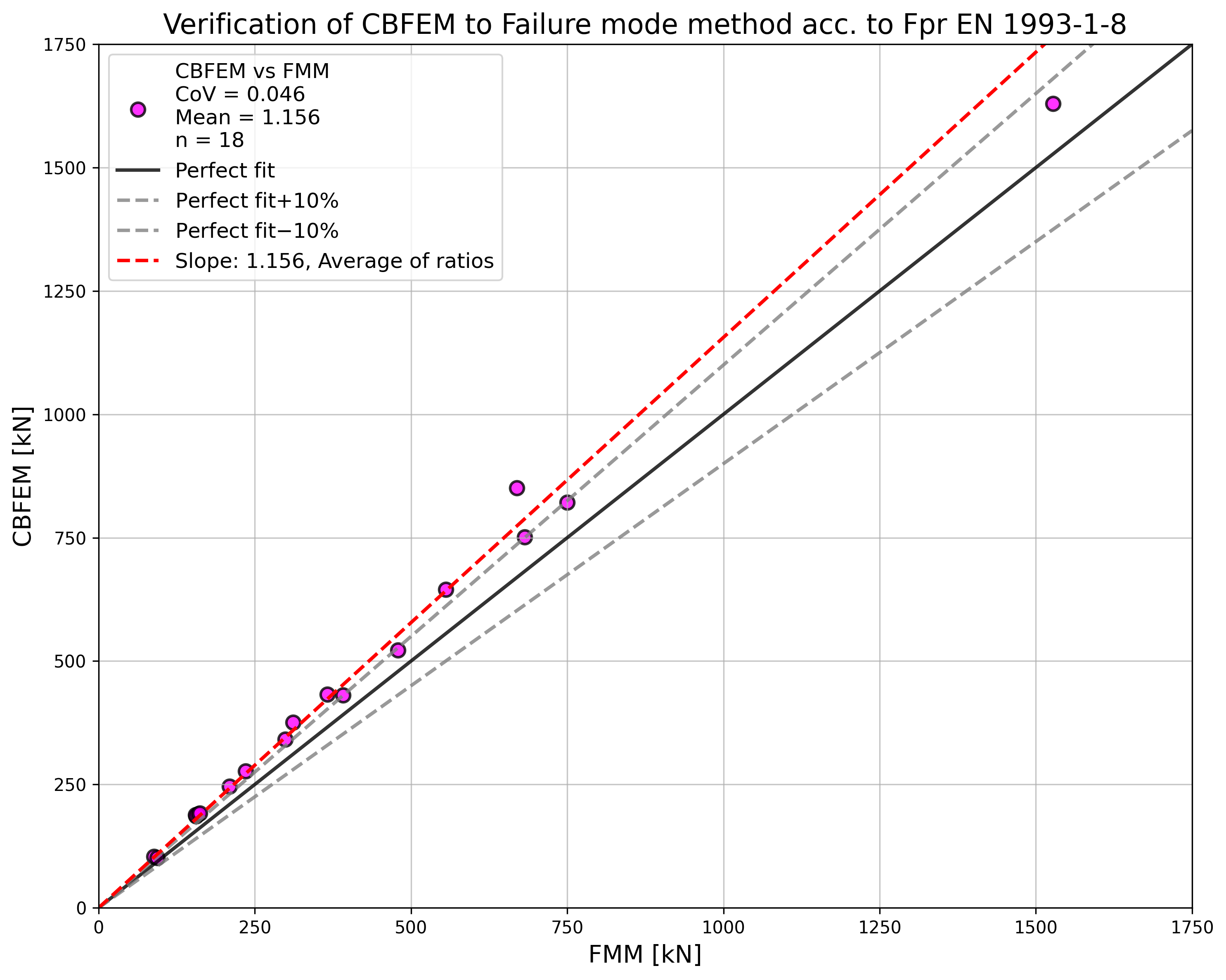
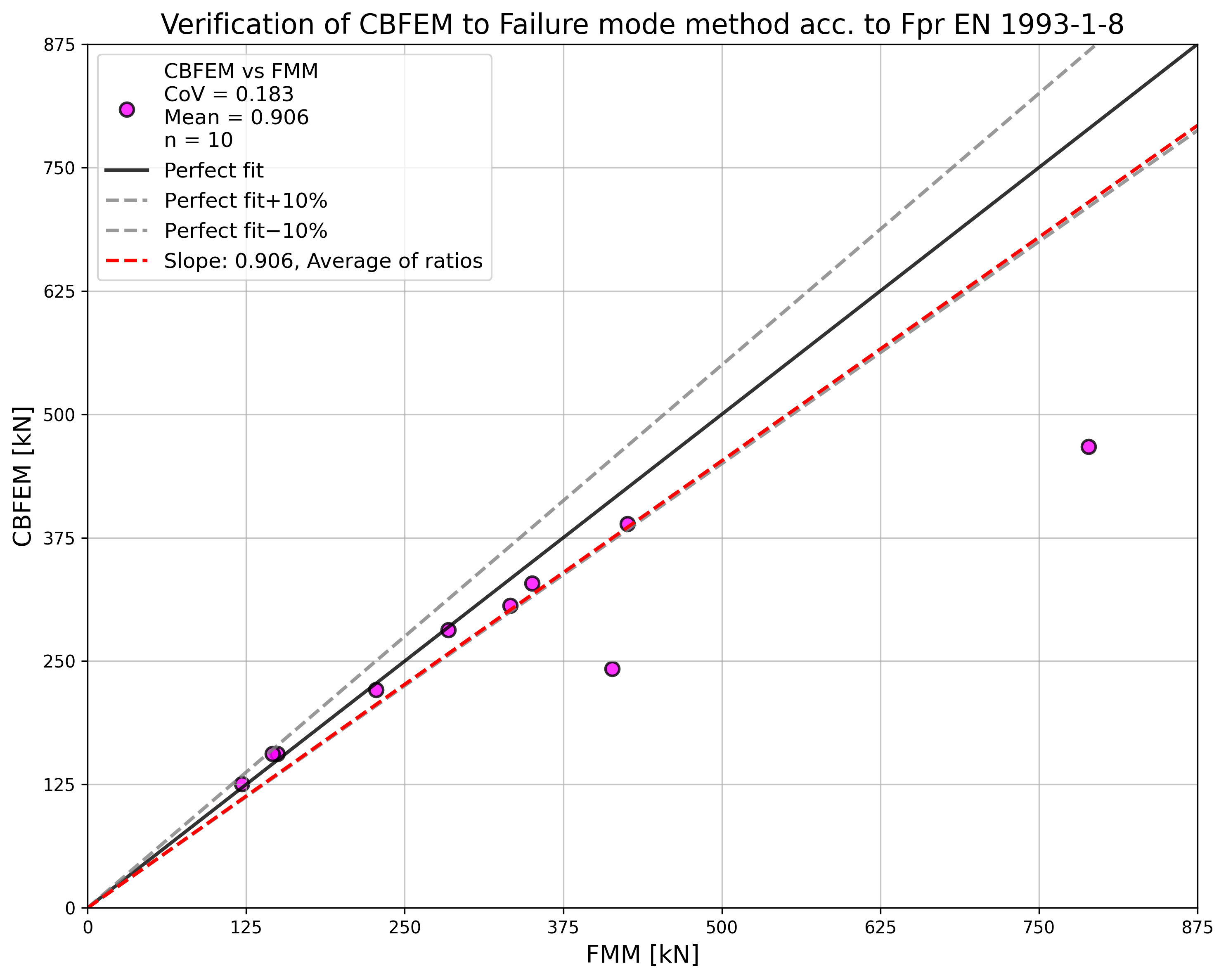
การศึกษาแสดงให้เห็นความสอดคล้องกันที่ดีสำหรับกรณีแรงกระทำที่ใช้ ผลลัพธ์ถูกสรุปในแผนภาพที่เปรียบเทียบค่าการออกแบบความต้านทานของ CBFEM และ FMM ดู Fig. 7.1.5 ผลลัพธ์แสดงให้เห็นว่าความแตกต่างระหว่างวิธีการคำนวณทั้งสองในทุกกรณีน้อยกว่า 14%
Tab. 7.1.4 การเปรียบเทียบค่าการออกแบบความต้านทานสำหรับการรับแรงดึง/แรงอัด: การทำนายโดย CBFEM และ FMM
ตัวอย่าง Benchmark
ข้อมูลนำเข้า
Chord
- เหล็ก S355
- หน้าตัด CHS219.1/5.0
Brace
- เหล็ก S355
- หน้าตัด CHS48.3/5.0
- มุมระหว่างชิ้นส่วน brace และ chord 90°
รอยเชื่อม
- รอยเชื่อมชนรอบ brace
การรับแรง
- โดยแรงกระทำต่อ brace ในแรงอัด
ขนาดตาข่าย
- 64 องค์ประกอบตามพื้นผิวของชิ้นส่วนกลวงทรงกระบอก
ผลลัพธ์
- ค่าการออกแบบความต้านทานในแรงอัดคือ NRd = 56.3 kN
- รูปแบบการวิบัติในการออกแบบคือการเกิดพลาสติกของ chord
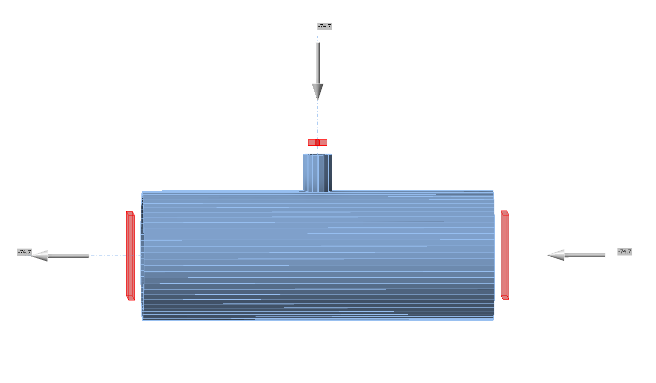
จุดต่อ CHS แบบ X ระนาบเดียว
ภาพรวมของตัวอย่างที่พิจารณาในการศึกษาแสดงไว้ใน Tab. 7.1.5 กรณีที่เลือกครอบคลุมช่วงกว้างของอัตราส่วนทางเรขาคณิตของจุดต่อ รูปทรงเรขาคณิตของจุดต่อพร้อมขนาดแสดงไว้ใน Fig. 7.1.6 ในกรณีที่เลือก จุดต่อวิบัติตาม FMM โดยการเกิดพลาสติกของ chord หรือแรงเฉือนทะลุ
Tab. 7.1.5 ภาพรวมตัวอย่าง
| ตัวอย่าง | Chord | Brace | มุม | วัสดุ | ||
| หน้าตัด | หน้าตัด | fy | fu | E | ||
| [°] | [MPa] | [MPa] | [GPa] | |||
| 1 | CHS219.1/6.3 | CHS60.3/5.0 | 90 | 355 | 490 | 210 |
| 2 | CHS219.1/8.0 | CHS76.1/5.0 | 90 | 355 | 490 | 210 |
| 3 | CHS219.1/10.0 | CHS139.7/10.0 | 90 | 355 | 490 | 210 |
| 4 | CHS219.1/12.5 | CHS114.3/6.3 | 90 | 355 | 490 | 210 |
| 5 | CHS219.1/10.0 | CHS76.1/5.0 | 90 | 355 | 490 | 210 |
| 6 | CHS219.1/8.0 | CHS114.3/6.3 | 90 | 355 | 490 | 210 |
| 7 | CHS219.1/6.3 | CHS48.3/5.0 | 60 | 355 | 490 | 210 |
| 8 | CHS219.1/6.3 | CHS114.3/6.3 | 60 | 355 | 490 | 210 |
| 9 | CHS219.1/8.0 | CHS60.3/5.0 | 60 | 355 | 490 | 210 |
| 10 | CHS219.1/10.0 | CHS114.3/6.3 | 60 | 355 | 490 | 210 |
| 11 | CHS219.1/12.5 | CHS139.7/10.0 | 60 | 355 | 490 | 210 |
| 12 | CHS219.1/8.0 | CHS139.7/10.0 | 60 | 355 | 490 | 210 |
| 13 | CHS219.1/6.3 | CHS48.3/5.0 | 30 | 355 | 490 | 210 |
| 14 | CHS219.1/6.3 | CHS193.7/12.5 | 30 | 355 | 490 | 210 |
| 15 | CHS219.1/6.3 | CHS219.1/12.5 | 30 | 355 | 490 | 210 |
| 16 | CHS219.1/8.0 | CHS76.1/5.0 | 30 | 355 | 490 | 210 |
| 17 | CHS219.1/8.0 | CHS168.3/10 | 30 | 355 | 490 | 210 |
| 18 | CHS219.1/12.5 | CHS168.3/10 | 30 | 355 | 490 | 210 |
การตรวจสอบความต้านทาน
ผลลัพธ์ของ CBFEM ถูกเปรียบเทียบกับผลลัพธ์ของ FMM การเปรียบเทียบมุ่งเน้นที่ความต้านทานและรูปแบบการวิบัติในการออกแบบ ผลลัพธ์แสดงไว้ใน Tab. 7.1.6
Tab. 7.1.6 การเปรียบเทียบผลลัพธ์การทำนายโดย CBFEM และ FMM
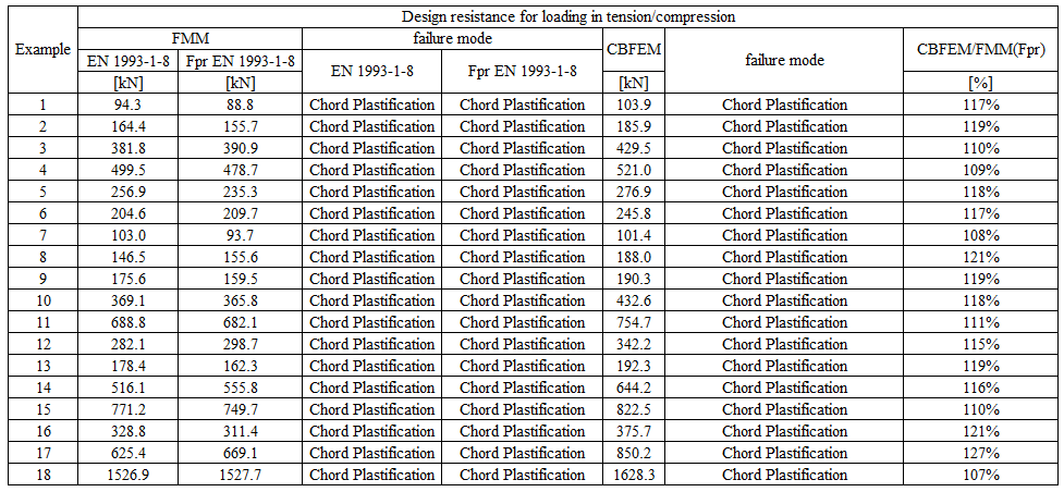
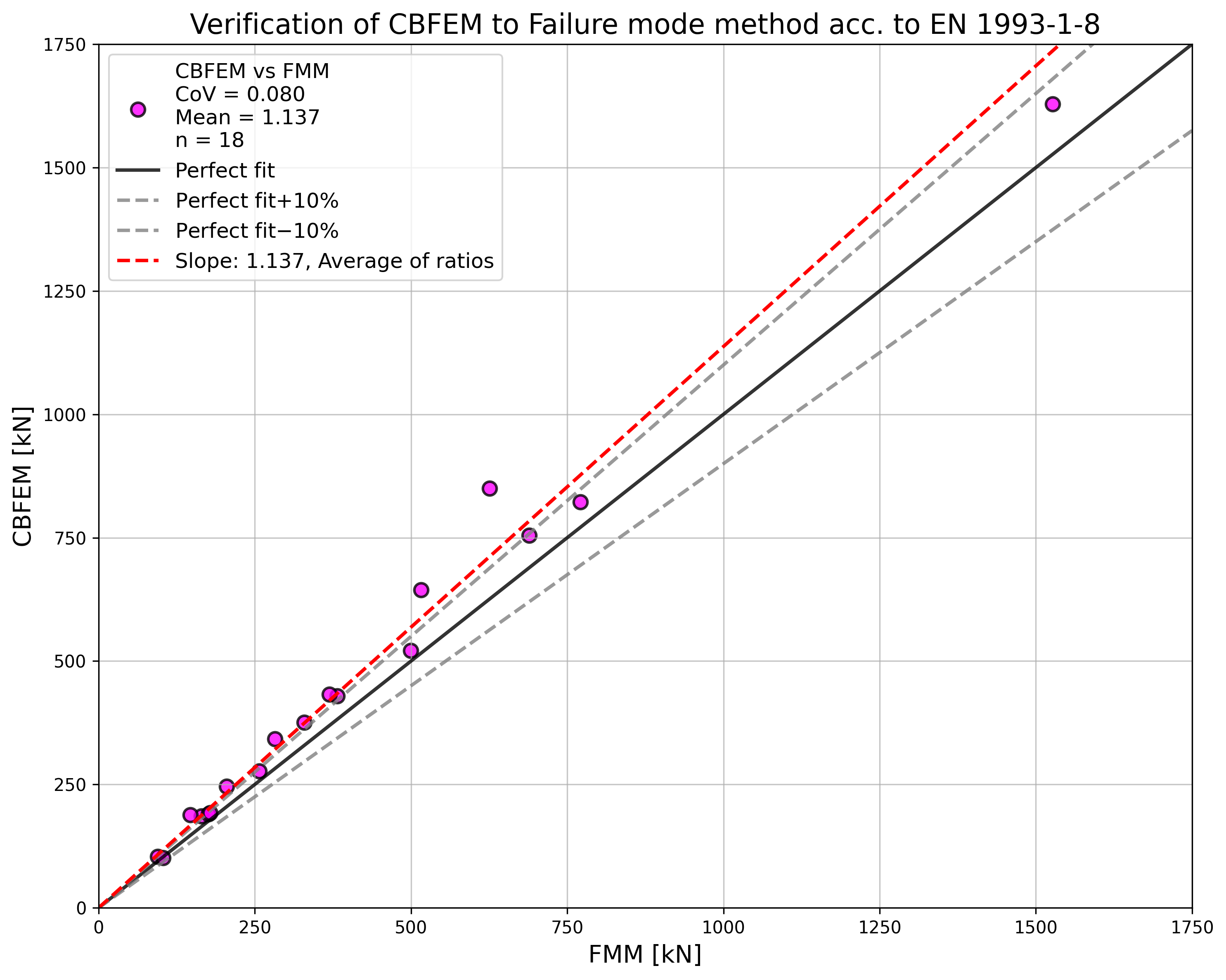
การศึกษาแสดงให้เห็นความสอดคล้องกันที่ดีสำหรับกรณีแรงกระทำที่ใช้ส่วนใหญ่ ผลลัพธ์ถูกสรุปในแผนภาพที่เปรียบเทียบค่าการออกแบบความต้านทานของ CBFEM และ FMM ดู Fig. 7.1.7 ผลลัพธ์แสดงให้เห็นว่าความแตกต่างระหว่างวิธีการคำนวณทั้งสองในกรณีส่วนใหญ่น้อยกว่า 13%
ตัวอย่าง Benchmark
ข้อมูลนำเข้า
Chord
- เหล็ก S355
- หน้าตัด CHS219.1/6,3
Brace
- เหล็ก S355
- หน้าตัด CHS60,3/5,0
- มุมระหว่างชิ้นส่วน brace และ chord 90°
รอยเชื่อม
- รอยเชื่อมชนรอบ brace
การรับแรง
- โดยแรงกระทำต่อ brace ในแรงอัด
ขนาดตาข่าย
- 64 องค์ประกอบตามพื้นผิวของชิ้นส่วนกลวงทรงกระบอก
ผลลัพธ์
- ค่าการออกแบบความต้านทานในแรงอัดคือ NRd = 103.9 kN
- รูปแบบการวิบัติในการออกแบบคือการเกิดพลาสติกของ chord
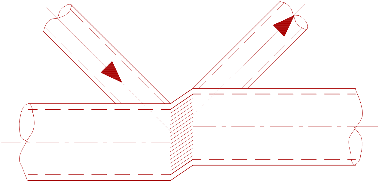
จุดต่อ CHS แบบ K ระนาบเดียว
ภาพรวมของตัวอย่างที่พิจารณาในการศึกษาแสดงไว้ใน Tab. 7.1.7 กรณีที่เลือกครอบคลุมช่วงกว้างของอัตราส่วนทางเรขาคณิตของจุดต่อ รูปทรงเรขาคณิตของจุดต่อพร้อมขนาดแสดงไว้ใน Fig. 7.1.8 ในกรณีที่เลือก จุดต่อวิบัติตามวิธีที่อิงตามรูปแบบการวิบัติ (FMM) โดยการเกิดพลาสติกของ chord หรือแรงเฉือนทะลุ
Tab. 7.1.7 ภาพรวมตัวอย่าง
| ตัวอย่าง | Chord | Brace | ช่องว่าง | มุม | วัสดุ | ||
| หน้าตัด | หน้าตัด | g | fy | fu | E | ||
| [mm] | [°] | [MPa] | [MPa] | [GPa] | |||
| 1 | CHS219,1/8,0 | CHS88,9/5,0 | 23.8 | 60 | 355 | 490 | 210 |
| 2 | CHS219,1/12,5 | CHS88,9/5,0 | 23.8 | 60 | 355 | 490 | 210 |
| 3 | CHS219,1/5,0 | CHS88,9/5,0 | 23.8 | 60 | 355 | 490 | 210 |
| 4 | CHS219,1/10,0 | CHS60,3/5,0 | 56.9 | 60 | 355 | 490 | 210 |
| 5 | CHS219,1/6,3 | CHS88,9/5,0 | 23.8 | 60 | 355 | 490 | 210 |
| 6 | CHS219,1/6,3 | CHS60,3/5,0 | 56.9 | 60 | 355 | 490 | 210 |
| 7 | CHS219,1/8,0 | CHS76,1/5,0 | 38.6 | 60 | 355 | 490 | 210 |
| 8 | CHS219,1/10,0 | CHS76,1/5,0 | 38.6 | 60 | 355 | 490 | 210 |
| 9 | CHS219,1/6.3 | CHS48,3/65,0 | 70.7 | 60 | 355 | 490 | 210 |
| 10 | CHS219,1/12,5 | CHS48,3/5,0 | 70.7 | 60 | 355 | 490 | 210 |
การตรวจสอบความต้านทาน
ผลลัพธ์ของวิธีที่อิงตามรูปแบบการวิบัติ (FMM) ถูกเปรียบเทียบกับผลลัพธ์ของ CBFEM การเปรียบเทียบมุ่งเน้นที่ความต้านทานและรูปแบบการวิบัติในการออกแบบ ผลลัพธ์แสดงไว้ใน Tab. 7.1.8 และใน Fig. 7.1.9
Tab. 7.1.8 การเปรียบเทียบผลลัพธ์ค่าการออกแบบความต้านทานโดย CBFEM และ FMM
การศึกษาแสดงให้เห็นความสอดคล้องกันที่ดีสำหรับกรณีแรงกระทำที่ใช้ ผลลัพธ์ถูกสรุปในแผนภาพที่เปรียบเทียบค่าการออกแบบความต้านทานของ CBFEM และ FMM ดู Fig. 7.1.6 ผลลัพธ์แสดงให้เห็นว่าความแตกต่างระหว่างวิธีการคำนวณทั้งสองในทุกกรณีน้อยกว่า 12 %
ตัวอย่าง Benchmark
ข้อมูลนำเข้า
Chord
- เหล็ก S355
- หน้าตัด CHS 219.1/8.0
Brace
- เหล็ก S355
- หน้าตัด CHS 88.9/5.0
- มุมระหว่างชิ้นส่วน brace และ chord 60°
- ช่องว่างระหว่าง brace g = 23.8 mm
รอยเชื่อม
- รอยเชื่อมชนรอบ brace
การรับแรง
- โดยแรงกระทำต่อ brace ในแรงอัด
ขนาดตาข่าย
- 64 องค์ประกอบตามพื้นผิวของชิ้นส่วนกลวงทรงกระบอก
ผลลัพธ์
- ค่าการออกแบบความต้านทานในแรงอัดคือ NRd = 328.8 kN
- รูปแบบการวิบัติในการออกแบบคือการเกิดพลาสติกของ chord
คำอธิบาย
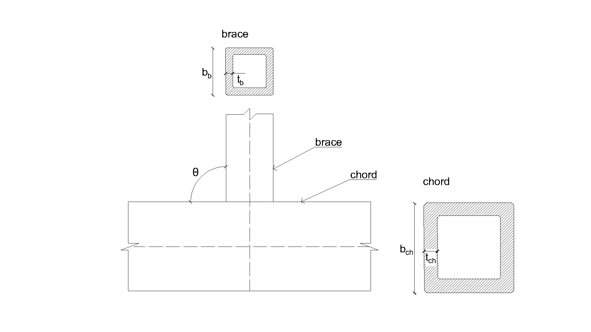
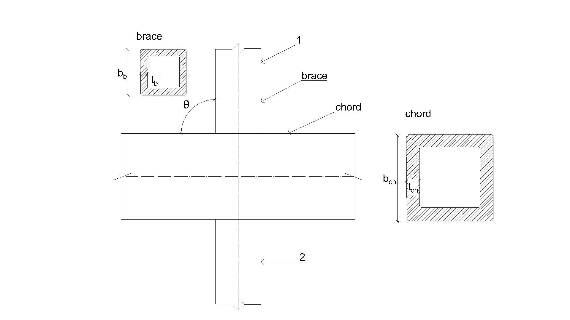
ในบทนี้ จะทำการตรวจสอบจุดต่อแบบ T, X และ K ที่มีช่องว่าง (gap) ของส่วนตัดกลวงสี่เหลี่ยม สี่เหลี่ยมจัตุรัส แบบเชื่อมในระนาบเดียว ที่ทำนายด้วย CBFEM ชิ้นส่วนค้ำยัน (brace) ส่วนตัดกลวงสี่เหลี่ยมจัตุรัส (SHS) ถูกเชื่อมโดยตรงกับคอร์ด RHS โดยไม่ใช้แผ่นเสริม จุดต่อรับแรงในแนวแกน ใน CBFEM ความต้านทานการออกแบบถูกจำกัดด้วยความเครียด 5 % หรือแรงที่สอดคล้องกับการเสียรูปของจุดต่อ 0,03b0 และใน FMM โดยทั่วไปจะจำกัดด้วยการเสียรูปนอกระนาบของแผ่น 0,03b0 โดยที่ b0 คือความลึกของคอร์ด RHS ดู Lu et al. (1994)
วิธีรูปแบบการวิบัติ
ในกรณีของจุดต่อแบบ T, Y, X หรือ K ที่มีช่องว่าง รับแรงในแนวแกน ของส่วนตัดกลวงสี่เหลี่ยมแบบเชื่อม อาจเกิดรูปแบบการวิบัติได้ห้าแบบ ได้แก่ การวิบัติของหน้าคอร์ด การเกิดพลาสติกของคอร์ด การวิบัติของผนังด้านข้างคอร์ด การวิบัติของเอวคอร์ด การวิบัติจากแรงเฉือนของคอร์ด การวิบัติจากแรงเฉือนทะลุ และการวิบัติของชิ้นส่วนค้ำยัน ในการศึกษานี้ การวิบัติของหน้าคอร์ด การวิบัติของชิ้นส่วนค้ำยัน และการวิบัติจากแรงเฉือนทะลุ ถูกตรวจสอบสำหรับจุดต่อแบบ T, Y และ X และการวิบัติของหน้าคอร์ด การวิบัติจากแรงเฉือนของคอร์ด การวิบัติของชิ้นส่วนค้ำยัน และการวิบัติจากแรงเฉือนทะลุ ถูกตรวจสอบสำหรับจุดต่อแบบ K ที่มีช่องว่าง ดูรูปที่ 7.2.1 รอยเชื่อมที่ออกแบบตาม EN 1993-1-8:2005 ไม่ใช่ส่วนประกอบที่อ่อนแอที่สุดในจุดต่อ
การวิบัติของหน้าคอร์ด
ความต้านทานการออกแบบของหน้าคอร์ด RHS ถูกกำหนดโดยแบบจำลอง FMM ในหัวข้อ 9.5 ของ EN 1993‑1-8:2020 วิธีนี้ยังระบุไว้ใน ISO/FDIS 14346 และอธิบายรายละเอียดใน Wardenier et al. (2010) ความต้านทานการออกแบบของจุดต่อแบบ T, Y หรือ X รับแรงในแนวแกน ของส่วนตัดกลวงสี่เหลี่ยมแบบเชื่อม คือ
ความต้านทานการออกแบบของจุดต่อแบบ K ที่มีช่องว่าง รับแรงในแนวแกน ของส่วนตัดกลวงสี่เหลี่ยมแบบเชื่อม คือ
โดยที่ Cf คือปัจจัยวัสดุ fy0 คือความเค้นคราก (yield stress) ของคอร์ด t0 คือความหนาผนังของคอร์ด η คืออัตราส่วนความสูงของชิ้นส่วนค้ำยันต่อความกว้างของคอร์ด β คืออัตราส่วนความกว้างของชิ้นส่วนค้ำยันต่อความกว้างของคอร์ด qi คือมุมระหว่างชิ้นส่วนค้ำยัน i กับคอร์ด (i = 1, 2) Qf คือฟังก์ชันความเค้นของคอร์ด และ γ คืออัตราส่วนความชะลูดของคอร์ด
การวิบัติของชิ้นส่วนค้ำยัน
ความต้านทานการออกแบบของหน้าคอร์ด RHS สามารถกำหนดได้โดยใช้วิธีที่ระบุโดยแบบจำลอง FMM ในหัวข้อ 9.5 ของ EN 1993-1-8:2020 ความต้านทานการออกแบบของจุดต่อแบบ T, Y หรือ X รับแรงในแนวแกน ของส่วนตัดกลวงสี่เหลี่ยมแบบเชื่อม คือ
ความต้านทานการออกแบบของจุดต่อแบบ K ที่มีช่องว่าง รับแรงในแนวแกน ของส่วนตัดกลวงสี่เหลี่ยมแบบเชื่อม คือ
โดยที่ Cf คือปัจจัยวัสดุ fyi คือความเค้นครากของชิ้นส่วนค้ำยัน i (i = 1, 2) ti คือความหนาผนังของชิ้นส่วนค้ำยัน i hi คือความสูงของชิ้นส่วนค้ำยัน i bi คือความกว้างของชิ้นส่วนค้ำยัน i beff คือความกว้างประสิทธิผลของชิ้นส่วนค้ำยัน
แรงเฉือนทะลุ
ความต้านทานการออกแบบของจุดต่อแบบ T, Y หรือ X รับแรงในแนวแกน ของส่วนตัดกลวงสี่เหลี่ยมแบบเชื่อม คือ
ความต้านทานการออกแบบของจุดต่อแบบ K ที่มีช่องว่าง รับแรงในแนวแกน ของส่วนตัดกลวงสี่เหลี่ยมแบบเชื่อม คือ
โดยที่ Cf คือปัจจัยวัสดุ fy0 คือความเค้นครากของคอร์ด t0 คือความหนาผนังของคอร์ด qi คือมุมระหว่างชิ้นส่วนค้ำยัน i กับคอร์ด (i = 1, 2) hi คือความสูงของชิ้นส่วนค้ำยัน i bi คือความกว้างของชิ้นส่วนค้ำยัน i และ be,p คือความกว้างประสิทธิผลสำหรับแรงเฉือนทะลุ
การวิบัติจากแรงเฉือนของคอร์ด
ความต้านทานการออกแบบของจุดต่อแบบ K ที่มีช่องว่าง รับแรงในแนวแกน ของส่วนตัดกลวงสี่เหลี่ยมแบบเชื่อม คือ
โดยที่ fy0 คือความเค้นครากของคอร์ด Av,0,gap คือพื้นที่ประสิทธิผลสำหรับการวิบัติจากแรงเฉือนของคอร์ด และ qi คือมุมระหว่างชิ้นส่วนค้ำยัน i กับคอร์ด (i = 1, 2)
ขอบเขตความถูกต้อง
CBFEM ได้รับการตรวจสอบสำหรับจุดต่อแบบ T, Y, X และ K ที่มีช่องว่างทั่วไป ของส่วนตัดกลวงสี่เหลี่ยมแบบเชื่อม ขอบเขตความถูกต้องสำหรับจุดต่อเหล่านี้ถูกกำหนดไว้ในตารางที่ 9.2 ของ prEN 1993-1-8:2020 ดูตารางที่ 7.2.1 ขอบเขตความถูกต้องเดียวกันนี้ถูกนำไปใช้กับแบบจำลอง CBFEM นอกขอบเขตความถูกต้องของ FMM ควรจัดเตรียมการทดลองเพื่อการตรวจสอบ หรือดำเนินการตรวจสอบตามแบบจำลองการวิจัยที่ผ่านการตรวจสอบแล้ว
Tab. 7.2.1 ขอบเขตความถูกต้องสำหรับวิธีรูปแบบการวิบัติ ตารางที่ 9.2 ของ EN 1993-1-8:2020
| ทั่วไป | |||
| คอร์ด | แรงอัด | Class 1 หรือ 2 และ (แต่สำหรับจุดต่อแบบ X: ) |
| แรงดึง | (แต่สำหรับจุดต่อแบบ X: ) | |
| ชิ้นส่วนค้ำยัน CHS | แรงอัด | Class 1 หรือ 2 และ และ |
| แรงดึง | และ |
7.2.2 จุดต่อ T และ Y-SHS แบบระนาบเดียว
ภาพรวมของตัวอย่างที่พิจารณาแสดงไว้ในตารางที่ 7.2.2 กรณีที่เลือกครอบคลุมอัตราส่วนทางเรขาคณิตของจุดต่อในช่วงกว้าง รูปทรงเรขาคณิตของจุดต่อพร้อมขนาดแสดงในรูปที่ 7.2.2 จุดต่อที่เลือกวิบัติตามวิธีที่อิงกับ FMM ด้วยการวิบัติของหน้าคอร์ดหรือการวิบัติของชิ้นส่วนค้ำยัน
Tab. 7.2.2 ภาพรวมตัวอย่าง
| ตัวอย่าง | คอร์ด | ชิ้นส่วนค้ำยัน | มุม | วัสดุ | ||
| หน้าตัด | หน้าตัด | θ1 | fy | fu | E | |
| [°] | [MPa] | [MPa] | [GPa] | |||
| 1 | SHS200/6.3 | SHS90/8.0 | 90 | 355 | 490 | 210 |
| 2 | SHS200/8.0 | SHS90/8.0 | 90 | 355 | 490 | 210 |
| 3 | SHS200/12.5 | SHS120/12.5 | 90 | 355 | 490 | 210 |
| 4 | SHS200/6.3 | SHS140/12.5 | 60 | 355 | 490 | 210 |
| 5 | SHS200/8.0 | SHS80/8.0 | 60 | 355 | 490 | 210 |
| 6 | SHS200/10.0 | SHS120/12.5 | 60 | 355 | 490 | 210 |
| 7 | SHS200/12.5 | SHS90/8.0 | 60 | 355 | 490 | 210 |
| 8 | SHS200/6.3 | SHS100/10.0 | 30 | 355 | 490 | 210 |
| 9 | SHS200/8.0 | SHS150/16.0 | 30 | 355 | 490 | 210 |
| 10 | SHS200/10.0 | SHS100/10.0 | 30 | 355 | 490 | 210 |
| 11 | SHS200/12.5 | SHS100/10.0 | 30 | 355 | 490 | 210 |
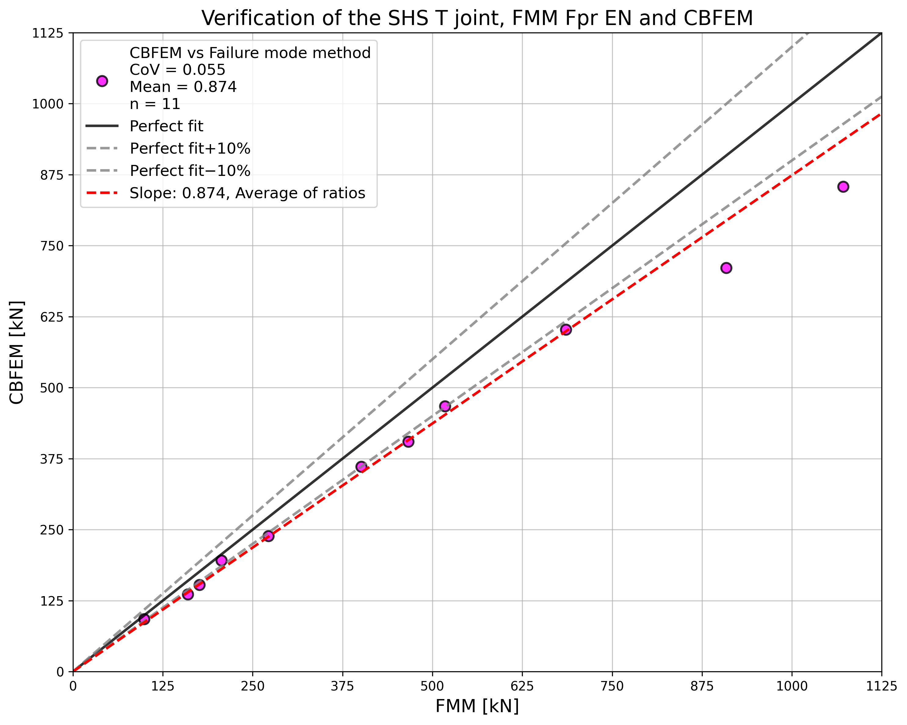
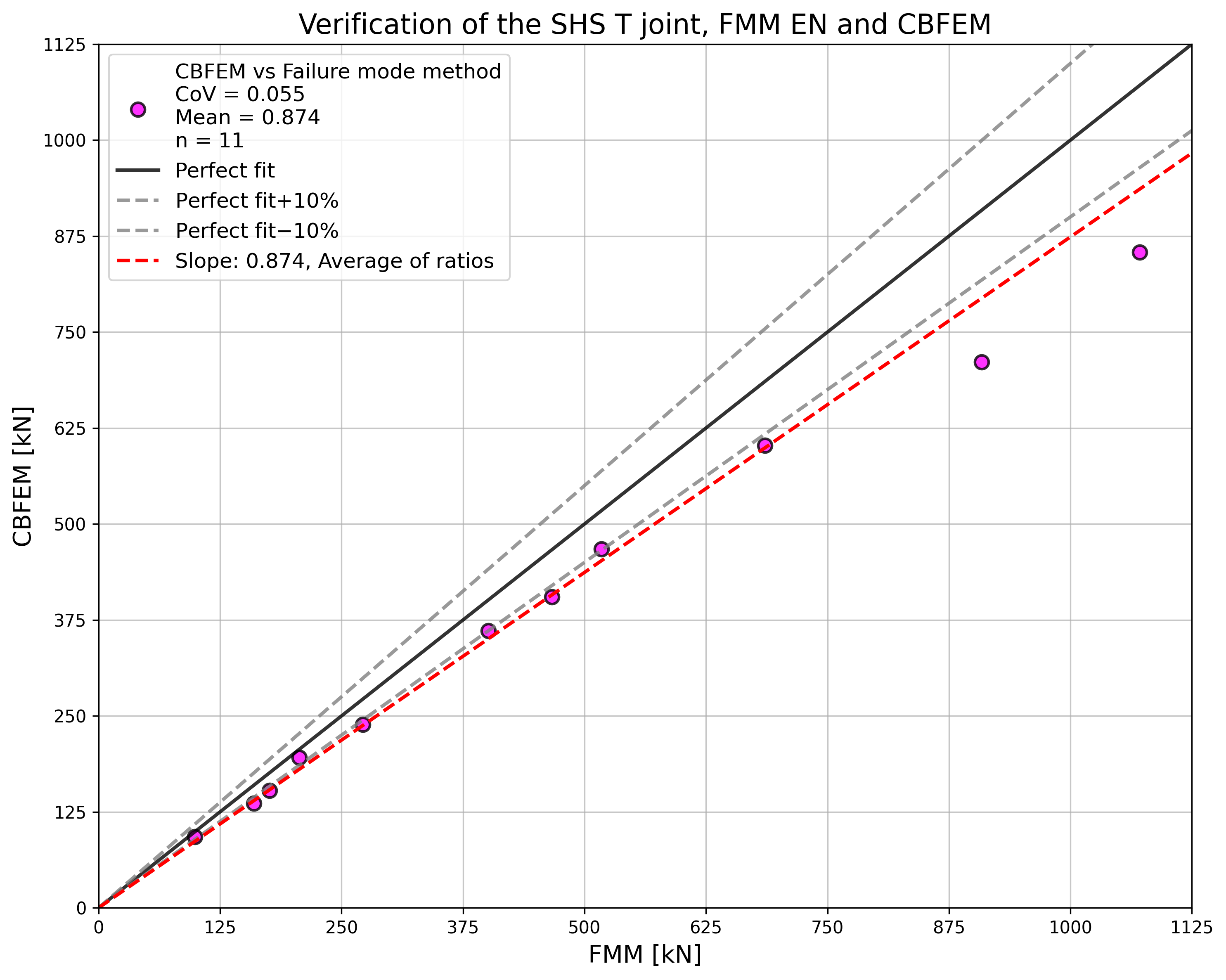
การตรวจสอบความต้านทาน
ผลลัพธ์ของ FMM ถูกเปรียบเทียบกับผลลัพธ์ของ CBFEM การเปรียบเทียบมุ่งเน้นที่ความต้านทานและรูปแบบการวิบัติในการออกแบบ ผลลัพธ์แสดงไว้ในตารางที่ 7.2.3
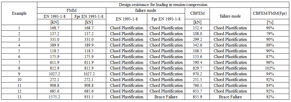
Tab. 7.2.3 การเปรียบเทียบผลลัพธ์ของค่าการออกแบบความต้านทานในแรงดึง/แรงอัด ที่ทำนายโดย CBFEM และ FMM
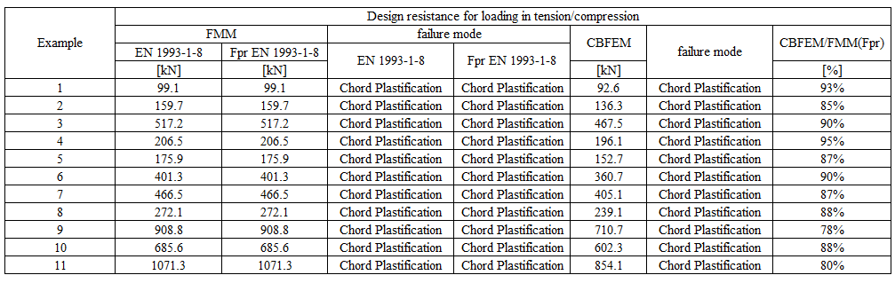
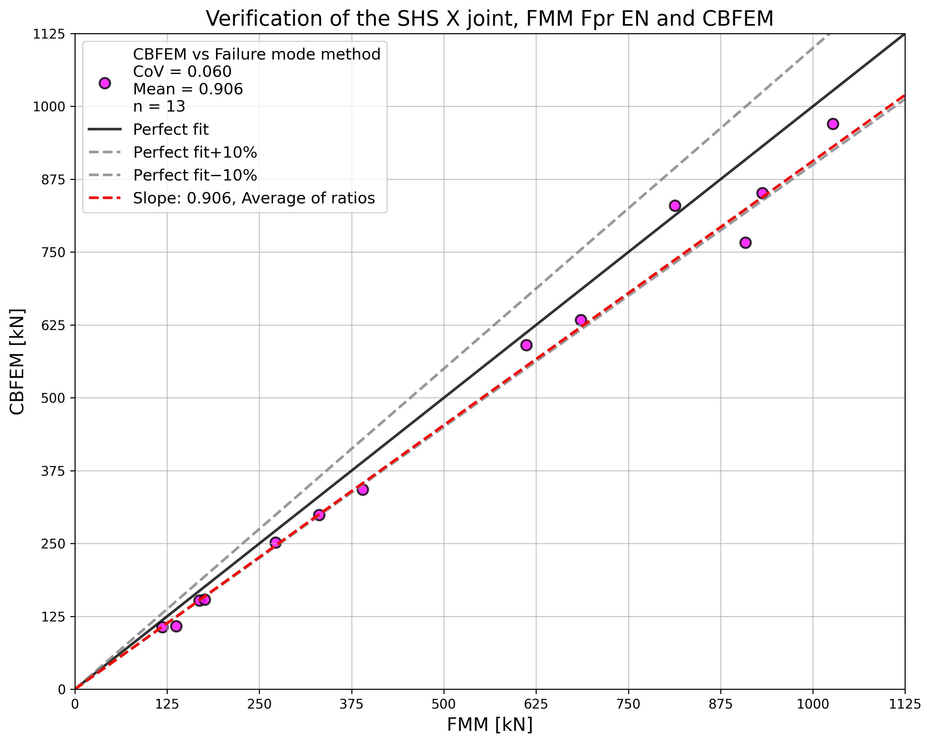
การศึกษาแสดงให้เห็นความสอดคล้องที่ดีสำหรับกรณีแรงกระทำที่ใช้ ผลลัพธ์ถูกสรุปในแผนภาพที่เปรียบเทียบค่าการออกแบบความต้านทานของ CBFEM และ FMM ดูรูปที่ 7.2.3 ผลลัพธ์แสดงให้เห็นว่าความแตกต่างระหว่างวิธีการคำนวณทั้งสองในทุกกรณีน้อยกว่า 10 %
ตัวอย่าง Benchmark
ข้อมูลนำเข้า
คอร์ด
- เหล็ก S355
- หน้าตัด SHS 200×200×6.3
ชิ้นส่วนค้ำยัน
- เหล็ก S355
- หน้าตัด SHS 90×90×8.0
- มุมระหว่างชิ้นส่วนค้ำยันกับคอร์ด 90°
รอยเชื่อม
- รอยเชื่อมชน
ขนาดตาข่าย
- 16 องค์ประกอบบนเอวที่ใหญ่ที่สุดของชิ้นส่วนกลวงสี่เหลี่ยม
การรับแรง
- โดยแรงกระทำต่อชิ้นส่วนค้ำยันในแรงอัด/แรงดึง
ผลลัพธ์
- ความต้านทานการออกแบบในแรงอัด/แรงดึง คือ NRd = 92.6 kN
- รูปแบบการวิบัติในการออกแบบคือการวิบัติของหน้าคอร์ด
จุดต่อ X-SHS แบบระนาบเดียว
ภาพรวมของตัวอย่างที่พิจารณาแสดงไว้ในตารางที่ 7.2.4 กรณีที่เลือกครอบคลุมอัตราส่วนทางเรขาคณิตของจุดต่อในช่วงกว้าง จุดต่อที่เลือกวิบัติตามวิธีที่อิงกับ FMM ด้วยการวิบัติของหน้าคอร์ดหรือการวิบัติของชิ้นส่วนค้ำยัน
Tab. 7.2.4 ภาพรวมตัวอย่าง
| ตัวอย่าง | คอร์ด | ชิ้นส่วนค้ำยัน | มุม | วัสดุ | ||
| หน้าตัด | หน้าตัด | θ | fy | fu | E | |
| [°] | [MPa] | [MPa] | [GPa] | |||
| 1 | SHS200/6.3 | SHS140/12.5 | 90 | 355 | 490 | 210 |
| 2 | SHS200/8.0 | SHS70/8.0 | 90 | 355 | 490 | 210 |
| 3 | SHS200/10.0 | SHS120/12.5 | 90 | 355 | 490 | 210 |
| 4 | SHS200/12.5 | SHS90/8.0 | 90 | 355 | 490 | 210 |
| 5 | SHS200/6.3 | SHS90/8.0 | 60 | 355 | 490 | 210 |
| 6 | SHS200/8.0 | SHS80/8.0 | 60 | 355 | 490 | 210 |
| 7 | SHS200/10.0 | SHS150/6.3 | 60 | 355 | 490 | 210 |
| 8 | SHS200/12.5 | SHS140/12.5 | 60 | 355 | 490 | 210 |
| 9 | SHS200/16.0 | SHS120/12.5 | 60 | 355 | 490 | 210 |
| 10 | SHS200/6.3 | SHS100/8.0 | 30 | 355 | 490 | 210 |
| 11 | SHS200/8.0 | SHS150/16.0 | 30 | 355 | 490 | 210 |
| 12 | SHS200/10.0 | SHS100/10.0 | 30 | 355 | 490 | 210 |
| 13 | SHS200/16.0 | SHS90/8.0 | 30 | 355 | 490 | 210 |
การตรวจสอบความต้านทาน
ผลลัพธ์ของวิธีที่อิงกับรูปแบบการวิบัติ (FMM) ถูกเปรียบเทียบกับผลลัพธ์ของ CBFEM การเปรียบเทียบมุ่งเน้นที่ความต้านทานและรูปแบบการวิบัติในการออกแบบ ดูตารางที่ 7.2.5
Tab. 7.2.5 การเปรียบเทียบผลลัพธ์ของการทำนายความต้านทานโดย CBFEM และ FMM
การศึกษาแสดงให้เห็นความสอดคล้องที่ดีสำหรับกรณีแรงกระทำที่ใช้ ผลลัพธ์ถูกสรุปในแผนภาพที่เปรียบเทียบค่าการออกแบบความต้านทานของ CBFEM และ FMM ดูรูปที่ 7.2.4 ผลลัพธ์แสดงให้เห็นว่าความแตกต่างระหว่างวิธีการคำนวณทั้งสองในทุกกรณีน้อยกว่า 13 %

ตัวอย่าง Benchmark
ข้อมูลนำเข้า
คอร์ด
- เหล็ก S355
- หน้าตัด SHS 200×200×6,3
ชิ้นส่วนค้ำยัน
- เหล็ก S355
- หน้าตัด SHS 140×140×12,5
- มุมระหว่างชิ้นส่วนค้ำยันกับคอร์ด 90°
รอยเชื่อม
- รอยเชื่อมชน
ขนาดตาข่าย
- 16 องค์ประกอบบนเอวที่ใหญ่ที่สุดของชิ้นส่วนกลวงสี่เหลี่ยม
การรับแรง
- โดยแรงกระทำต่อชิ้นส่วนค้ำยันในแรงอัด/แรงดึง
ผลลัพธ์
- ความต้านทานการออกแบบในแรงอัด/แรงดึง คือ NRd = 152.4 kN
- รูปแบบการวิบัติในการออกแบบคือการวิบัติของหน้าคอร์ด
7.2.4 จุดต่อ K-SHS แบบระนาบเดียว
ภาพรวมของตัวอย่างที่พิจารณาแสดงไว้ในตารางที่ 7.2.6 กรณีที่เลือกครอบคลุมอัตราส่วนทางเรขาคณิตของจุดต่อในช่วงกว้าง จุดต่อที่เลือกวิบัติตามวิธีที่อิงกับ FMM ด้วยการวิบัติของหน้าคอร์ดหรือการวิบัติของชิ้นส่วนค้ำยัน
Tab. 7.2.6 ภาพรวมตัวอย่าง
| ตัวอย่าง | คอร์ด | ชิ้นส่วนค้ำยัน | มุม | วัสดุ | ||
| หน้าตัด | หน้าตัด | θ | fy | fu | E | |
| [°] | [MPa] | [MPa] | [GPa] | |||
| 1 | SHS180/10.0 | SHS70/3.0 | 45 | 355 | 490 | 210 |
| 2 | SHS180/10.0 | SHS70/3.6 | 45 | 355 | 490 | 210 |
| 3 | SHS200/8.0 | SHS80/3.6 | 45 | 355 | 490 | 210 |
| 4 | SHS200/8.0 | SHS100/10.0 | 45 | 355 | 490 | 210 |
| 5 | SHS200/200/10.0 | SHS70/3.6 | 45 | 355 | 490 | 210 |
| 6 | SHS200/200/10.0 | SHS100/4.0 | 45 | 355 | 490 | 210 |
| 7 | SHS200/200/12.5 | SHS70/6.3 | 45 | 355 | 490 | 210 |
| 8 | SHS200/200/12.5 | SHS100/8.0 | 45 | 355 | 490 | 210 |
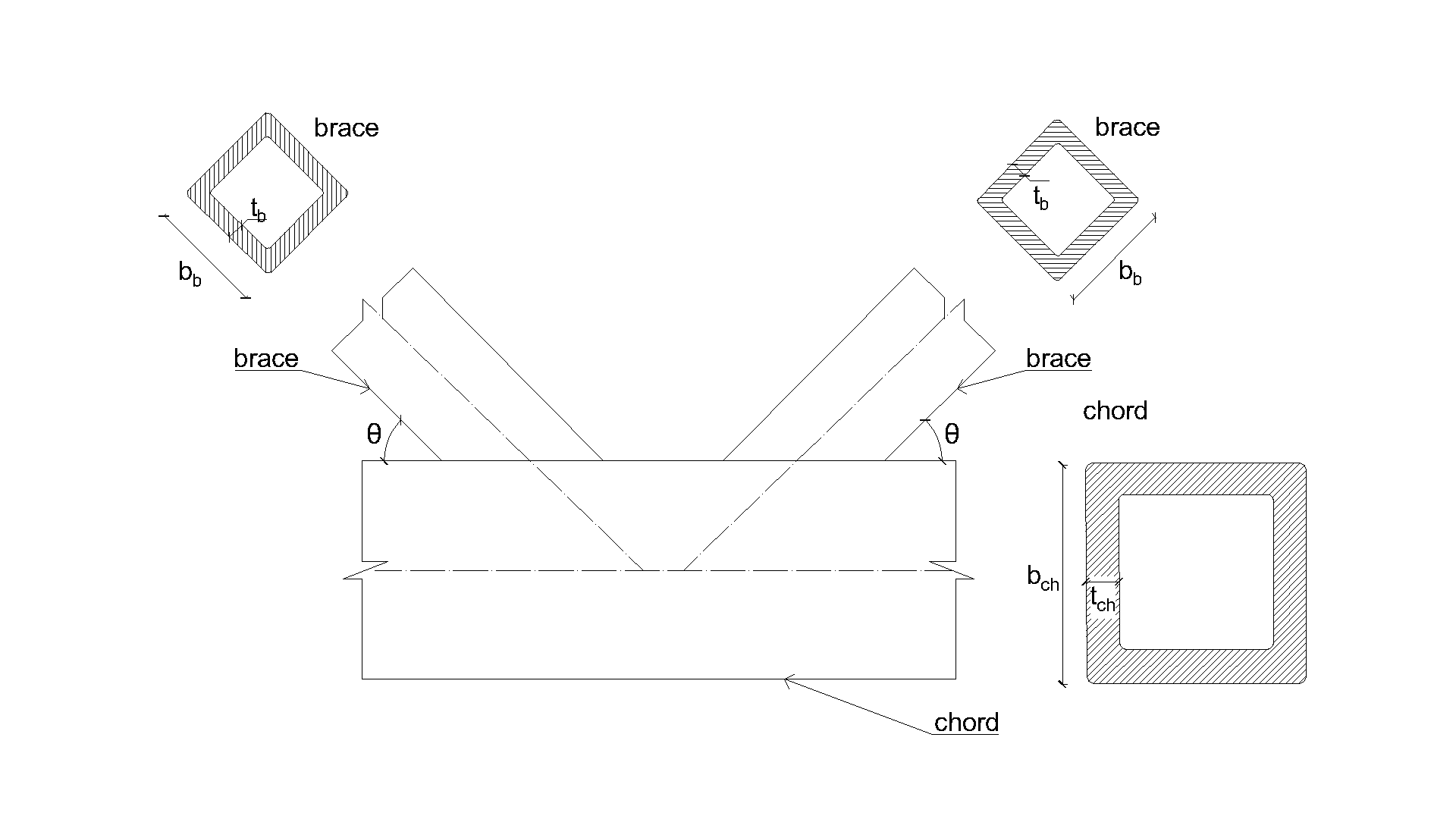
การตรวจสอบ
ผลลัพธ์ของ CBFEM ถูกเปรียบเทียบกับผลลัพธ์ของ FMM การเปรียบเทียบมุ่งเน้นที่ความต้านทานและรูปแบบการวิบัติในการออกแบบ ผลลัพธ์แสดงไว้ในตารางที่ 7.2.7
Tab. 7.2.7 การเปรียบเทียบผลลัพธ์ของการทำนายความต้านทานโดย CBFEM และ FMM
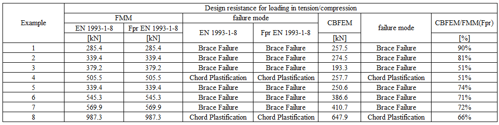
การศึกษาแสดงให้เห็นความสอดคล้องที่ดีสำหรับกรณีแรงกระทำที่ใช้ ผลลัพธ์ถูกสรุปในแผนภาพที่เปรียบเทียบค่าการออกแบบความต้านทานของ CBFEM และ FMM ดูรูปที่ 7.2.5 ผลลัพธ์แสดงให้เห็นว่า CBFEM ให้ผลที่ปลอดภัยกว่าในทุกกรณีเมื่อเปรียบเทียบกับ FMM
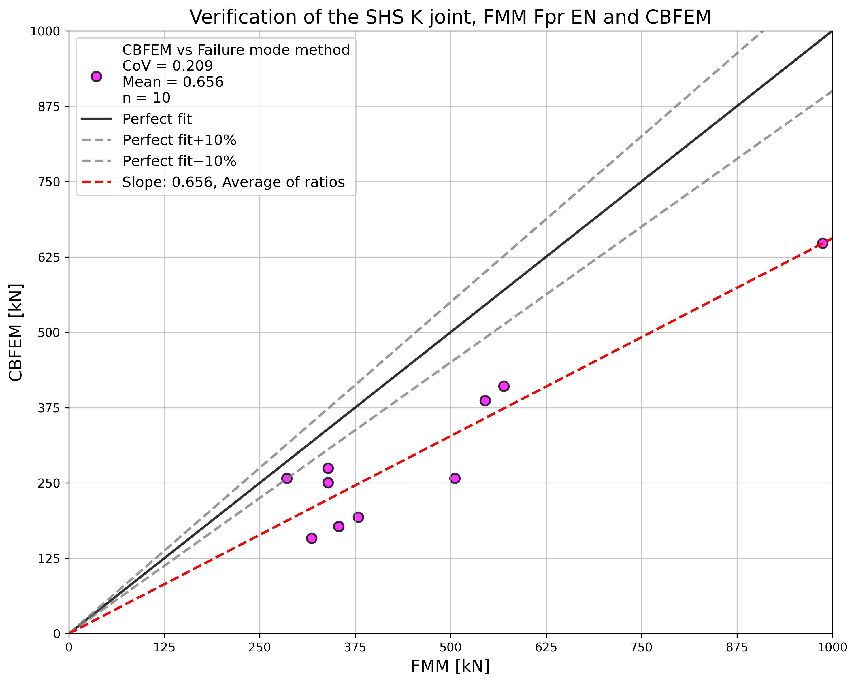
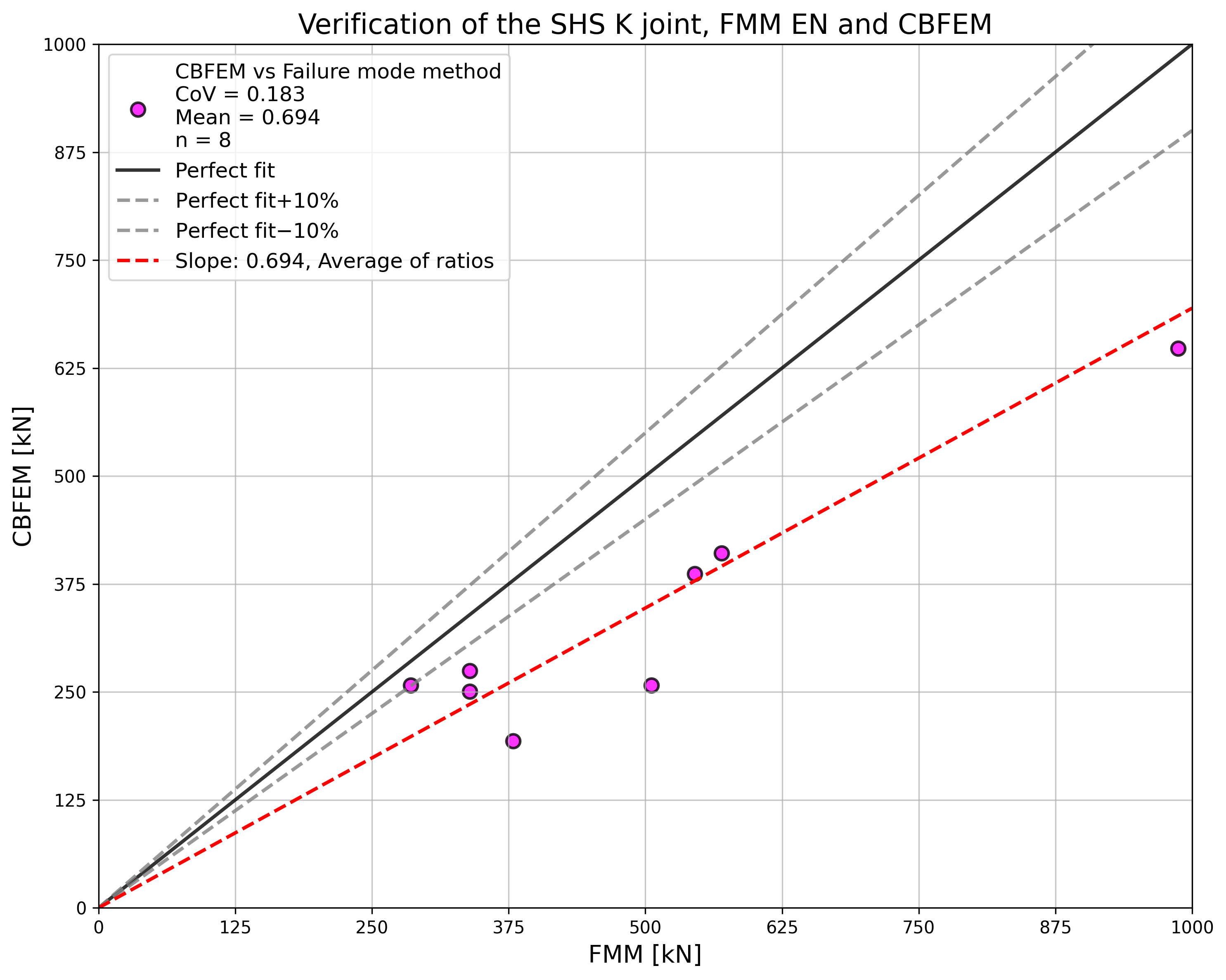
\Fig. 7.2.7 Verification of resistance determined by CBFEM to FMM for the uniplanar SHS K-joint}}}
ตัวอย่าง Benchmark
ข้อมูลนำเข้า
คอร์ด
- เหล็ก S355
- หน้าตัด SHS 180×180×10,0
ชิ้นส่วนค้ำยัน
- เหล็ก S355
- หน้าตัด SHS 70×70×3,0
- มุมระหว่างชิ้นส่วนค้ำยันกับคอร์ด 45°
รอยเชื่อม
- รอยเชื่อมชน
ขนาดตาข่าย
- 16 องค์ประกอบบนเอวที่ใหญ่ที่สุดของชิ้นส่วนกลวงสี่เหลี่ยม
การรับแรง
- โดยแรงกระทำต่อชิ้นส่วนค้ำยันในแรงอัด/แรงดึง
ผลลัพธ์
- ความต้านทานการออกแบบในแรงอัด/แรงดึง คือ NRd = 257.5 kN
- รูปแบบการวิบัติในการออกแบบคือการวิบัติของหน้าคอร์ด
วิธีรูปแบบการวิบัติ
จุดต่อแบบ T ของแผ่นเชื่อมกับท่อกลมกลวงแบบระนาบเดียวที่ทำนายโดย CBFEM ได้รับการตรวจสอบเทียบกับ FMM ในบทนี้ ใน CBFEM ความต้านทานการออกแบบถูกจำกัดโดยการถึง 5 % ของความเครียด หรือแรงที่สอดคล้องกับการเสียรูปของจุดต่อ 3 % d0 โดยที่ d0 คือเส้นผ่านศูนย์กลางของคอร์ด FMM อ้างอิงจากขีดจำกัดแรงสูงสุดหรือขีดจำกัดการเสียรูป 3 % d0 ดู Lu et al. (1994) รอยเชื่อมที่ออกแบบตาม EN 1993‑1‑8:2006 ไม่ใช่ส่วนประกอบที่อ่อนแอที่สุดในจุดต่อ
การครากของหน้าคอร์ด
ความต้านทานการออกแบบของหน้าคอร์ด CHS ถูกกำหนดโดยใช้วิธีที่ระบุในแบบจำลอง FMM ใน Ch. 9 ของ prEN 1993-1-8:2020 และใน ISO/FDIS 14346 ดู Fig. 7.3.1 ความต้านทานการออกแบบของจุดต่อแผ่นเชื่อมกับ CHS ที่รับแรงตามแนวแกนคือ:
จุดต่อแบบ T
แนวขวาง
แนวยาว
จุดต่อแบบ X
แนวขวาง
แนวยาว
โดยที่:
- fy,i – กำลังครากของชิ้นส่วน i (i = 0,1,2 หรือ 3)
- ti – ความหนาของผนังชิ้นส่วน CHS i (i = 0,1,2 หรือ 3)
- – อัตราส่วนของเส้นผ่านศูนย์กลางหรือความกว้างเฉลี่ยของชิ้นส่วนค้ำยันต่อคอร์ด
- – อัตราส่วนของความลึกของชิ้นส่วนค้ำยันต่อเส้นผ่านศูนย์กลางหรือความกว้างของคอร์ด
- – อัตราส่วนของความกว้างหรือเส้นผ่านศูนย์กลางของคอร์ดต่อสองเท่าของความหนาผนัง
- Qf – ตัวประกอบความเค้นในคอร์ด
- Cf – ตัวประกอบวัสดุ
- – ตัวประกอบบางส่วนสำหรับความต้านทานของจุดต่อในโครงถักท่อกลวง
- Ni,Rd – ความต้านทานการออกแบบของจุดต่อที่แสดงในรูปของแรงตามแนวแกนภายในของชิ้นส่วน i (i = 0,1,2 หรือ 3)
ขอบเขตความถูกต้อง
CBFEM ได้รับการตรวจสอบสำหรับจุดต่อทั่วไปของท่อกลมกลวงแบบเชื่อม ขอบเขตความถูกต้องสำหรับจุดต่อเหล่านี้ถูกกำหนดไว้ใน Table 7.8 ของ prEN 1993-1-8:2020 ดู Tab 7.3.1 ขอบเขตความถูกต้องเดียวกันนี้ถูกนำไปใช้กับแบบจำลอง CBFEM นอกขอบเขตความถูกต้องของ FMM ควรจัดเตรียมการทดสอบเชิงทดลองเพื่อการตรวจสอบ หรือดำเนินการตรวจสอบตามแบบจำลองงานวิจัยที่ผ่านการตรวจสอบแล้ว
Tab. 7.3.1 ขอบเขตความถูกต้องสำหรับวิธีรูปแบบการวิบัติ
| ทั่วไป | |||
| คอร์ด | แรงอัด | Class 1 หรือ 2 และ (แต่สำหรับจุดต่อแบบ X: ) |
| แรงดึง | (แต่สำหรับจุดต่อแบบ X: ) | |
| แผ่นแนวขวาง | ||
| แผ่นแนวยาว |
การตรวจสอบความถูกต้อง
ในบทนี้ CBFEM ได้รับการตรวจสอบความถูกต้องเทียบกับแบบจำลอง FMM ของจุดต่อแบบ T ของแผ่นกับ CHS ที่อธิบายไว้ใน prEN 1993-1-8:2020 แบบจำลองถูกเปรียบเทียบกับข้อมูลจากการทดสอบเชิงกลใน Tabs 7.3.2–7.3.3 โดยใช้ความต้านทานที่อ้างอิงจากขีดจำกัดการเสียรูป คุณสมบัติวัสดุและเรขาคณิตของการทดสอบเชิงตัวเลขอธิบายไว้ใน (Voth A.P. and Packer A.J., 2010) การทดสอบที่อยู่นอกขอบเขตความถูกต้องถูกทำเครื่องหมายในตารางด้วยเครื่องหมายดอกจัน * และแสดงในกราฟเพื่อแสดงคุณภาพของเงื่อนไขขอบเขต
Tab. 7.3.2 คุณสมบัติเรขาคณิต คุณสมบัติวัสดุ และความต้านทานของการเชื่อมต่อจากการทดสอบและแบบจำลอง FMM สำหรับจุดต่อแบบ T แนวขวาง
| ID | อ้างอิง | d0 [mm] | t0 [mm] | h1 [mm] | h1/d0 [-] | d0/t0 [-] | fy0 [MPa] |
| TPT 1 | Washio et al. (1970) | 165,2 | 5,2 | 115,6 | 0,7 | 31,8 | 308,0 |
| TPT 2 | Washio et al. (1970) | 165,2 | 5,2 | 148,7 | 0,9 | 31,8 | 308,0 |
| TPT 3 | Washio et al. (1970) | 139,8 | 3,5 | 125,8 | 0,9 | 39,9 | 343,0 |
| TPT 4 | Voth et al. (2012) | 219,2 | 4,5 | 100,3 | 0,5 | 48,8 | 388,8 |
| ID | Nu,exp [kN] | ประเภทกิ่ง | Nu,exp/(t02·fy0) | N1,prEN/(t02·fy0) | Nu,exp/N1,prEN |
| TPT 1 | 169,4 | แรงอัด | 20,34 | 16,25 | 1,25 |
| TPT 2 | 250,5 | แรงอัด | 30,08 | 22,58 | 1,33 |
| TPT 3 | 184,8 | แรงอัด | 43,98 | 24,45 | 1,80 |
| TPT 4 | 282,5 | แรงดึง | 36,04 | 12,45 | 2,89 |
Tab. 7.3.3 คุณสมบัติเรขาคณิต คุณสมบัติวัสดุ และความต้านทานของการเชื่อมต่อจากการทดสอบและแบบจำลอง FMM สำหรับจุดต่อแบบ T แนวยาว
| ID | อ้างอิง | d0 [mm] | t0 [mm] | h1 [mm] | h1/d0 [-] | d0/t0 [-] | fy0 [MPa] |
| TPL 1 | Washio et al. (1970) | 165,2 | 5,2 | 165,2 | 1,0 | 31,8 | 308,0 |
| TPL 2 | Washio et al. (1970) | 165,2 | 5,2 | 330,4 | 2,0 | 31,8 | 308,0 |
| *TPL 3 | Voth et al. (2012) | 219,2 | 4,5 | 99,9 | 0,5 | 48,8 | 388,8 |
| ID | Nu,exp [kN] | ประเภทกิ่ง | Nu,exp/(t02·fy0) | N1,prEN/(t02·fy0) | Nu,exp/N1,prEN |
| TPL 1 | 107,6 | แรงอัด | 12,92 | 10,36 | 1,25 |
| TPL 2 | 127,4 | แรงอัด | 15,30 | 13,32 | 1,15 |
| *TPL 3 | 160,6 | แรงดึง | 20,49 | 8,75 | 2,34 |
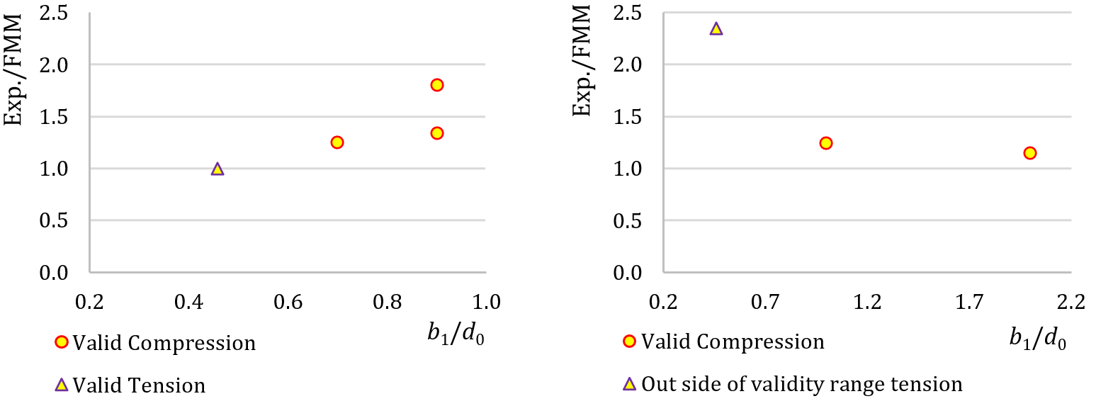
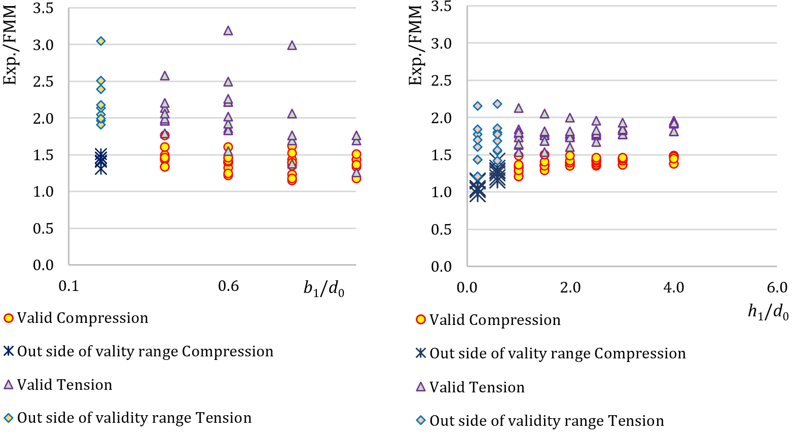
การตรวจสอบความถูกต้องที่แสดงใน Figs 7.3.2 และ 7.3.3 แสดงให้เห็นว่าความแตกต่างจากการทดสอบอยู่ที่อย่างน้อย 15 % โดยทั่วไปอยู่ในด้านที่ปลอดภัย การทดสอบที่อยู่นอกขอบเขตความถูกต้องถูกรวมไว้และทำเครื่องหมายแล้ว ผลลัพธ์แสดงให้เห็นถึงคุณภาพที่ดีของเงื่อนไขขอบเขตที่เลือก
จุดต่อแบบ T ของแผ่นระนาบเดียว
ภาพรวมของตัวอย่างที่พิจารณาในการศึกษาแสดงไว้ใน Tab. 7.3.4 กรณีที่เลือกครอบคลุมอัตราส่วนเรขาคณิตของจุดต่อในช่วงกว้าง เรขาคณิตของจุดต่อพร้อมขนาดแสดงไว้ใน Fig. 7.3.4 ความหนาของแผ่นเท่ากับ 15 mm ในทุกกรณีที่ครอบคลุมในการศึกษานี้
Tab. 7.3.4 ภาพรวมตัวอย่าง
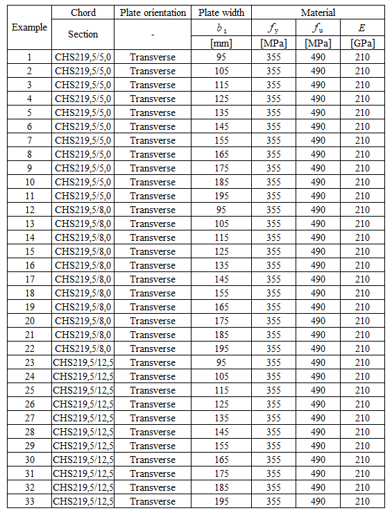
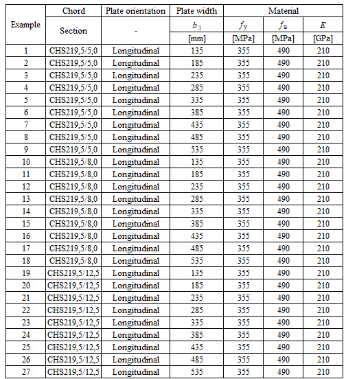
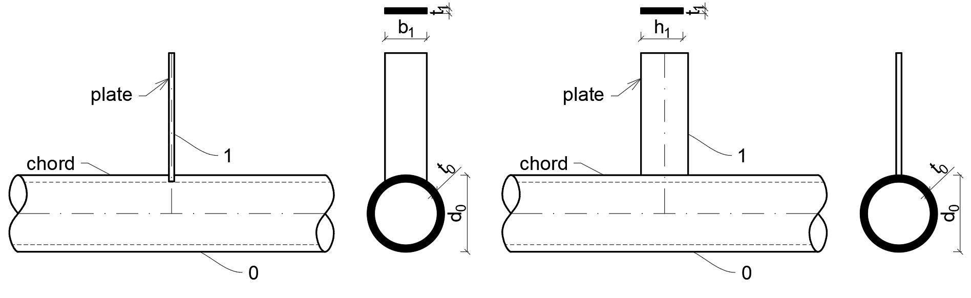
การตรวจสอบ
ผลลัพธ์ของความต้านทานและรูปแบบการวิบัติการออกแบบของ FMM ถูกเปรียบเทียบกับผลลัพธ์ของ CBFEM ใน Tab. 7.3.5 และใน Fig. 7.3.5
Tab. 7.3.5 การตรวจสอบการทำนายความต้านทานโดย CBFEM บน FMM a) แนวขวาง b) แนวยาว
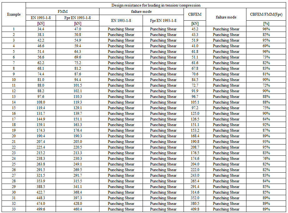
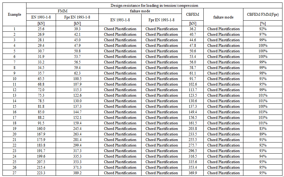
การศึกษาแสดงให้เห็นความสอดคล้องที่ดีสำหรับกรณีแรงกระทำที่ใช้ ผลลัพธ์ถูกสรุปในแผนภาพที่เปรียบเทียบความต้านทานการออกแบบของ CBFEM และ FMM ดู Fig. 7.3.5 ผลลัพธ์แสดงให้เห็นว่าความแตกต่างระหว่างวิธีการคำนวณทั้งสองในทุกกรณีน้อยกว่า 7 %
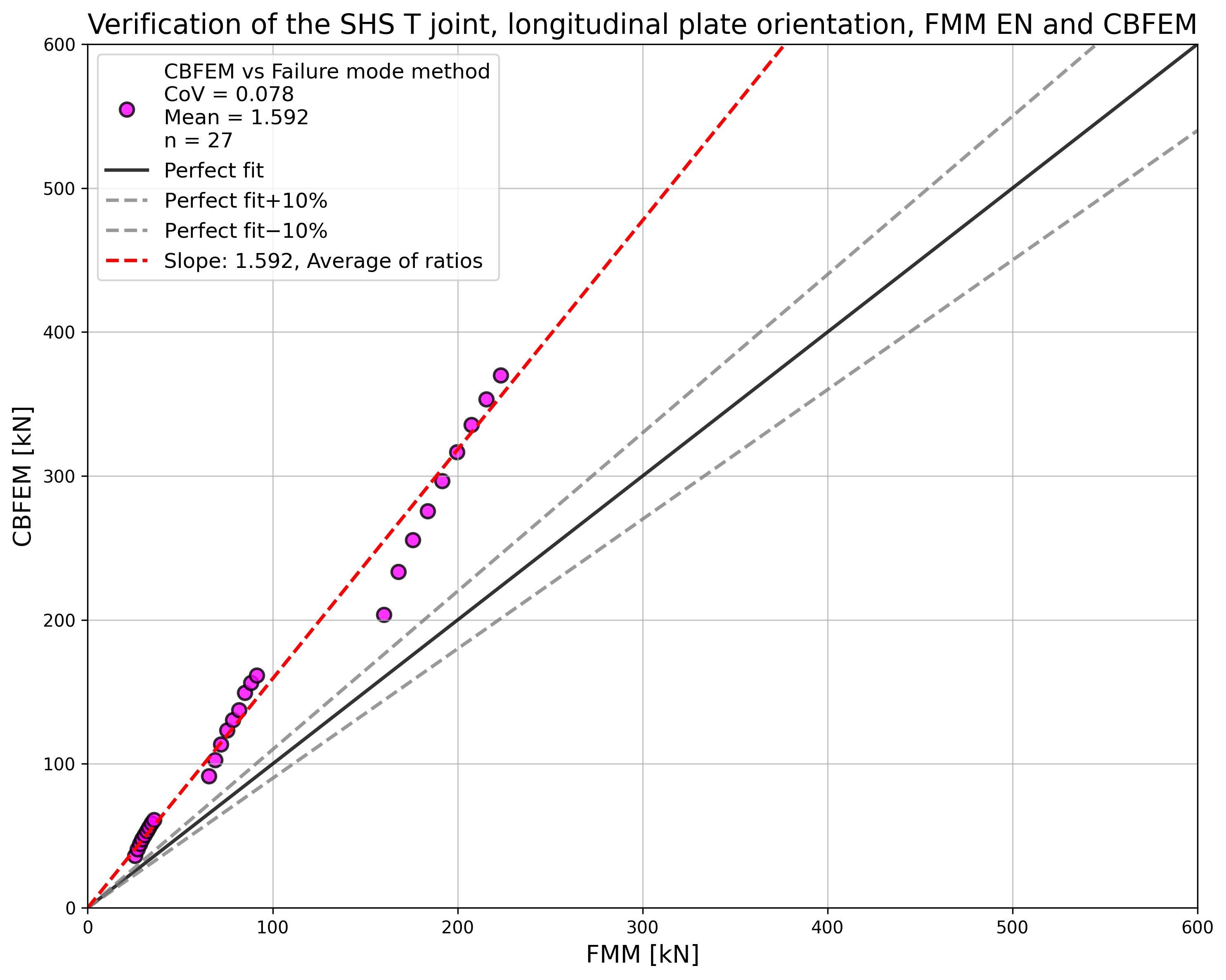
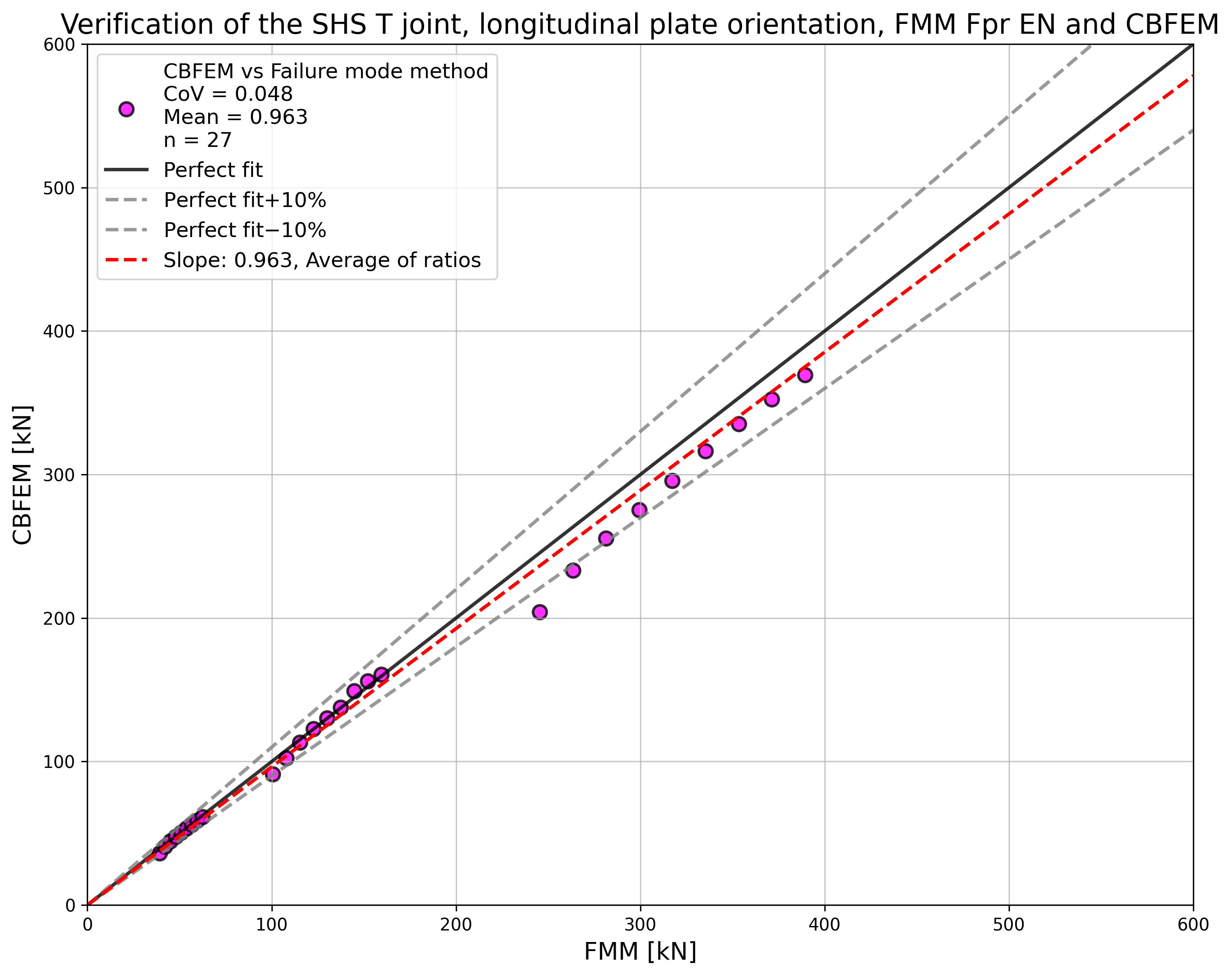
ตัวอย่าง Benchmark
ข้อมูลนำเข้า
คอร์ด
- เหล็ก S355
- หน้าตัด CHS219.1/5,0
กิ่ง
- เหล็ก S355
- แผ่น 95/15 mm
- มุมระหว่างชิ้นส่วนกิ่งและคอร์ด 90° (แนวขวาง)
รอยเชื่อม
- รอยเชื่อมชนรอบกิ่ง
การรับแรง
- โดยแรงกระทำที่กิ่งในแรงอัด
ขนาดตาข่าย
- 64 ช่องตามแนวผิวของชิ้นส่วนท่อกลมกลวง
ผลลัพธ์
- ความต้านทานการออกแบบในแรงอัดคือ NRd = 45,2 kN
- รูปแบบการวิบัติการออกแบบคือการเจาะทะลุแบบแรงเฉือน
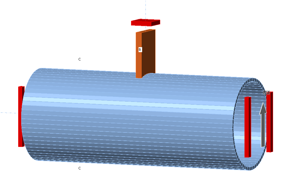
คำอธิบาย
ศึกษาการเชื่อมต่อแบบ T ระนาบเดียวของค้ำยันหน้าตัดกลวงสี่เหลี่ยมผืนผ้ากับคอร์ดหน้าตัดเปิด ซึ่งอยู่ในโครงถักแบบตาข่าย ค้ำยัน RHS ถูกเชื่อมโดยตรงกับคอร์ด H หรือ I ซึ่งเป็นหน้าตัดเปิด โดยไม่ใช้แผ่นเสริมความแข็ง การทำนายด้วยวิธี Component-Based Finite Element (CBFEM) ได้รับการตรวจสอบความถูกต้องกับวิธีรูปแบบการวิบัติ (FM) ที่ใช้งานใน EN 1993-1-8:2005
แบบจำลองเชิงวิเคราะห์
รูปแบบการวิบัติสามแบบเกิดขึ้นในการเชื่อมต่อแบบ T ระนาบเดียวของหน้าตัดกลวงสี่เหลี่ยมผืนผ้าที่เชื่อมกับหน้าตัดเปิด ได้แก่ การครากเฉพาะที่ของค้ำยัน เรียกว่าการวิบัติของค้ำยัน การวิบัติของเอวคอร์ด และการเฉือนของคอร์ด รูปแบบการวิบัติทั้งหมดนี้ได้รับการตรวจสอบในการศึกษานี้ ดูรูปที่ 7.4.1 รอยเชื่อมได้รับการออกแบบให้ไม่เป็นองค์ประกอบที่อ่อนแอที่สุดในจุดต่อตาม EN 1993-1-8:2005 ชิ้นส่วนของโครงถักแบบตาข่ายรับแรงปกติและโมเมนต์ดัด จุดกระทำของแรงภายในของการเชื่อมต่อแบบ T อธิบายได้ดังนี้:
คอร์ด H/I รับแรงตามแนวแกน
แรงปกติในคอร์ดทางขวาและซ้ายของการเชื่อมต่อแบบ T กระทำในทิศทางของแกนตามยาวของคอร์ด
คอร์ด H/I รับแรงเนื่องจากการเบี่ยงเบน
โมเมนต์ดัดทางขวาและซ้ายของการเชื่อมต่อแบบ T ในระนาบของการเชื่อมต่อแบบ T ถูกพิจารณาในคอร์ด และโมเมนต์ดัดเหล่านี้หมุนรอบแกนหนึ่งในระนาบของหน้าตัดคอร์ดสำหรับการหมุนในระนาบของการเชื่อมต่อแบบ T
ค้ำยัน RHS รับแรงตามแนวแกน
แรงปกติในค้ำยันของการเชื่อมต่อแบบ T กระทำในทิศทางของแกนตามยาวของค้ำยัน
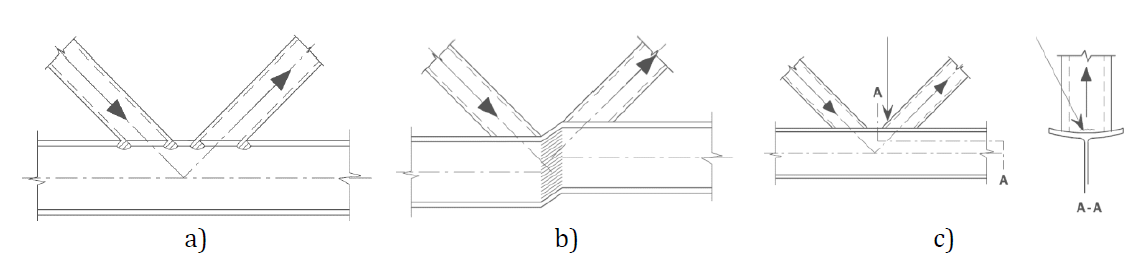
ความต้านทานของเอวคอร์ดถูกกำหนดโดยใช้วิธีที่ระบุในหัวข้อ 7.6 ของ EN 1993-1-8:2005 ซึ่งอธิบายไว้ใน (Wardenier et al., 2010) ความเค้นจากค้ำยันถูกถ่ายผ่านปีกของคอร์ดไปยังพื้นที่ประสิทธิผลของเอวคอร์ด พื้นที่นี้อยู่ในเอวคอร์ดที่จุดซึ่งผนังค้ำยันตัดกับเอวคอร์ด ค่าการออกแบบความต้านทานแรงตามแนวแกนของจุดต่อคือค่าต่ำสุดของค่าการออกแบบความต้านทาน:
การวิบัติของเอวคอร์ด
การเฉือนของคอร์ด
การวิบัติของค้ำยัน
โดยที่
และ คือพื้นที่แรงเฉือนประสิทธิผล
ค่าการออกแบบความต้านทานโมเมนต์ดัดของจุดต่อคือค่าต่ำสุดของค่าการออกแบบความต้านทาน:
การวิบัติของเอวคอร์ด
การวิบัติของค้ำยัน
โดยที่
ภาพรวมของตัวอย่างที่พิจารณาซึ่งรับแรงตามแนวแกนอธิบายไว้ในตารางที่ 7.4.1 ภาพรวมของตัวอย่างที่พิจารณาซึ่งรับโมเมนต์ดัดอธิบายไว้ในตารางที่ 7.4.2 รูปทรงเรขาคณิตของจุดต่อพร้อมขนาดแสดงในรูปที่ 7.4.2
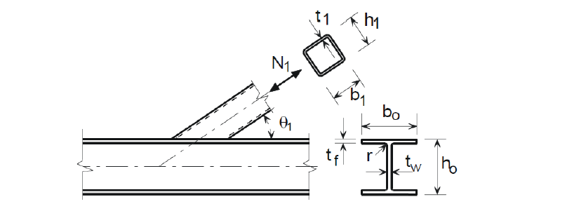
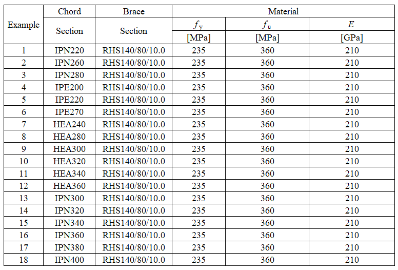
ตารางที่ 7.4.1 ตัวอย่างจุดต่อที่รับแรงตามแนวแกน
ตารางที่ 7.4.2 ตัวอย่างจุดต่อที่รับโมเมนต์ในระนาบ
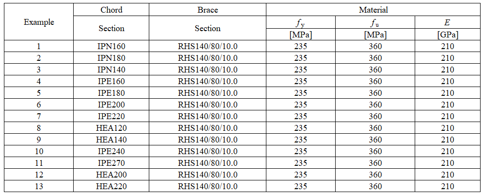
การตรวจสอบความต้านทาน
การศึกษามุ่งเน้นไปที่การเปรียบเทียบรูปแบบการวิบัติและการทำนายค่าการออกแบบความต้านทาน ผลลัพธ์แสดงในตารางที่ 7.4.3 และ 7.4.4
ตารางที่ 7.4.3 การเปรียบเทียบ CBFEM และ FM สำหรับแรงตามแนวแกนในค้ำยัน
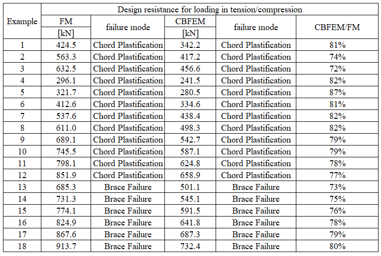
ตารางที่ 7.4.4 การเปรียบเทียบ CBFEM และ FM สำหรับโมเมนต์ในระนาบในค้ำยัน
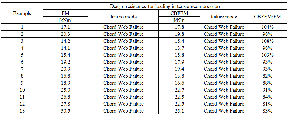
การศึกษาความไวแสดงให้เห็นความสอดคล้องที่ดีสำหรับกรณีแรงกระทำทั้งหมดที่ใช้ ในวิธี CBFEM การปัดเศษของผนังหน้าตัดเปิดถูกทำให้เรียบง่าย ซึ่งให้การประมาณค่าความเค้นในแนวทแยงที่เชื่อมต่อแบบอนุรักษ์นิยม และสมมติฐานของความสามารถรับแรงถึง 15% เพื่อแสดงให้เห็นความแม่นยำของแบบจำลอง CBFEM ผลลัพธ์ของการศึกษาพารามิเตอร์ถูกสรุปในแผนภาพที่เปรียบเทียบค่าการออกแบบความต้านทานโดย CBFEM และ FM ดูรูปที่ 7.4.3
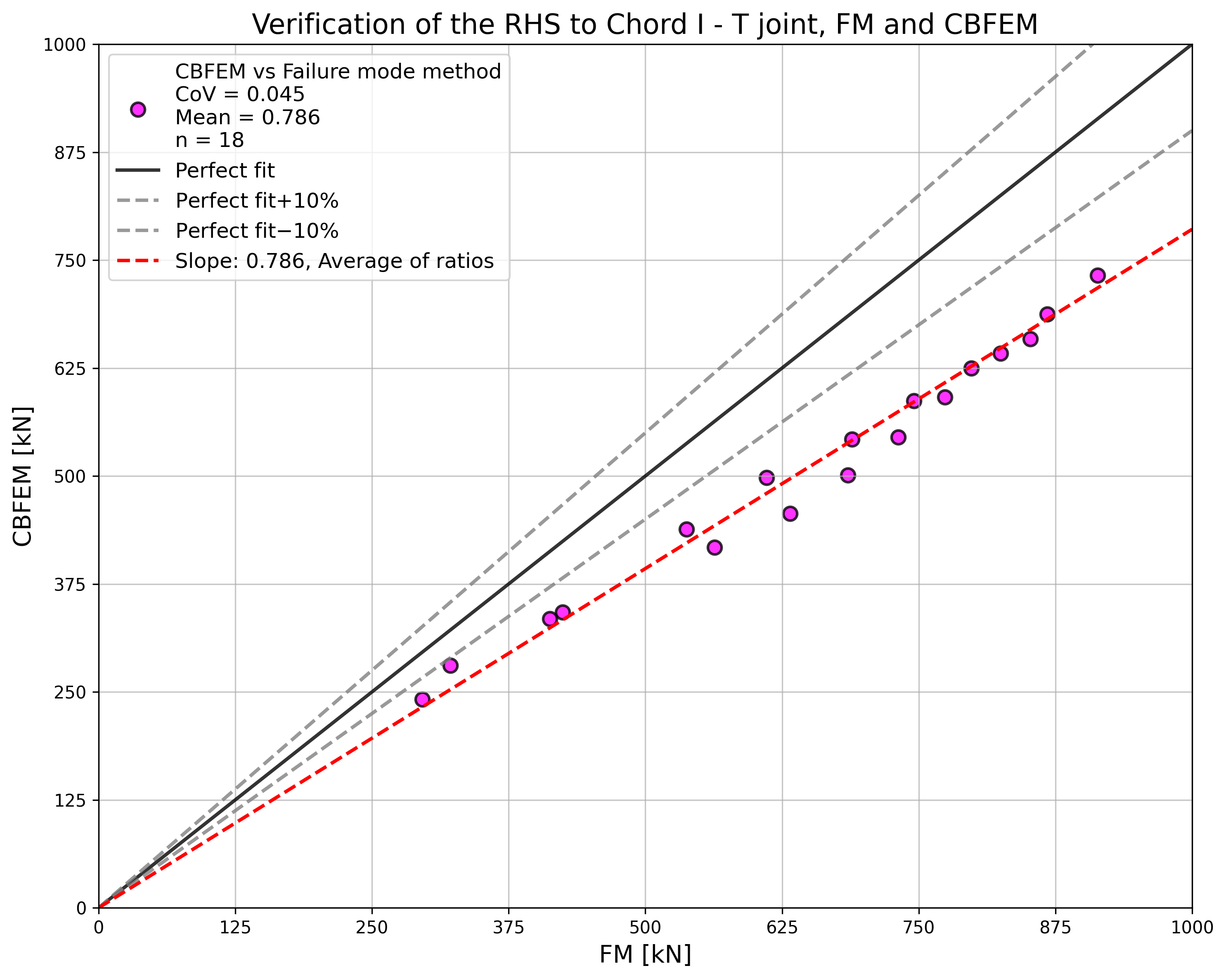
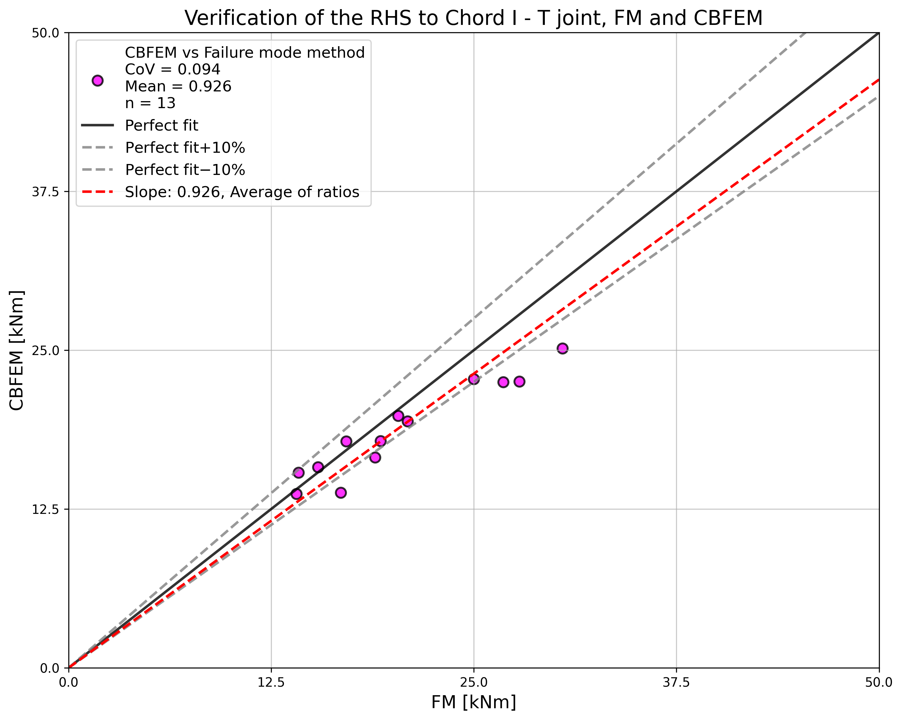
ขอบเขตความถูกต้อง
ขอบเขตความถูกต้องที่ CBFEM ได้รับการตรวจสอบสำหรับการเชื่อมต่อแบบ T ระหว่างหน้าตัดกลวงสี่เหลี่ยมผืนผ้าและหน้าตัดเปิด ถูกกำหนดไว้ในตารางที่ 7.20 ของ EN 1993-1-8:2005 ดูตารางที่ 7.4.5 ในกรณีที่ใช้แบบจำลอง CBFEM นอกขอบเขตความถูกต้องของ FM ควรจัดเตรียมการตรวจสอบกับการทดลองหรือการตรวจสอบกับแบบจำลองการวิจัยที่ผ่านการตรวจสอบแล้ว เพื่อยืนยันคุณภาพของการทำนาย
ตารางที่ 7.4.5 ขอบเขตความถูกต้องของการเชื่อมต่อแบบ T
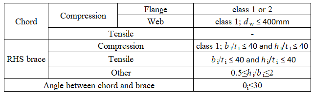
ตัวอย่าง Benchmark
ข้อมูลนำเข้า
คอร์ด
• เหล็ก S235
• IPN280
ค้ำยัน
• เหล็ก S235
• RHS 140×80×10
ขนาดตาข่าย
• 16 องค์ประกอบบนเอวที่ใหญ่ที่สุดของชิ้นส่วนกลวงสี่เหลี่ยมผืนผ้า
ผลลัพธ์
• ค่าการออกแบบความต้านทานในการรับแรงอัด/แรงดึง Fc,Rd = 457 kN (ควรสังเกตว่าความต้านทานถูกคำนวณโดยใช้ฟังก์ชัน "Stop at limit strain" ดังนั้นความต้านทาน CBFEM จริงอาจสูงกว่าเล็กน้อย)
• รูปแบบการพังทลายคือการครากของคอร์ด
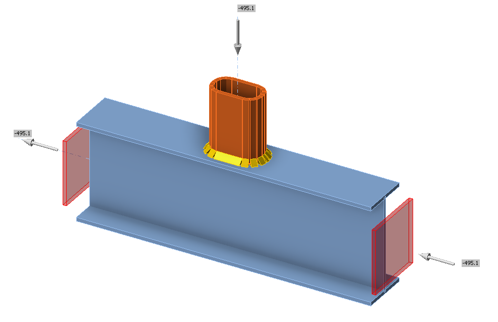
ฐานเสา
คำอธิบาย
ในบทนี้ วิธี Component-based Finite Element Method (CBFEM) ของฐานคอลัมน์ภายใต้คอลัมน์หน้าตัดเปิดเหล็กที่รับแรงอัดล้วนได้รับการตรวจสอบโดยเปรียบเทียบกับวิธีส่วนประกอบ (CM) การศึกษานี้จัดทำขึ้นสำหรับหน้าตัดคอลัมน์ ขนาดของแผ่นฐาน เกรดของ Concrete และขนาดของบล็อก Concrete
วิธีส่วนประกอบ
มีการพิจารณาส่วนประกอบสามส่วน ได้แก่ ปีกและเอวคอลัมน์รับแรงอัด Concrete รับแรงอัดรวมถึงวัสดุรองพื้น และรอยเชื่อม ส่วนประกอบปีกและเอวคอลัมน์รับแรงอัดได้รับการอธิบายใน EN 1993-1-8:2005 ข้อ 6.2.6.7 Concrete รับแรงอัดรวมถึงวัสดุรองพื้นได้รับการจำลองตาม EN 1993-1-8:2005 ข้อ 6.2.6.9 และ EN 1992-1-1:2005 ข้อ 6.7 ใช้การวนซ้ำสองรอบของพื้นที่ประสิทธิผลเพื่อกำหนดความต้านทาน
รอยเชื่อมได้รับการออกแบบรอบหน้าตัดคอลัมน์ ดู EN 1993-1-8:2005 ข้อ 4.5.3.2(6) ความหนาของรอยเชื่อมที่ปีกถูกเลือกให้เท่ากับความหนาของรอยเชื่อมที่เอว แรงเฉือนถ่ายผ่านเฉพาะรอยเชื่อมที่เอว และพิจารณาการกระจายความเค้นแบบพลาสติก
แผ่นฐานภายใต้ HEB 240
การศึกษานี้มุ่งเน้นที่ส่วนประกอบ Concrete รับแรงอัดรวมถึงวัสดุรองพื้น ตัวอย่างการคำนวณแสดงด้านล่างสำหรับบล็อก Concrete ที่มีขนาด a' = 1000 mm, b' = 1500 mm, h = 800 mm จาก Concrete เกรด C20/25 พร้อมแผ่นฐานที่มีขนาด a = 330 mm, b = 440 mm, t = 20 mm จากเหล็กเกรด S235 ดูรูปที่ 8.1.2
ความแข็งแรงของจุดต่อของ Concrete คำนวณภายใต้พื้นที่ประสิทธิผลในการรับแรงอัดรอบหน้าตัด ดูรูปที่ 8.1.1 โดยวนซ้ำสองขั้นตอน
สำหรับขั้นตอนที่ 1st คือ:
และสำหรับขั้นตอนที่ 2nd คือ:
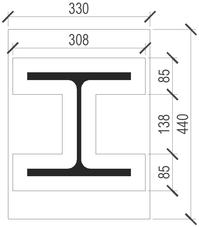
รูปที่ 8.1.1 พื้นที่ประสิทธิผลใต้แผ่นฐาน
ความต้านทานแรงปกติของแผ่นฐานโดย CM คือ
ความเค้นที่คำนวณโดย CBFEM แสดงในรูปที่ 8.1.2 ความต้านทานแรงอัดปกติของแผ่นฐานโดย CBFEM คือ 1683 kN
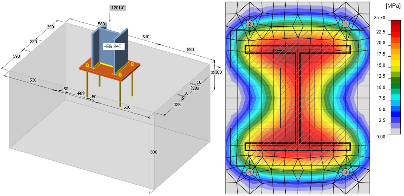
รูปที่ 8.1.2 รูปทรงของบล็อก Concrete และความเค้นปกติใต้แผ่นฐานที่รับเฉพาะแรงปกติ
การศึกษาความไว
ผลลัพธ์ของซอฟต์แวร์ CBFEM ถูกเปรียบเทียบกับผลลัพธ์ของวิธีส่วนประกอบ การเปรียบเทียบมุ่งเน้นที่ความต้านทานและส่วนประกอบวิกฤต พารามิเตอร์ที่ศึกษา ได้แก่ ขนาดของคอลัมน์ ขนาดของแผ่นฐาน เกรด Concrete และขนาดของแผ่นรอง Concrete หน้าตัดคอลัมน์ที่ใช้คือ HEB 200, HEB 300 และ HEB 400 ความกว้างและความยาวของแผ่นฐานถูกเลือกให้ใหญ่กว่าหน้าตัดคอลัมน์ 100 mm, 150 mm และ 200 mm ความหนาของแผ่นฐาน 15 mm, 20 mm และ 25 mm บล็อก Concrete จากเกรด C16/20, C25/30 และ C35/45 ที่ความสูง 800 mm โดยมีความกว้างและความยาวใหญ่กว่าขนาดของแผ่นฐาน 200 mm, 300 mm และ 400 mm พารามิเตอร์นำเข้าสรุปไว้ในตารางที่ 8.1.1 รอยเชื่อมมุมรอบหน้าตัดคอลัมน์มีความหนาคอ a = 8 mm
ตารางที่ 8.1.1 พารามิเตอร์ที่เลือก
| หน้าตัดคอลัมน์ | HEB 200 | HEB 300 | HEB 400 |
| ระยะยื่นของแผ่นฐาน | 100 mm | 150 mm | 200 mm |
| ความหนาของแผ่นฐาน | 15 mm | 20 mm | 25 mm |
| เกรด Concrete | C16/20 | C25/30 | C35/45 |
| ระยะยื่นของแผ่นรอง Concrete | 200 mm | 300 mm | 400 mm |
ความต้านทานที่กำหนดโดย CM แสดงในตารางที่ 8.1.2 พารามิเตอร์หนึ่งถูกเปลี่ยนแปลง และพารามิเตอร์อื่นๆ ถูกคงไว้ที่ค่ากลาง NRd คือความต้านทานของส่วนประกอบ Concrete รับแรงอัดรวมถึงวัสดุรองพื้น Fc,fc,Rd คือความต้านทานของส่วนประกอบปีกและเอวคอลัมน์รับแรงอัด และ Fc,weld คือความต้านทานของรอยเชื่อมโดยพิจารณาการกระจายความเค้นสม่ำเสมอ ใช้สัมประสิทธิ์จุดต่อ βj = 0,67
ตารางที่ 8.1.2 ผลลัพธ์ของวิธีส่วนประกอบ
| คอลัมน์ | ระยะยื่น B.p. [mm] | ความหนา B.p. [mm] | Concrete | ระยะยื่น C.b. [mm] | NRd [kN] | 2.Fc,fc,Rd [kN] | Fc,weld [kN] |
| HEB 200 | 150 | 20 | C25/30 | 300 | 1753 | 1632 | 2454 |
| HEB 300 | 150 | 20 | C25/30 | 300 | 2352 | 3126 | 3466 |
| HEB 400 | 150 | 20 | C25/30 | 300 | 2579 | 4040 | 3822 |
| HEB 300 | 100 | 20 | C25/30 | 300 | 2296 | 3126 | 3466 |
| HEB 300 | 200 | 20 | C25/30 | 300 | 2408 | 3126 | 3466 |
| HEB 300 | 150 | 15 | C25/30 | 300 | 1909 | 3126 | 3466 |
| HEB 300 | 150 | 25 | C25/30 | 300 | 2795 | 3126 | 3466 |
| HEB 300 | 150 | 20 | C16/20 | 300 | 1789 | 3126 | 3466 |
| HEB 300 | 150 | 20 | C35/45 | 300 | 2908 | 3126 | 3466 |
| HEB 300 | 150 | 20 | C25/30 | 200 | 2064 | 3126 | 3466 |
| HEB 300 | 150 | 20 | C25/30 | 400 | 2517 | 3126 | 3466 |
แบบจำลองใน CBFEM ถูกโหลดด้วยแรงอัดจนกระทั่งบล็อก Concrete ใกล้เคียง 100 % วิธีการเดียวกันนี้ถูกใช้เพื่อหาความต้านทานของรอยเชื่อม Fc,weld
ตารางที่ 8.1.3 ผลลัพธ์ของ CBFEM
| คอลัมน์ | ระยะยื่น B.p. [mm] | ความหนา B.p. [mm] | เกรด Concrete | ระยะยื่น C.b. [mm] | บล็อก Concrete [kN] | Fc,weld หรือ Fc,Rd [kN] |
| HEB 200 | 150 | 20 | C25/30 | 300 | 1565 | 1835 |
| HEB 300 | 150 | 20 | C25/30 | 300 | 2380 | 3205 |
| HEB 400 | 150 | 20 | C25/30 | 300 | 2710 | 3650 |
| HEB 300 | 100 | 20 | C25/30 | 300 | 2385 | 3205 |
| HEB 300 | 200 | 20 | C25/30 | 300 | 2420 | 3205 |
| HEB 300 | 150 | 15 | C25/30 | 300 | 1870 | 3204 |
| HEB 300 | 150 | 25 | C25/30 | 300 | 2915 | 3204 |
| HEB 300 | 150 | 20 | C16/20 | 300 | 1850 | 3205 |
| HEB 300 | 150 | 20 | C35/45 | 300 | 2975 | 3205 |
| HEB 300 | 150 | 20 | C25/30 | 200 | 2380 | 3205 |
| HEB 300 | 150 | 20 | C25/30 | 400 | 2420 | 3205 |
สรุป
การตรวจสอบ CBFEM เทียบกับ CM สำหรับแผ่นฐานที่รับแรงอัดแสดงในรูปที่ 8.1.3 เส้นประสอดคล้องกับค่าความต้านทาน 110% และ 90 % ความแตกต่างอยู่ที่สูงสุด 14 % เนื่องจากการประเมินกำลังรับแรงแบกทานของจุดต่อและพื้นที่ประสิทธิผลที่แม่นยำกว่าใน CBFEM
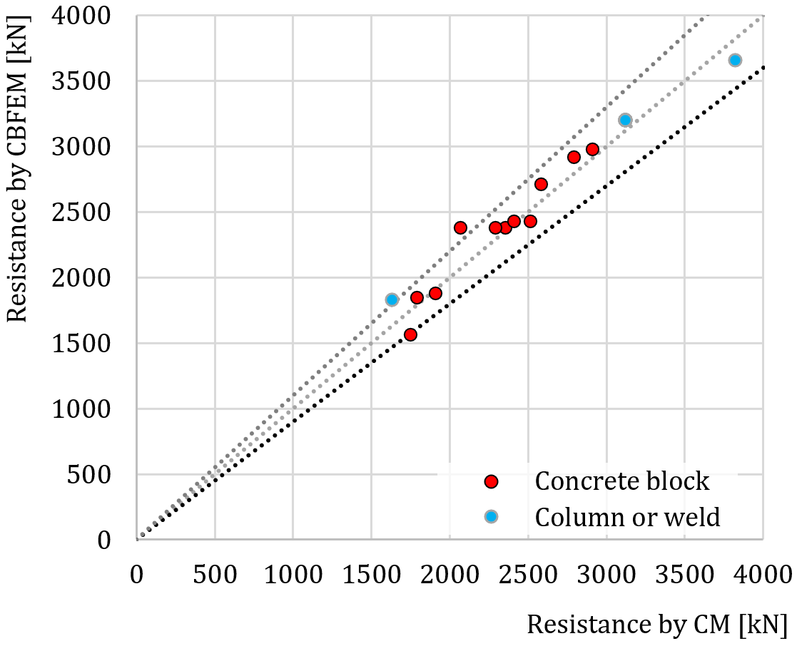
รูปที่ 8.1.3 การตรวจสอบ CBFEM เทียบกับ CM สำหรับแผ่นฐานที่รับแรงอัด
กรณีเกณฑ์มาตรฐาน
ข้อมูลนำเข้า
หน้าตัดคอลัมน์
- HEB 240
- เหล็ก S235
แผ่นฐาน
- ความหนา 20 mm
- ระยะยื่นด้านบน 100 mm, ด้านซ้าย 45 mm
- เหล็ก S235
บล็อก Concrete ฐานราก
- Concrete C20/25
- ระยะยื่น 335 mm, 530 mm
- ความลึก 800 mm
- ความหนาวัสดุรองพื้น 30 mm
สลักยึด
- M20 8.8
ผลลัพธ์
- ความต้านทานแรงตามแนวแกน Nj.Rd = −1683 kN
คำอธิบาย
วัตถุประสงค์ของบทนี้คือการตรวจสอบวิธี Component-Based Finite Element (CBFEM) ของฐานคอลัมน์ของคอลัมน์หน้าตัดเปิดเหล็กที่รับแรงอัดและแรงดัดรอบแกนแข็ง โดยเปรียบเทียบกับวิธี Component Method (CM) การศึกษานี้จัดทำขึ้นสำหรับขนาดของคอลัมน์ รูปทรงเรขาคณิต และความหนาของแผ่นฐาน ในการศึกษานี้ มีการตรวจสอบห้าองค์ประกอบ ได้แก่ ปีกและเอวคอลัมน์รับแรงอัด Concrete รับแรงอัดรวมถึงวัสดุรองพื้น แผ่นฐานรับแรงดัด พุกรับแรงดึง และรอยเชื่อม องค์ประกอบทั้งหมดออกแบบตาม EN 1993-1-8:2005, EN 1992‑1‑1:2005 และ EN 1992‑4
การตรวจสอบความต้านทาน
ตัวอย่างการออกแบบด้วยวิธี Component Method แสดงบนการยึดเหนี่ยวของหน้าตัดเหล็กคอลัมน์ HEB 240:
บล็อก Concrete มีขนาด a' = 1000 mm, b' = 1500 mm, h = 900 mm และเกรด C20/25 ขนาดแผ่นฐานคือ a = 330 mm, b = 440 mm, t = 20 mm และเกรดเหล็กคือ S235 สลักยึดเป็น 4 × M20, As = 245 mm2, ความยาว 300 mm พร้อมเส้นผ่านศูนย์กลางหัว a = 60 mm และเกรดเหล็ก 8.8 ความหนาของวัสดุรองพื้นคือ 30 mm
ผลลัพธ์ของการแก้ปัญหาเชิงวิเคราะห์สามารถนำเสนอบนแผนภาพปฏิสัมพันธ์ที่มีจุดสำคัญที่โดดเด่น จุด −1 แทนการรับแรงดึงล้วน และจุด 4 แทนความต้านทานการรับแรงอัด คำอธิบายโดยละเอียดของจุด 0, 1, 2 และ 3 แสดงในรูปที่ 8.2.1 ดู (Wald, 1995) และ (Wald et al. 2008)
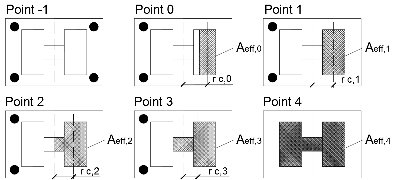
รูปที่ 8.2.1 จุดสำคัญบนแผนภาพปฏิสัมพันธ์
การกระจายความเค้นสำหรับจุด 0 และ 3 ที่ได้จาก CBFEM แสดงในรูปที่ 8.2.2 และ 8.2.3
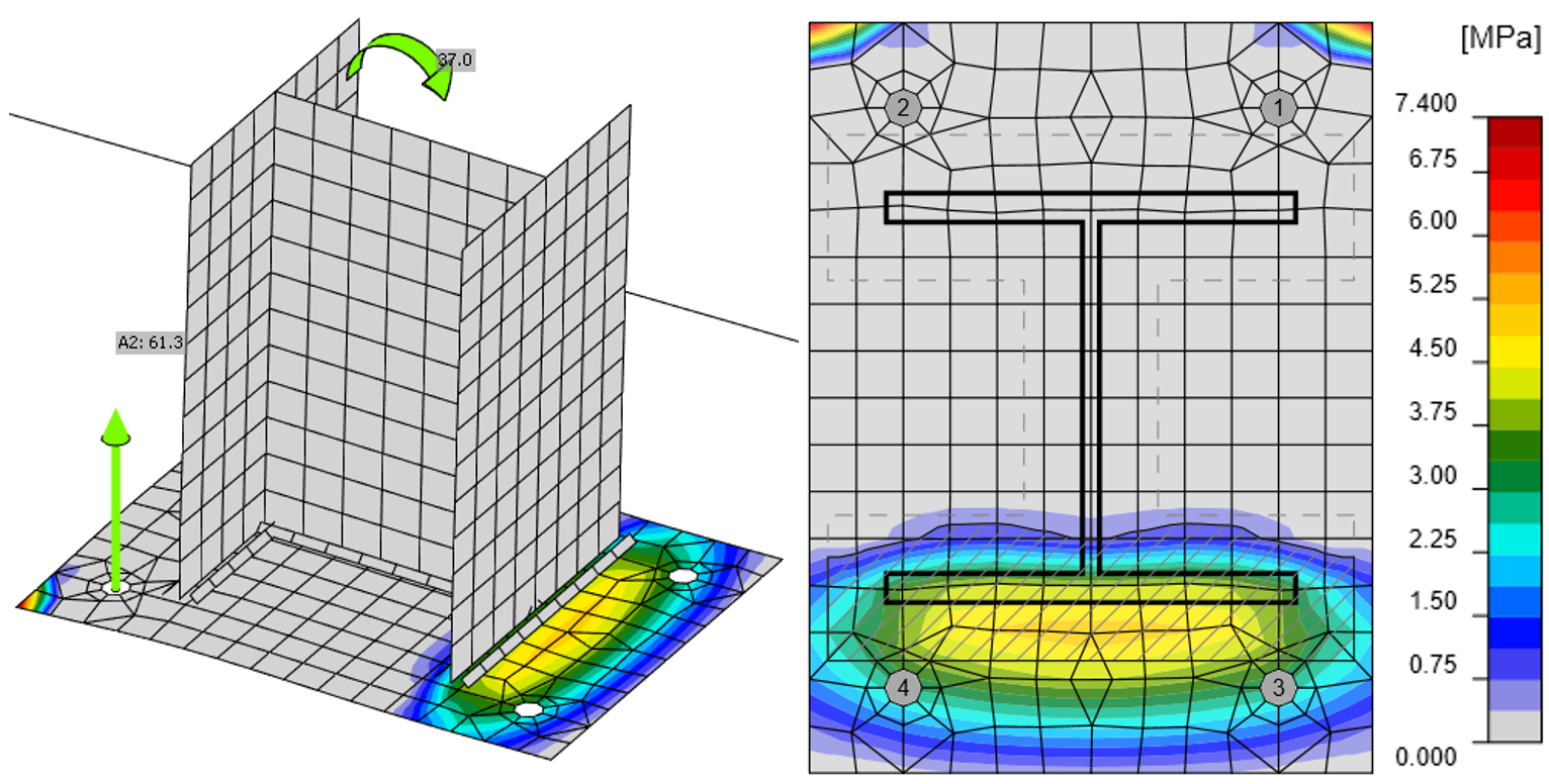
รูปที่ 8.2.2 ความเค้นใน Concrete และแรงในพุกสำหรับจุด 0 ที่ได้จาก CBFEM (มาตราส่วนการเสียรูป 10)
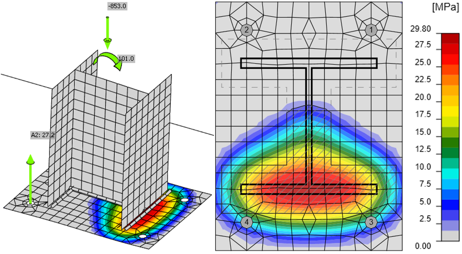
รูปที่ 8.2.3 ความเค้นใน Concrete และแรงในพุกสำหรับจุด 3 ที่ได้จาก CBFEM
(มาตราส่วนการเสียรูป 10)
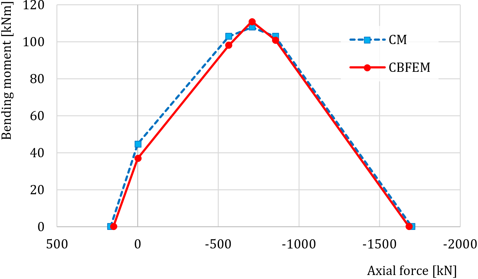
รูปที่ 8.2.4 การเปรียบเทียบแบบจำลองบนแผนภาพปฏิสัมพันธ์
การเปรียบเทียบแผนภาพปฏิสัมพันธ์ที่ได้จาก CBFEM กับแผนภาพปฏิสัมพันธ์ที่คำนวณตาม CM นำเสนอในรูปที่ 8.2.4 และตารางที่ 8.2.1
ตารางที่ 8.2.1 การเปรียบเทียบผลลัพธ์ของแผนภาพปฏิสัมพันธ์สำหรับ HEB 240 โดยการแก้ปัญหาเชิงวิเคราะห์และโดย CBFEM
| การแก้ปัญหาเชิงวิเคราะห์ | ผลลัพธ์ของ CBFEM | |||
| แรงตามแนวแกน [kN] | ความต้านทานแรงดัด [kNm] | แรงตามแนวแกน [kN] | ความต้านทานแรงดัด [kNm] | |
| จุด -1 | 169 | 0 | 150 | 0 |
| จุด 0 | 0 | 45 | 0 | 37 |
| จุด 1 | −564 | 103 | −564 | 98 |
| จุด 2 | −708 | 108 | −708 | 111 |
| จุด 3 | −853 | 103 | −853 | 101 |
| จุด 4 | −1700 | 0 | −1683 | 0 |
การศึกษาความไว
ผลลัพธ์ของ CBFEM ถูกเปรียบเทียบกับผลลัพธ์ของวิธี Component Method การเปรียบเทียบทำโดยใช้ความต้านทานโมเมนต์ดัดสำหรับระดับแรงปกติที่กำหนดสำหรับแต่ละจุดของแผนภาพปฏิสัมพันธ์
ในการศึกษาความไว ขนาดของคอลัมน์ ขนาดของแผ่นฐาน และขนาดของฐาน Concrete ถูกเปลี่ยนแปลง หน้าตัดคอลัมน์ที่เลือกคือ HEB 200, HEB 300 และ HEB 400 ความกว้างและความยาวของแผ่นฐานถูกเลือกให้ใหญ่กว่าหน้าตัดคอลัมน์ 100 mm, 150 mm และ 200 mm ความหนาของแผ่นฐานคือ 15 mm, 20 mm และ 25 mm ฐาน Concrete เป็นเกรด C25/30 ความสูงของฐาน Concrete สำหรับทุกกรณีคือ 900 mm และความกว้างและความยาวใหญ่กว่าขนาดของแผ่นฐาน 200 mm สลักยึดเป็น M20 เกรด 8.8 ที่มีความลึกฝังตัว 300 mm พารามิเตอร์สรุปไว้ในตารางที่ 8.2.2 รอยเชื่อมเหมือนกันรอบหน้าตัดคอลัมน์ทั้งหมดโดยมีความหนาคอขวดเพียงพอเพื่อไม่ให้เป็นองค์ประกอบวิกฤต พารามิเตอร์หนึ่งถูกเปลี่ยนแปลงในขณะที่พารามิเตอร์อื่นๆ คงที่ที่ค่ากลาง
ตารางที่ 8.2.2 พารามิเตอร์ที่เลือก
| หน้าตัดคอลัมน์ | HEB 200 | HEB 300 | HEB 400 |
| ระยะยื่นของแผ่นฐาน | 100 mm | 150 mm | 200 mm |
| ความหนาของแผ่นฐาน | 15 mm | 20 mm | 25 mm |
ในรูปที่ 8.2.5 นำเสนอผลลัพธ์สำหรับการเปลี่ยนแปลงหน้าตัดคอลัมน์ ในรูปที่ 8.2.6 และรูปที่ 8.2.7 ระยะยื่นของแผ่นฐานและความหนาของแผ่นฐานถูกเปลี่ยนแปลงตามลำดับ
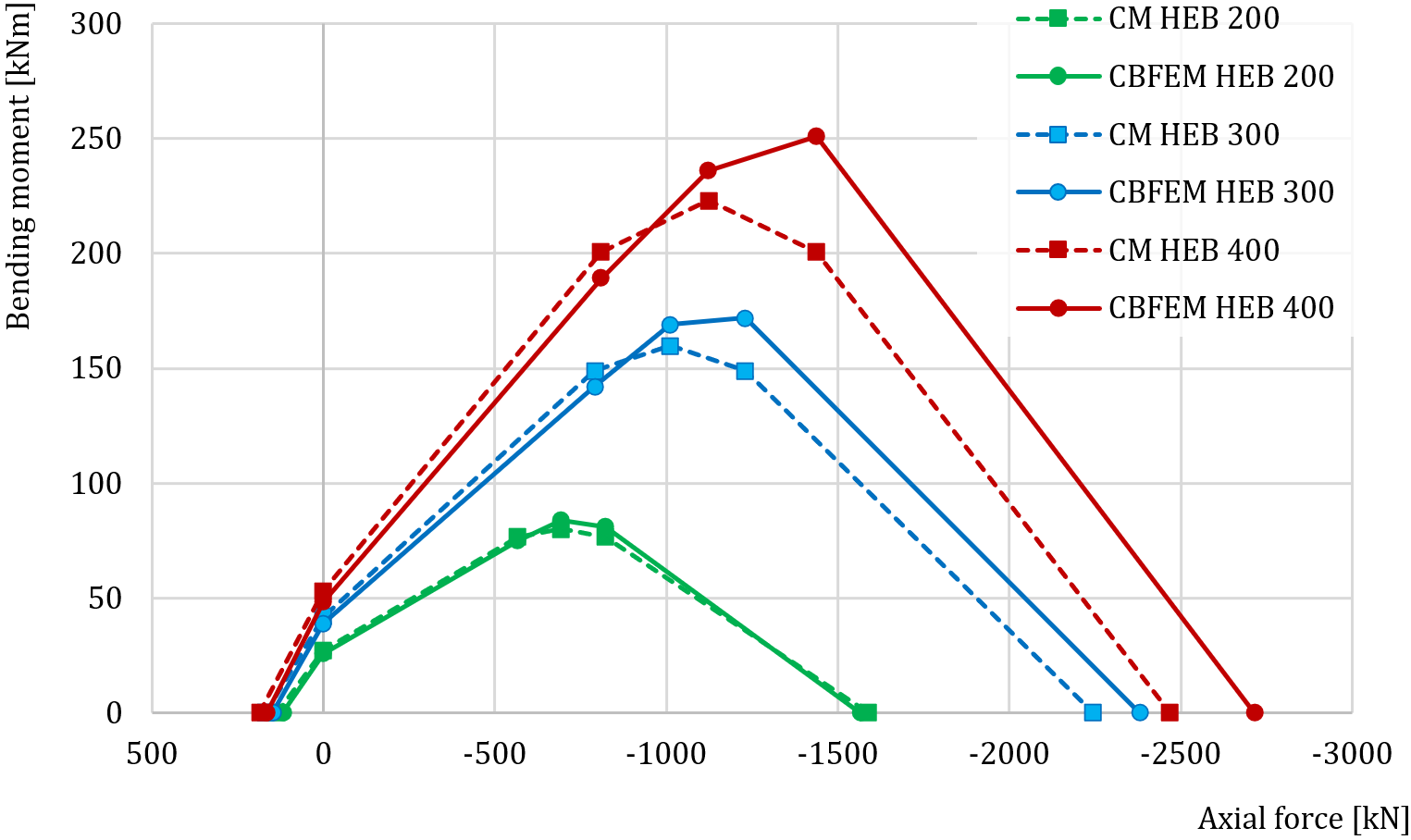
รูปที่ 8.2.5 การเปลี่ยนแปลงหน้าตัดคอลัมน์
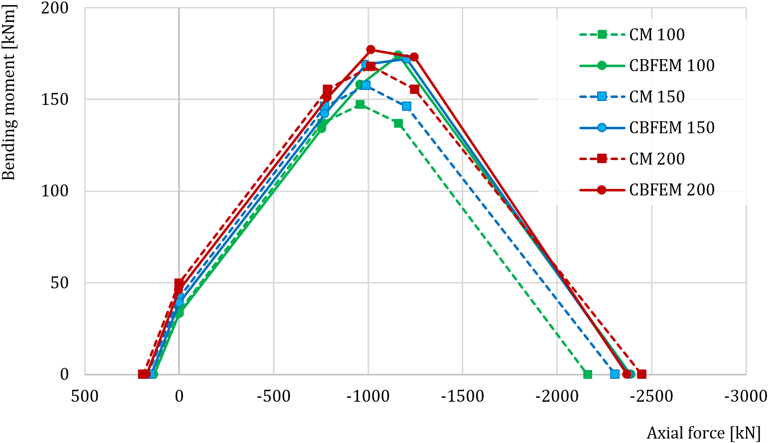
รูปที่ 8.2.6 การเปลี่ยนแปลงระยะยื่นของแผ่นฐาน – 100, 200 และ 300 mm
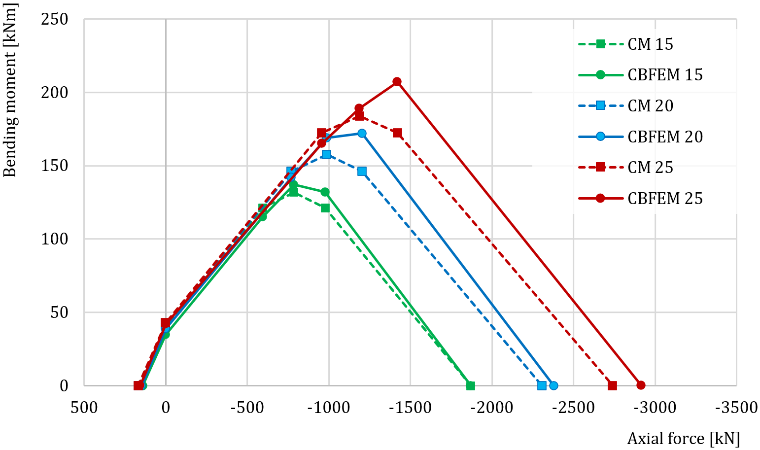
รูปที่ 8.2.7 การเปลี่ยนแปลงความหนาของแผ่นฐาน – 15, 20 และ 25 mm
กรณีเกณฑ์มาตรฐาน
ข้อมูลนำเข้า
หน้าตัดคอลัมน์
- HEB 240
- เหล็ก S235
แผ่นฐาน
- ความหนา 20 mm
- ระยะยื่นด้านบน 100 mm, ด้านซ้าย 45 mm
- เหล็ก S235
สลักยึด
- M20 8.8
- ความยาวยึดเหนี่ยว 300 mm
- ประเภทพุก: แผ่นรอง - วงกลม; ขนาด 40 mm
- ระยะยื่นแถวบน 50 mm, แถวซ้าย −10 mm
- ระนาบแรงเฉือนที่เกลียว
- รอยเชื่อมทั้งสองด้าน 8 mm
บล็อกฐานราก
- Concrete C20/25
- ระยะยื่น 335 mm และ 530 mm
- ความลึก 900 mm
- การถ่ายแรงเฉือนโดยแรงเสียดทาน
- ความหนาวัสดุรองพื้น 30 mm
แรงกระทำ
- แรงตามแนวแกน N = −853 kN
- โมเมนต์ดัด My = 100 kNm
ผลลัพธ์
- สลักยึด 42,2 % (NEd,g = 51,7 kN ≤ NRdc = 122,4 kN - การวิบัติแบบ Concrete core breakout สำหรับพุก A1 และ A2)
- บล็อก Concrete 99,5 % (σ = 26,7 MPa ≤ fjd = 26,8 MPa)
เอกสารอ้างอิง
EN 1992-1-1, Eurocode 2, Design of concrete structures – Part 1-1: General rules and rules for buildings, CEN, Brussels, 2005.
EN 1992-4:2018, Eurocode 2: Design of concrete structures – Part 4: Design of fastenings for use in concrete, Brussels, 2018.
EN 1993-1-8, Eurocode 3, Design of steel structures – Part 1-8: Design of joints, CEN, Brussels, 2005.
Wald F. Column Bases, CTU Publishing House, Prague, 1995.
Wald F., Sokol Z., Steenhuis M., Jaspart, J.P. Component method for steel column bases, Heron, 53, 2008, 3-20.
คำอธิบาย
วิธี Component-based finite element method (CBFEM) สำหรับฐานคอลัมน์หน้าตัดกลวง ที่ตรวจสอบเทียบกับวิธีส่วนประกอบ (CM) ได้อธิบายไว้ด้านล่าง คอลัมน์รับแรงอัดได้รับการออกแบบให้มีหน้าตัดอย่างน้อยชั้น 3 การศึกษาความไวได้จัดทำขึ้นสำหรับขนาดของคอลัมน์ ขนาดของแผ่นฐาน เกรดคอนกรีต และขนาดของบล็อกคอนกรีต มีการเปิดใช้งานส่วนประกอบสี่ส่วน ได้แก่ ปีกและเอวคอลัมน์รับแรงอัด คอนกรีตรับแรงอัดรวมถึงวัสดุรองพื้น สลักยึดรับแรงดึง และรอยเชื่อม การศึกษานี้มุ่งเน้นหลักที่สองส่วนประกอบ ได้แก่ คอนกรีตรับแรงอัดรวมถึงวัสดุรองพื้น และสลักยึดรับแรงดึง
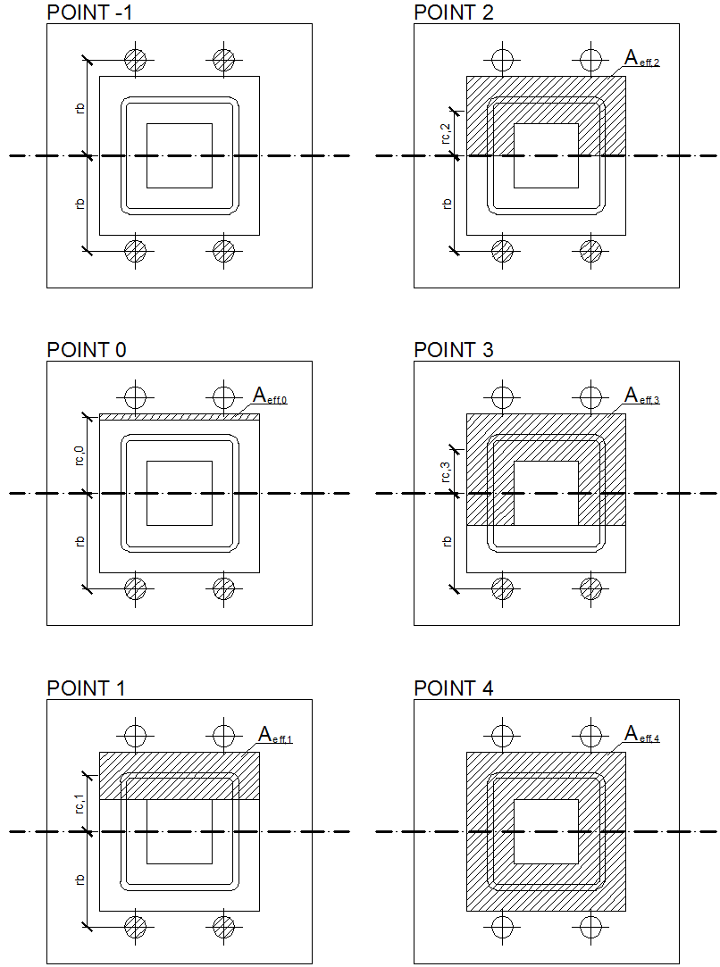
รูปที่ 8.4.1 จุดสำคัญของแผนภาพปฏิสัมพันธ์หลายเส้นตรงของหน้าตัดกลวงสี่เหลี่ยม
การตรวจสอบความต้านทาน
ในตัวอย่างต่อไปนี้ คอลัมน์จากหน้าตัดกลวงสี่เหลี่ยม SHS 150×16 ถูกเชื่อมต่อกับบล็อกคอนกรีตที่มีขนาดพื้นที่ a' = 750 มม., b' = 750 มม. และความสูง h = 800 มม. จากคอนกรีตเกรด C20/25 โดยใช้แผ่นฐาน a = 350 มม., b = 350 มม., t = 20 มม. จากเหล็กเกรด S420 สลักยึดได้รับการออกแบบเป็น 4 × M20, As = 245 มม.2 โดยมีเส้นผ่านศูนย์กลางหัว a = 60 มม. จากเหล็กเกรด 8.8 โดยมีระยะออฟเซ็ตที่ด้านบน 50 มม. และด้านซ้าย −20 มม. และมีความลึกฝัง 300 มม. วัสดุรองพื้นมีความหนา 30 มม.
ผลลัพธ์ของการแก้ปัญหาเชิงวิเคราะห์นำเสนอในรูปแบบแผนภาพปฏิสัมพันธ์ที่มีจุดเด่นชัด คำอธิบายโดยละเอียดของจุด −1, 0, 1, 2 และ 3 แสดงในรูปที่ 8.4.1 ดู (Wald, 1995) และ (Wald et al. 2008) โดยจุด −1 แทนแรงดึงล้วน จุด 0 แทนโมเมนต์ดัดล้วน จุด 1 ถึง 3 แทนแรงอัดและโมเมนต์ดัดรวมกัน และจุด 4 แทนแรงอัดล้วน
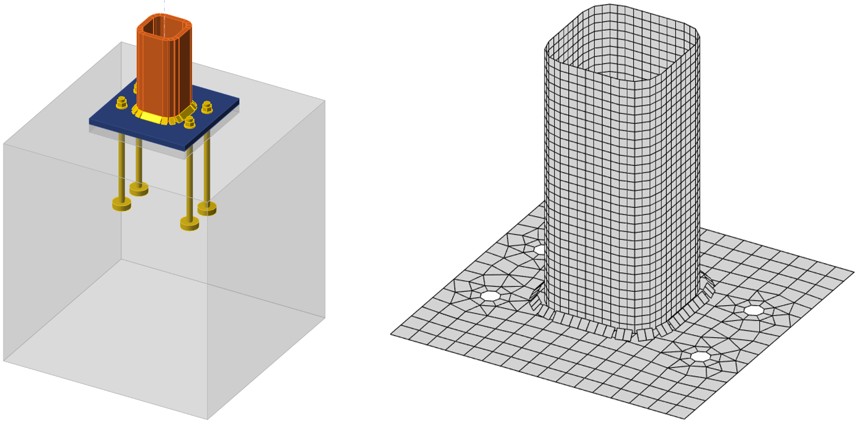
รูปที่ 8.4.2 ฐานคอลัมน์สำหรับคอลัมน์ SHS 150×16 และตาข่ายที่เลือกของแผ่นฐาน
ใน CBFEM แรงงัดเกิดขึ้นในกรณีที่รับแรงดึงล้วน ในขณะที่ใน CM ไม่มีการพัฒนาแรงงัดโดยการจำกัดความต้านทานให้อยู่ในรูปแบบการวิบัติ 1-2 เท่านั้น ดู (Wald et al. 2008) เนื่องจากแรงงัด ความแตกต่างของความต้านทานอยู่ที่ประมาณ 10 % แบบจำลองเชิงตัวเลขของฐานคอลัมน์แสดงในรูปที่ 8.4.2 ผลลัพธ์โดย CBFEM นำเสนอด้วยการกระจายความเค้นรองรับบนคอนกรีตสำหรับจุด 0 และ 3 แสดงในรูปที่ 8.4.3 และรูปที่ 8.4.4 และเปรียบเทียบบนแผนภาพปฏิสัมพันธ์ในรูปที่ 8.4.5
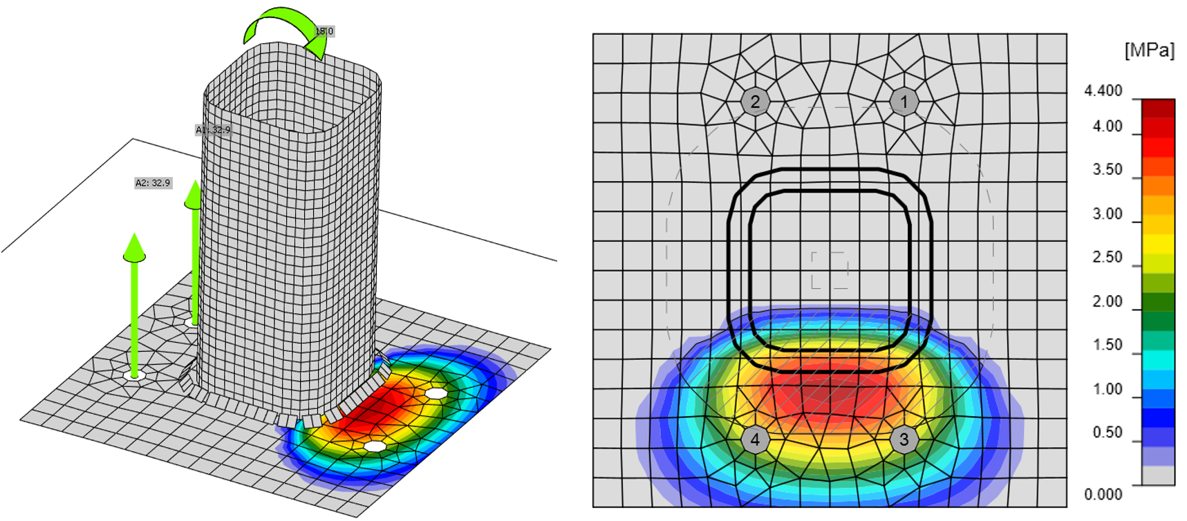
รูปที่ 8.4.3 ผลลัพธ์ CBFEM สำหรับจุด 0 คือโมเมนต์ดัดล้วน
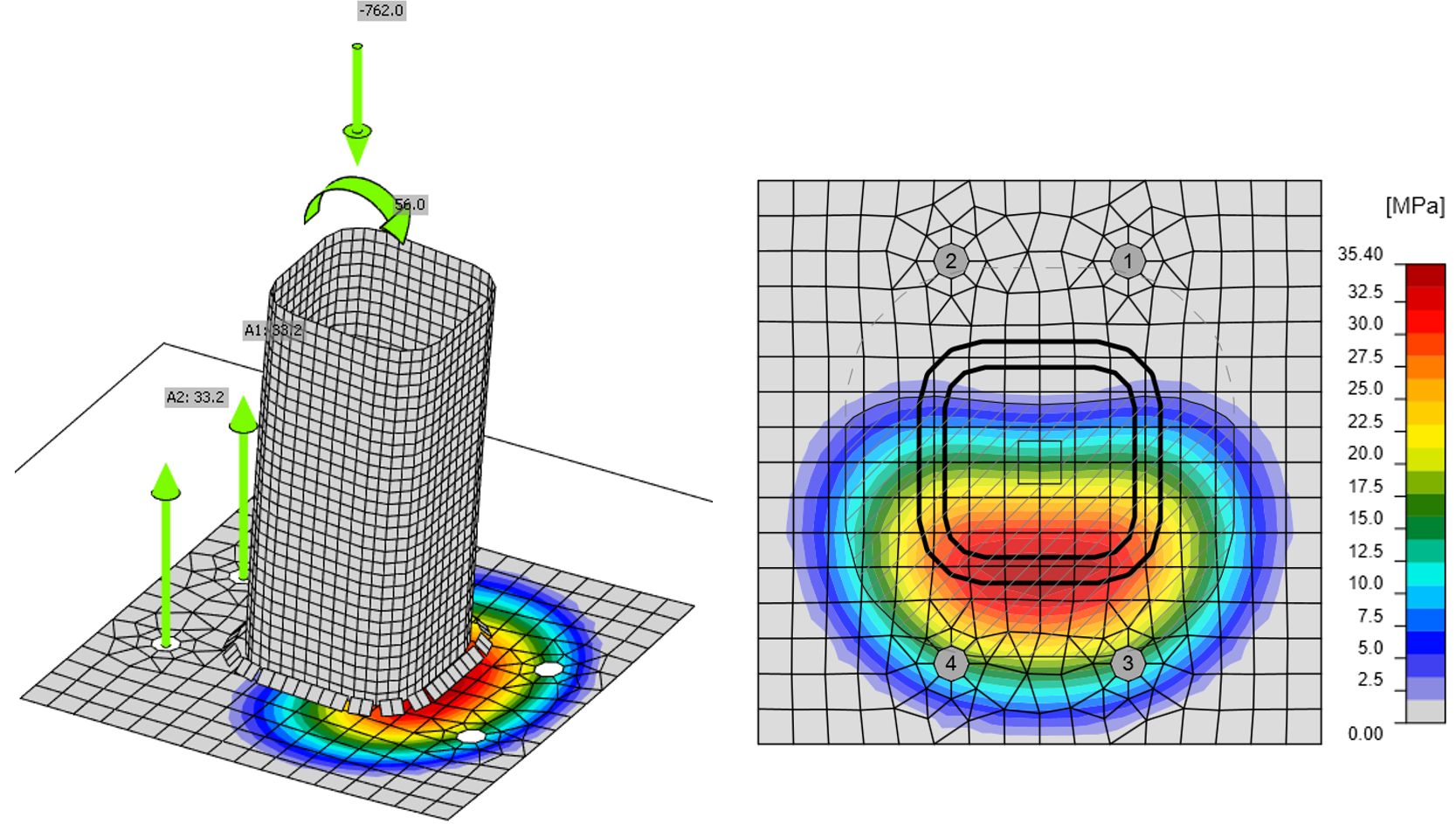
รูปที่ 8.4.4 ผลลัพธ์ CBFEM สำหรับจุด 3 คือแรงอัดและโมเมนต์ดัด
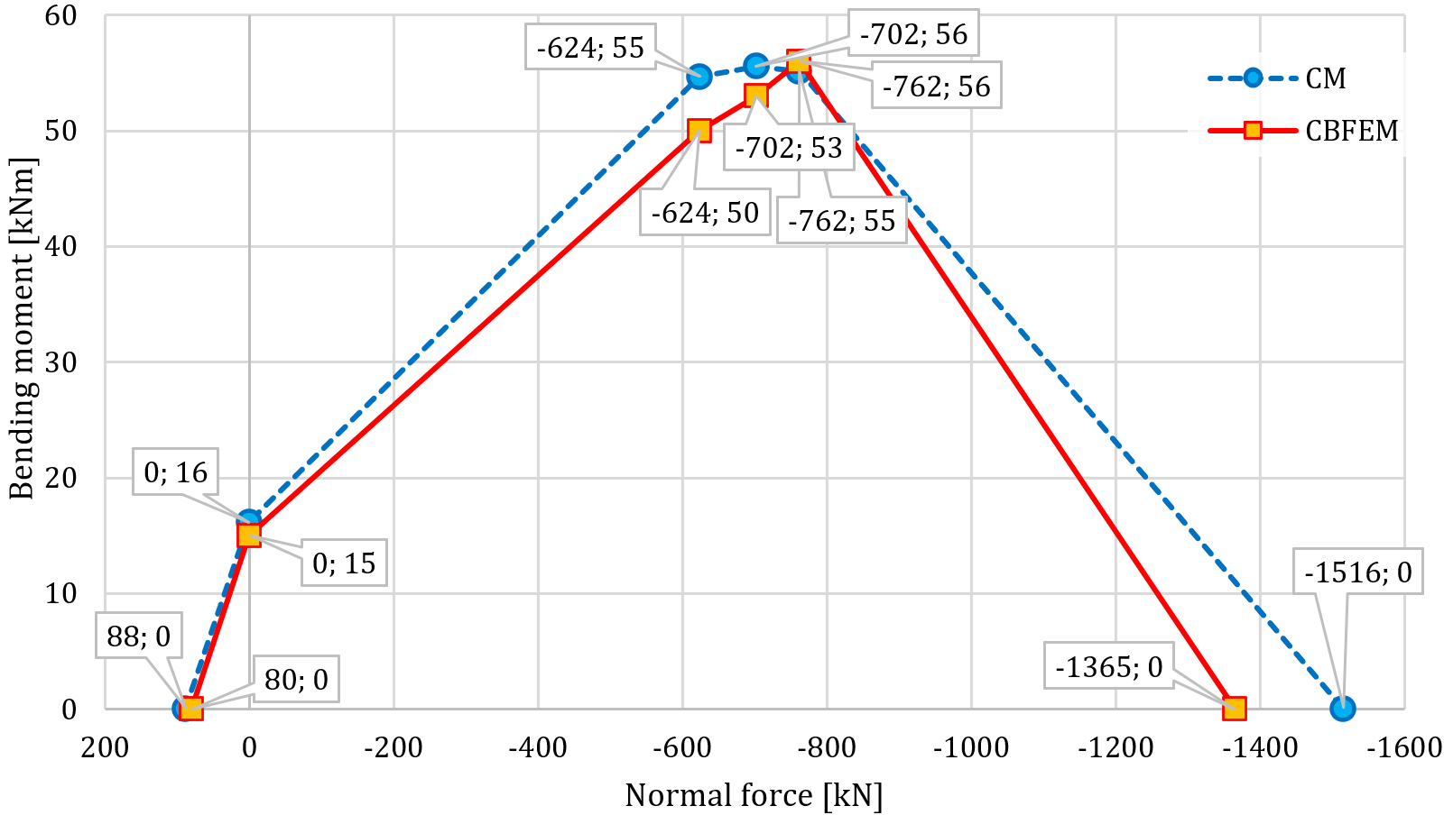
รูปที่ 8.4.5 การเปรียบเทียบผลลัพธ์การทำนายความต้านทานโดย CBFEM และ CM บนแผนภาพปฏิสัมพันธ์สำหรับฐานคอลัมน์หน้าตัด SHS 150×16
การศึกษาความไว
การศึกษาความไวได้จัดทำขึ้นสำหรับขนาดหน้าตัดคอลัมน์ ขนาดของแผ่นฐาน เกรดคอนกรีต และขนาดของบล็อกคอนกรีต คอลัมน์ที่เลือกได้แก่ SHS 150×16, SHS 160×12.5 และ SHS 200×16 แผ่นฐานได้รับการออกแบบโดยมีขนาดพื้นที่ใหญ่กว่าหน้าตัดคอลัมน์ 100 มม., 150 มม. และ 200 มม. ความหนาของแผ่นฐานคือ 10 มม., 20 มม. และ 30 มม. บล็อกฐานรากทำจากคอนกรีตเกรด C20/25, C25/30, C30/37 และ C35/45 โดยมีความสูงในทุกกรณี 800 มม. และมีขนาดพื้นที่ใหญ่กว่าขนาดแผ่นฐาน 100 มม., 200 มม., 300 มม. และ 500 มม. พารามิเตอร์หนึ่งถูกเปลี่ยนแปลงในขณะที่พารามิเตอร์อื่นคงที่ พารามิเตอร์สรุปไว้ในตารางที่ 8.4.1 รอยเชื่อมมุมที่มีความหนา a = 12 มม. ถูกเลือกใช้ ค่าสัมประสิทธิ์จุดต่อสำหรับวัสดุรองพื้นที่มีคุณภาพเพียงพอถูกกำหนดเป็น βj = 0,67 แผ่นเหล็กทำจาก S420 พร้อมสลักยึด M20 เกรด 8.8 ที่มีความลึกฝัง 300 มม. ในทุกกรณี
ตารางที่ 8.4.1 พารามิเตอร์ที่เลือก
| หน้าตัดคอลัมน์ | SHS 150×16 | SHS 16×12,5 | SHS 200×16 |
| ระยะออฟเซ็ตแผ่นฐาน, มม. | 100 | 150 | 200 |
| ความหนาแผ่นฐาน, มม. | 10 | 20 | 30 |
| เกรดคอนกรีต | C20/25 | C30/37 | C35/45 |
| ระยะออฟเซ็ตแผ่นคอนกรีต, มม. | 100 | 300 | 500 |
สำหรับการศึกษาความไวของหน้าตัดคอลัมน์ ได้ใช้คอนกรีตเกรด C20/25 ความหนาแผ่นฐาน 20 มม. ระยะออฟเซ็ตแผ่นฐาน 100 มม. และระยะออฟเซ็ตบล็อกคอนกรีต 200 มม. สำหรับการเปลี่ยนแปลงพารามิเตอร์ของหน้าตัดคอลัมน์ การเปรียบเทียบ CBFEM กับแบบจำลองเชิงวิเคราะห์โดย CM แสดงในแผนภาพปฏิสัมพันธ์ในรูปที่ 8.4.6
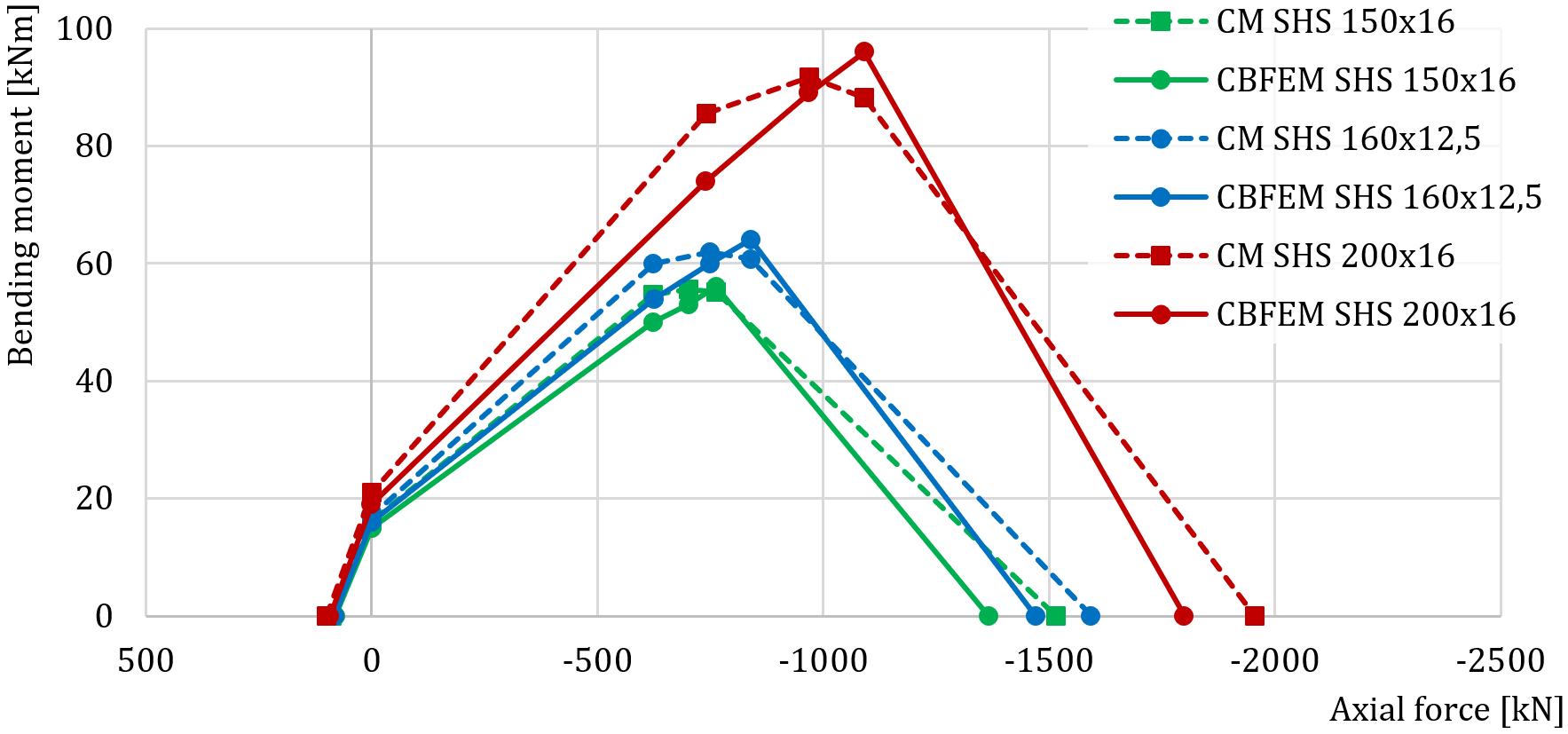
รูปที่ 8.4.6 การเปรียบเทียบผลลัพธ์ CBFEM กับ CM สำหรับหน้าตัดคอลัมน์ที่แตกต่างกัน
สำหรับการศึกษาความไวของระยะออฟเซ็ตแผ่นฐาน ได้เลือกหน้าตัดคอลัมน์ SHS 200×16 คอนกรีตเกรด C25/30 ความหนาแผ่นฐาน 20 มม. และระยะออฟเซ็ตบล็อกคอนกรีต 200 มม. การเปรียบเทียบแผนภาพปฏิสัมพันธ์แสดงในรูปที่ 8.4.7 ความแตกต่างที่มีนัยสำคัญที่สุดอยู่ที่ความต้านทานในแรงดึงล้วนของแผ่นฐานขนาดใหญ่ ซึ่งมีแรงงัดที่มีนัยสำคัญในการวิเคราะห์ CBFEM ซึ่งถูกจำกัดโดยการออกแบบเชิงวิเคราะห์
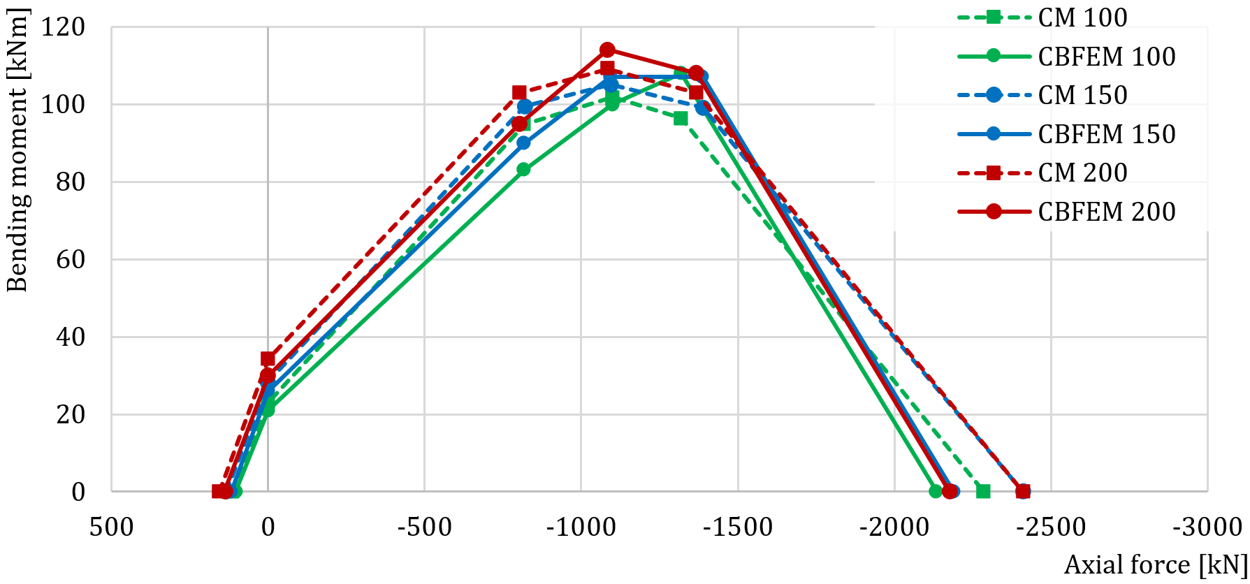
รูปที่ 8.4.7 การเปรียบเทียบผลลัพธ์ CBFEM กับ CM สำหรับระยะออฟเซ็ตแผ่นฐานที่แตกต่างกัน
สำหรับการศึกษาความไวของความหนาแผ่นฐาน ได้เลือกหน้าตัดคอลัมน์ SHS 200×16 คอนกรีตเกรด C25/30 ระยะออฟเซ็ตแผ่นฐาน 100 มม. และระยะออฟเซ็ตบล็อกคอนกรีต 200 มม. ความหนาแผ่นฐาน 10 มม., 20 มม. และ 30 มม. ถูกใช้ในการศึกษานี้ การเปรียบเทียบแผนภาพปฏิสัมพันธ์แสดงในรูปที่ 8.4.8 ความแตกต่างที่ใหญ่ที่สุดอยู่ที่ความต้านทานในแรงดึงล้วนของแผ่นฐานบาง ซึ่งมีแรงงัดที่มีนัยสำคัญในการวิเคราะห์ CBFEM ซึ่งถูกจำกัดในการออกแบบเชิงวิเคราะห์โดย CM
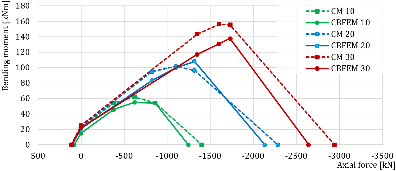
รูปที่ 8.4.8 การเปรียบเทียบผลลัพธ์ CBFEM กับ CM สำหรับความหนาแผ่นฐานที่แตกต่างกัน
สำหรับการศึกษาความไวของเกรดคอนกรีต ได้เลือกหน้าตัดคอลัมน์ SHS 150×16 ความหนาแผ่นฐาน 20 มม. ระยะออฟเซ็ตแผ่นฐาน 100 มม. และระยะออฟเซ็ตบล็อกคอนกรีต 200 มม. คอนกรีตเกรด C20/25, C30/37 และ C35/45 ถูกใช้ในการศึกษานี้ การเปรียบเทียบแผนภาพปฏิสัมพันธ์แสดงในรูปที่ 8.4.9
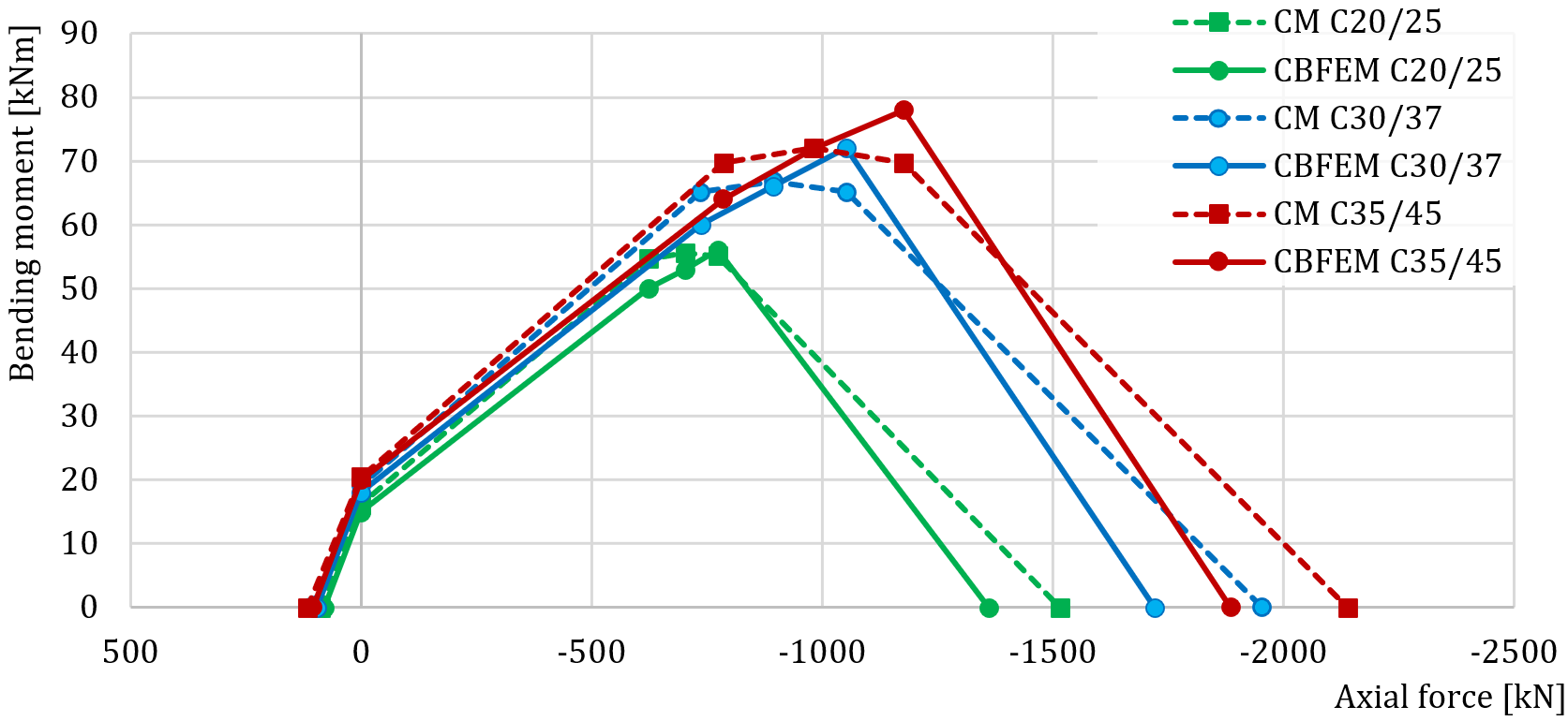
รูปที่ 8.4.9 การเปรียบเทียบผลลัพธ์ CBFEM กับ CM สำหรับเกรดคอนกรีตที่แตกต่างกัน
สำหรับการศึกษาความไวของระยะออฟเซ็ตบล็อกคอนกรีต ได้เลือกหน้าตัดคอลัมน์ SHS 160×12.5 ความหนาแผ่นฐาน 20 มม. ระยะออฟเซ็ตแผ่นฐาน 100 มม. และคอนกรีตเกรด C25/30 ระยะออฟเซ็ตบล็อกคอนกรีต 100 มม., 300 มม. และ 500 มม. ถูกใช้ในการศึกษานี้ การเปรียบเทียบแผนภาพปฏิสัมพันธ์แสดงในรูปที่ 8.4.10
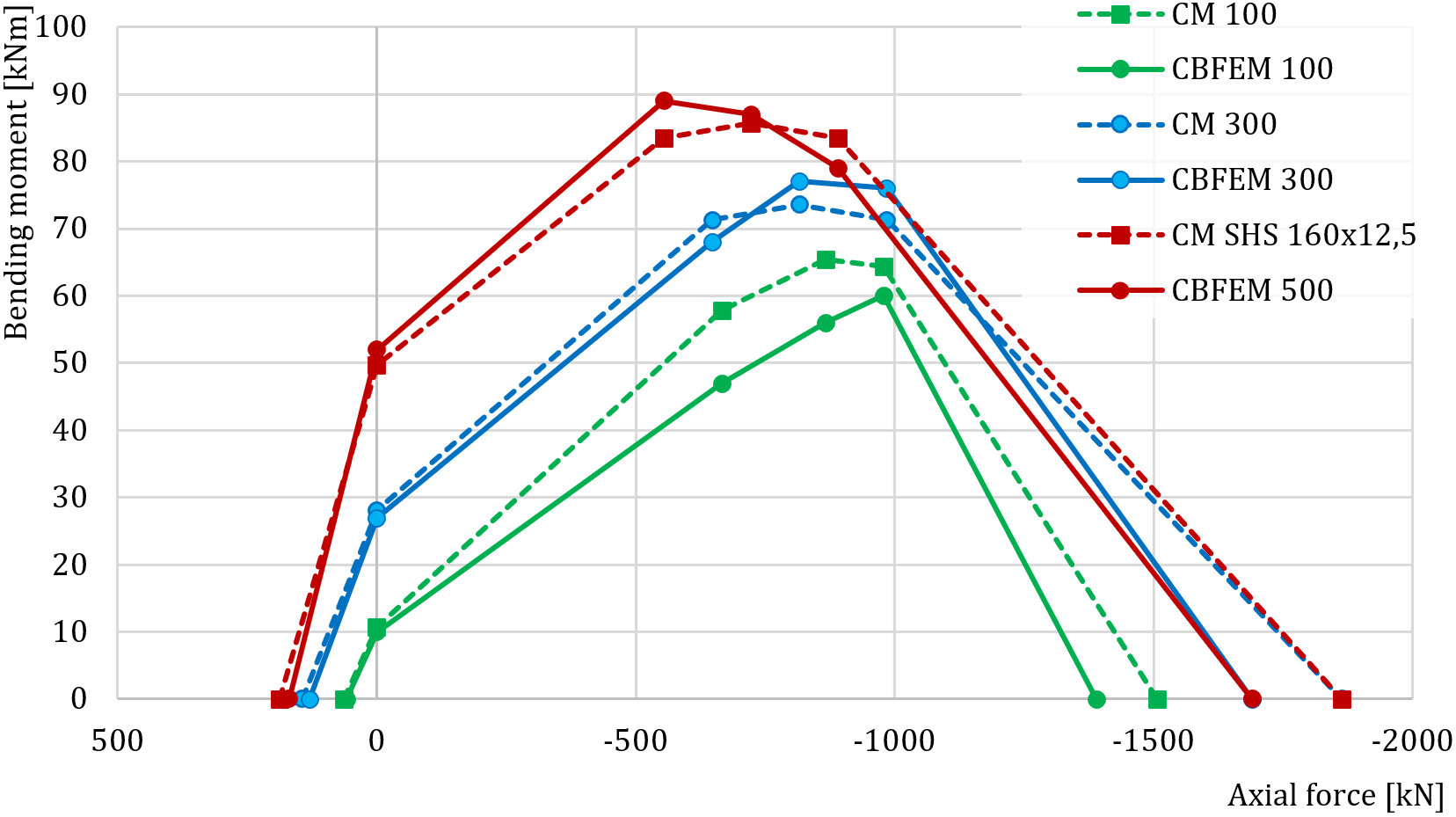
รูปที่ 8.4.10 การเปรียบเทียบผลลัพธ์ CBFEM กับ CM สำหรับระยะออฟเซ็ตบล็อกคอนกรีตที่แตกต่างกัน
ความแตกต่างในการทำนายความต้านทานของฐานคอลัมน์โดย CBFEM และ CM ส่วนใหญ่อยู่ที่การยอมรับแรงงัดใน CBFEM และการหลีกเลี่ยงแรงงัดโดย CM ตาม EN 1993-1-8:2005
ตารางที่ 8.4.2 การเปรียบเทียบแผนภาพปฏิสัมพันธ์ของ CBFEM และ CM
| ความแตกต่าง CBFEM/CM | จุด -1 | จุด 0 | จุด 1 | จุด 2 | จุด 3 | จุด 4 |
| สูงสุด % | 100% | 105% | 107% | 105% | 112% | 93% |
| ต่ำสุด % | 69% | 71% | 81% | 84% | 89% | 88% |
กรณีทดสอบมาตรฐาน
ข้อมูลนำเข้า
หน้าตัดคอลัมน์
- SHS 150×16
- เหล็ก S420
แผ่นฐาน
- ความหนา 20 มม.
- ระยะออฟเซ็ตด้านบน 100 มม., ด้านซ้าย 100 มม.
- รอยเชื่อม – รอยเชื่อมชน
- เหล็ก S420
สลักยึด
- M20 8.8.
- ความยาวยึดเหนี่ยว 300 มม.
- ประเภทสลักยึด: แผ่นรอง - วงกลม; ขนาด 40 มม.
- ระยะออฟเซ็ตชั้นบน 50 มม., ชั้นซ้าย −20 มม.
- ระนาบแรงเฉือนที่เกลียว
บล็อกฐานราก
- คอนกรีต C20/25
- ระยะออฟเซ็ต 200 มม.
- ความลึก 800 มม.
- การถ่ายแรงเฉือนโดยแรงเสียดทาน
- ความหนาวัสดุรองพื้น 30 มม.
แรงกระทำ
- แรงตามแนวแกน N = −762 kN
- โมเมนต์ดัด My = 56 kNm
ผลลัพธ์
- แผ่นเหล็ก
- สลักยึด 97,8 % ( (ส่วนประกอบวิกฤตคือการแตกร้าวรูปกรวยคอนกรีตสำหรับกลุ่มสลักยึด A1 และ A2)
- บล็อกคอนกรีต 91,5 % ()
- ความแข็งในการหมุนแบบ Secant
เอกสารอ้างอิง
EN 1993-1-8, Eurocode 3, การออกแบบโครงสร้างเหล็ก – ส่วนที่ 1-8: การออกแบบจุดต่อ, CEN, บรัสเซลส์, 2005.
Wald F. Column Bases, CTU Publishing House, ปราก, 1995.
Wald F., Sokol Z., Steenhuis M., Jaspart, J.P. Component method for steel column bases, Heron, 53, 2008, 3-20.
แผ่นเอวเสารับแรงเฉือน
คำอธิบาย
ในบทนี้ วิธี Component-Based Finite Element (CBFEM) สำหรับการเชื่อมต่อโมเมนต์ที่มุมหลังคาของโครงพอร์ทัลแบบเชื่อม ได้รับการตรวจสอบความถูกต้องโดยเปรียบเทียบกับวิธีส่วนประกอบ (CM) คานหน้าตัดเปิดถูกเชื่อมเข้ากับเสาหน้าตัดเปิด เสาได้รับการเสริมด้วยแผ่นเสริมความแข็งแนวนอนสองแผ่นตรงข้ามกับปีกคาน แผ่นที่รับแรงอัด เช่น แผ่นเสริมความแข็งแนวนอนของเสา แผ่นเอวเสาในการรับแรงเฉือน และปีกคานที่รับแรงอัด ถูกจำกัดให้อยู่ในชั้นที่ 3 เพื่อหลีกเลี่ยงการโก่งเดาะ คานจั่วรับแรงเฉือนและโมเมนต์ดัด
แบบจำลองเชิงวิเคราะห์
ส่วนประกอบห้าชิ้นได้รับการตรวจสอบในการศึกษานี้ ได้แก่ แผ่นเอวในการรับแรงเฉือน เอวเสาในการรับแรงอัดตามขวาง เอวเสาในการรับแรงดึงตามขวาง ปีกเสาในการรับโมเมนต์ดัด และปีกคานในการรับแรงอัด ส่วนประกอบทั้งหมดได้รับการออกแบบตาม EN 1993-1-8:2005 รอยเชื่อมมุมได้รับการออกแบบให้ไม่เป็นส่วนประกอบที่อ่อนแอที่สุดในจุดต่อ การศึกษาตรวจสอบความถูกต้องของรอยเชื่อมมุมในจุดต่อคาน-เสาที่มีแผ่นเสริมความแข็งอยู่ในบทที่ 4.4
แผ่นเอวในการรับแรงเฉือน
ความหนาของเอวเสาถูกจำกัดด้วยอัตราส่วนความชะลูดเพื่อหลีกเลี่ยงปัญหาเสถียรภาพ ดู EN 1993‑1‑8:2005, ข้อ 6.2.6.1(1) แผ่นเอวเสาชั้นที่ 4 ในการรับแรงเฉือนได้รับการศึกษาในบทที่ 6.2 พิจารณาการมีส่วนร่วมสองส่วนต่อความสามารถรับแรง ได้แก่ ความต้านทานของแผ่นเสาในการรับแรงเฉือน และการมีส่วนร่วมจากกลไกโครงของปีกเสาและแผ่นเสริมความแข็งแนวนอน ดู EN 1993‑1‑8:2005, ข้อ 6.2.6.1 (6.7 และ 6.8)
เอวเสาในการรับแรงอัดตามขวาง
พิจารณาผลของปฏิสัมพันธ์ของแรงเฉือน ดู EN 1993-1-8:2005, ข้อ 6.2.6.2, ตาราง 6.3 พิจารณาอิทธิพลของความเค้นตามแนวแกนในแผ่นเสา ดู EN 1993-1-8:2005, ข้อ 6.2.6.2(2) แผ่นเสริมความแข็งแนวนอนถูกรวมอยู่ในความสามารถรับแรงของส่วนประกอบนี้
เอวเสาในการรับแรงดึงตามขวาง
พิจารณาผลของปฏิสัมพันธ์ของแรงเฉือน ดู EN 1993-1-8:2005, ข้อ 6.2.6.2, ตาราง 6.3 แผ่นเสริมความแข็งแนวนอนถูกรวมอยู่ในความสามารถรับแรงของส่วนประกอบนี้
ปีกเสาในการรับโมเมนต์ดัด
แผ่นเสริมความแข็งแนวนอนค้ำยันปีกเสา ส่วนประกอบนี้จึงไม่ได้รับการพิจารณา
ปีกคานในการรับแรงอัด
คานแนวนอนได้รับการออกแบบให้เป็นหน้าตัดชั้นที่ 3 หรือดีกว่าเพื่อหลีกเลี่ยงการโก่งเดาะ
ภาพรวมของตัวอย่างที่พิจารณาและวัสดุแสดงไว้ในตาราง 9.1.1 รูปทรงเรขาคณิตของจุดต่อพร้อมขนาดแสดงในรูปที่ 9.1.1 พารามิเตอร์ที่พิจารณาในการศึกษา ได้แก่ หน้าตัดคาน หน้าตัดเสา และความหนาของแผ่นเอวเสา
ตาราง 9.1.1 ภาพรวมตัวอย่าง
| ตัวอย่าง | วัสดุ | คาน | เสา | แผ่นเสริมความแข็งเสา | |||||
| fy | fu | E | Section | Section | bs | ts | |||
| [MPa] | [MPa] | [GPa] | [-] | [-] | [mm] | [mm] | |||
| IPE140 | 235 | 360 | 210 | 1 | 1,25 | IPE140 | HEB260 | 73 | 10 |
| IPE160 | 235 | 360 | 210 | 1 | 1,25 | IPE160 | HEB260 | 82 | 10 |
| IPE180 | 235 | 360 | 210 | 1 | 1,25 | IPE180 | HEB260 | 91 | 10 |
| IPE200 | 235 | 360 | 210 | 1 | 1,25 | IPE200 | HEB260 | 100 | 10 |
| IPE220 | 235 | 360 | 210 | 1 | 1,25 | IPE220 | HEB260 | 110 | 10 |
| IPE240 | 235 | 360 | 210 | 1 | 1,25 | IPE240 | HEB260 | 120 | 10 |
| IPE270 | 235 | 360 | 210 | 1 | 1,25 | IPE270 | HEB260 | 135 | 10 |
| IPE300 | 235 | 360 | 210 | 1 | 1,25 | IPE300 | HEB260 | 150 | 10 |
| IPE330 | 235 | 360 | 210 | 1 | 1,25 | IPE330 | HEB260 | 160 | 10 |
| IPE360 | 235 | 360 | 210 | 1 | 1,25 | IPE360 | HEB260 | 170 | 10 |
| IPE400 | 235 | 360 | 210 | 1 | 1,25 | IPE400 | HEB260 | 180 | 10 |
| IPE450 | 235 | 360 | 210 | 1 | 1,25 | IPE450 | HEB260 | 190 | 10 |
| IPE500 | 235 | 360 | 210 | 1 | 1,25 | IPE500 | HEB260 | 200 | 10 |
| ตัวอย่าง | วัสดุ | คาน | เสา | แผ่นเสริมความแข็งเสา | |||||
| fy | fu | E | Section | Section | bs | ts | |||
| [MPa] | [MPa] | [GPa] | [-] | [-] | [mm] | [mm] | |||
| HEB160 | 235 | 360 | 210 | 1 | 1,25 | IPE330 | HEB160 | 160 | 10 |
| HEB180 | 235 | 360 | 210 | 1 | 1,25 | IPE330 | HEB180 | 160 | 10 |
| HEB200 | 235 | 360 | 210 | 1 | 1,25 | IPE330 | HEB200 | 160 | 10 |
| HEB220 | 235 | 360 | 210 | 1 | 1,25 | IPE330 | HEB220 | 160 | 10 |
| HEB240 | 235 | 360 | 210 | 1 | 1,25 | IPE330 | HEB240 | 160 | 10 |
| HEB260 | 235 | 360 | 210 | 1 | 1,25 | IPE330 | HEB260 | 160 | 10 |
| HEB280 | 235 | 360 | 210 | 1 | 1,25 | IPE330 | HEB280 | 160 | 10 |
| HEB300 | 235 | 360 | 210 | 1 | 1,25 | IPE330 | HEB300 | 160 | 10 |
| HEB320 | 235 | 360 | 210 | 1 | 1,25 | IPE330 | HEB320 | 160 | 10 |
| HEB340 | 235 | 360 | 210 | 1 | 1,25 | IPE330 | HEB340 | 160 | 10 |
| HEB360 | 235 | 360 | 210 | 1 | 1,25 | IPE330 | HEB360 | 160 | 10 |
| HEB400 | 235 | 360 | 210 | 1 | 1,25 | IPE330 | HEB400 | 160 | 10 |
| HEB500 | 235 | 360 | 210 | 1 | 1,25 | IPE330 | HEB500 | 160 | 10 |
| ตัวอย่าง | วัสดุ | คาน | เสา | แผ่นเสริมความแข็งเสา | ||||||
| fy | fu | E | Section | Section | tw | bs | ts | |||
| [MPa] | [MPa] | [GPa] | [-] | [-] | [mm] | [mm] | [mm] | |||
| tw4 | 235 | 360 | 210 | 1 | 1,25 | IPE330 | HEA320 | 4 | 160 | 10 |
| tw5 | 235 | 360 | 210 | 1 | 1,25 | IPE330 | HEA320 | 5 | 160 | 10 |
| tw6 | 235 | 360 | 210 | 1 | 1,25 | IPE330 | HEA320 | 6 | 160 | 10 |
| tw7 | 235 | 360 | 210 | 1 | 1,25 | IPE330 | HEA320 | 7 | 160 | 10 |
| tw8 | 235 | 360 | 210 | 1 | 1,25 | IPE330 | HEA320 | 8 | 160 | 10 |
| tw9 | 235 | 360 | 210 | 1 | 1,25 | IPE330 | HEA320 | 9 | 160 | 10 |
| tw10 | 235 | 360 | 210 | 1 | 1,25 | IPE330 | HEA320 | 10 | 160 | 10 |
| tw11 | 235 | 360 | 210 | 1 | 1,25 | IPE330 | HEA320 | 11 | 160 | 10 |
| tw12 | 235 | 360 | 210 | 1 | 1,25 | IPE330 | HEA320 | 12 | 160 | 10 |
| tw13 | 235 | 360 | 210 | 1 | 1,25 | IPE330 | HEA320 | 13 | 160 | 10 |
| tw14 | 235 | 360 | 210 | 1 | 1,25 | IPE330 | HEA320 | 14 | 160 | 10 |
| tw15 | 235 | 360 | 210 | 1 | 1,25 | IPE330 | HEA320 | 15 | 160 | 10 |
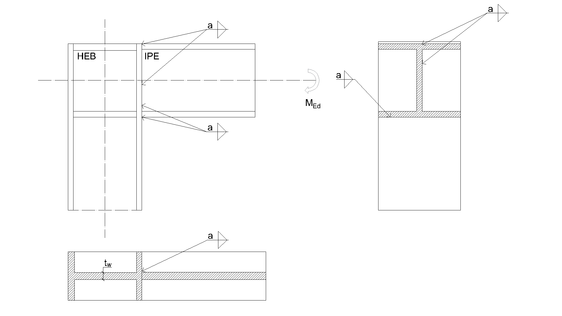
แบบจำลองเชิงตัวเลข
สถานะวัสดุแบบยืดหยุ่น-พลาสติกไม่เชิงเส้นได้รับการตรวจสอบในแต่ละชั้นของจุดอินทิเกรชัน การประเมินผลอ้างอิงจากค่าความเครียดสูงสุดตามที่กำหนดใน EN 1993-1-5:2006 ที่ค่า 5%
พฤติกรรมโดยรวม
นำเสนอการเปรียบเทียบพฤติกรรมโดยรวมของการเชื่อมต่อโมเมนต์โครงพอร์ทัล ซึ่งอธิบายด้วยแผนภาพโมเมนต์-การหมุน คุณลักษณะหลักของแผนภาพโมเมนต์-การหมุน ได้แก่ ความแข็งเริ่มต้น ความต้านทานยืดหยุ่น และความต้านทานการออกแบบ คานหน้าตัดเปิด IPE 330 ถูกเชื่อมเข้ากับเสา HEB 260 ในตัวอย่างนี้ การเชื่อมต่อโมเมนต์โครงพอร์ทัลที่มีแผ่นเสริมความแข็งแนวนอนในเสาได้รับการพิจารณาตามวิธีส่วนประกอบว่าเป็นจุดต่อแบบแข็งที่มี Sj,ini = ∞ ดังนั้นจึงวิเคราะห์จุดต่อที่ไม่มีแผ่นเสริมความแข็งแนวนอนในเสา แผนภาพโมเมนต์-การหมุนแสดงในรูปที่ 9.1.2 และผลลัพธ์สรุปไว้ในตาราง 9.1.2 ผลลัพธ์แสดงให้เห็นความสอดคล้องที่ดีมากในด้านความแข็งเริ่มต้นและพฤติกรรมโดยรวมของจุดต่อ
ตาราง 9.1.2 ความแข็งในการหมุนของการเชื่อมต่อโมเมนต์โครงพอร์ทัลใน CBFEM และ CM
| CM | CBFEM | CM/CBFEM | ||
| ความแข็งเริ่มต้น Sj,ini | [kNm/rad] | 48423,7 | 58400,0 | 0,83 |
| ความต้านทานยืดหยุ่น 2/3 Mj,Rd | [kNm] | 93,3 | 93,0 | 1,00 |
| ความต้านทานการออกแบบ Mj,Rd | [kNm] | 140,0 | 139,0 | 0,99 |
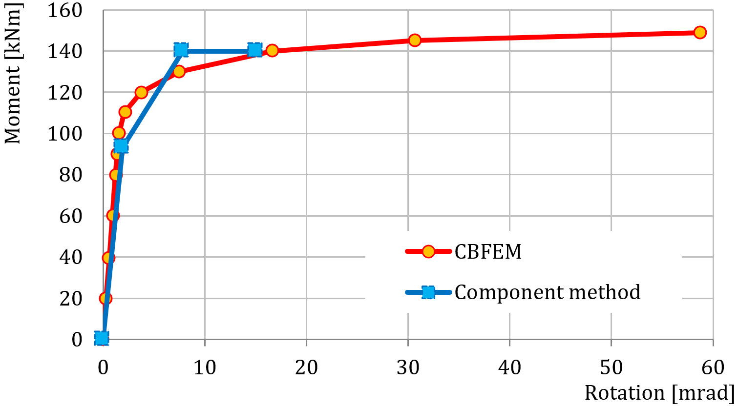
การตรวจสอบความต้านทาน
ผลลัพธ์ที่คำนวณโดย CBFEM ได้รับการเปรียบเทียบกับ CM การเปรียบเทียบมุ่งเน้นไปที่ความต้านทานการออกแบบและส่วนประกอบวิกฤต การศึกษาดำเนินการสำหรับพารามิเตอร์สามตัวที่แตกต่างกัน ได้แก่ หน้าตัดคาน หน้าตัดเสา และความหนาของแผ่นเอวเสา
เสาหน้าตัดเปิด HEB 260 ถูกใช้ในตัวอย่างที่พารามิเตอร์คือหน้าตัดคาน เสาได้รับการเสริมด้วยแผ่นเสริมความแข็งแนวนอนสองแผ่นที่มีความหนา 10 มม. ตรงข้ามกับปีกคาน ความกว้างของแผ่นเสริมความแข็งสอดคล้องกับความกว้างของปีกคาน หน้าตัด IPE ของคานถูกเลือกตั้งแต่ IPE 140 ถึง IPE 500 ผลลัพธ์แสดงในตาราง 9.1.3 อิทธิพลของหน้าตัดคานต่อความต้านทานการออกแบบของการเชื่อมต่อโมเมนต์โครงพอร์ทัลแบบเชื่อมแสดงในรูปที่ 9.1.4 ส่วนประกอบวิกฤตใน CBFEM ได้แก่ ปีกคาน ปีกเสา และเอวเสา รูปที่ 9.1.3 แสดงแบบจำลองของตัวอย่างหนึ่งพร้อมคำอธิบายปีก
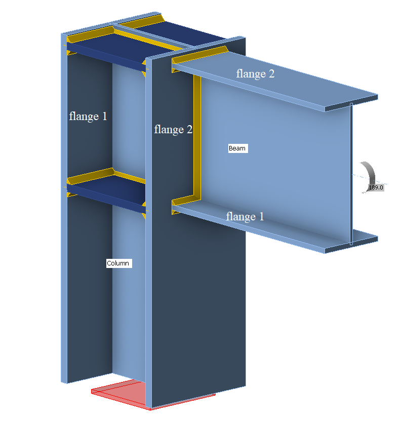
ตาราง 9.1.3 ความต้านทานการออกแบบและส่วนประกอบวิกฤตใน CBFEM และ CM
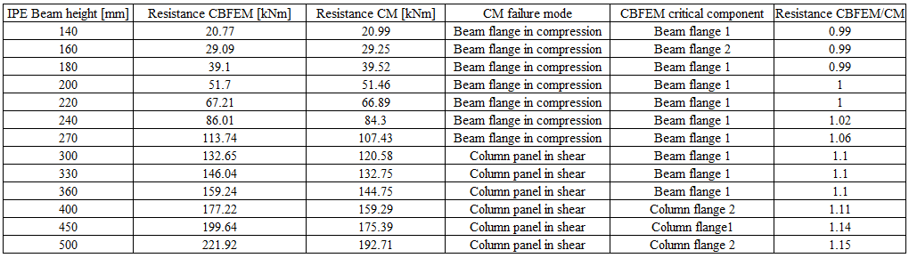
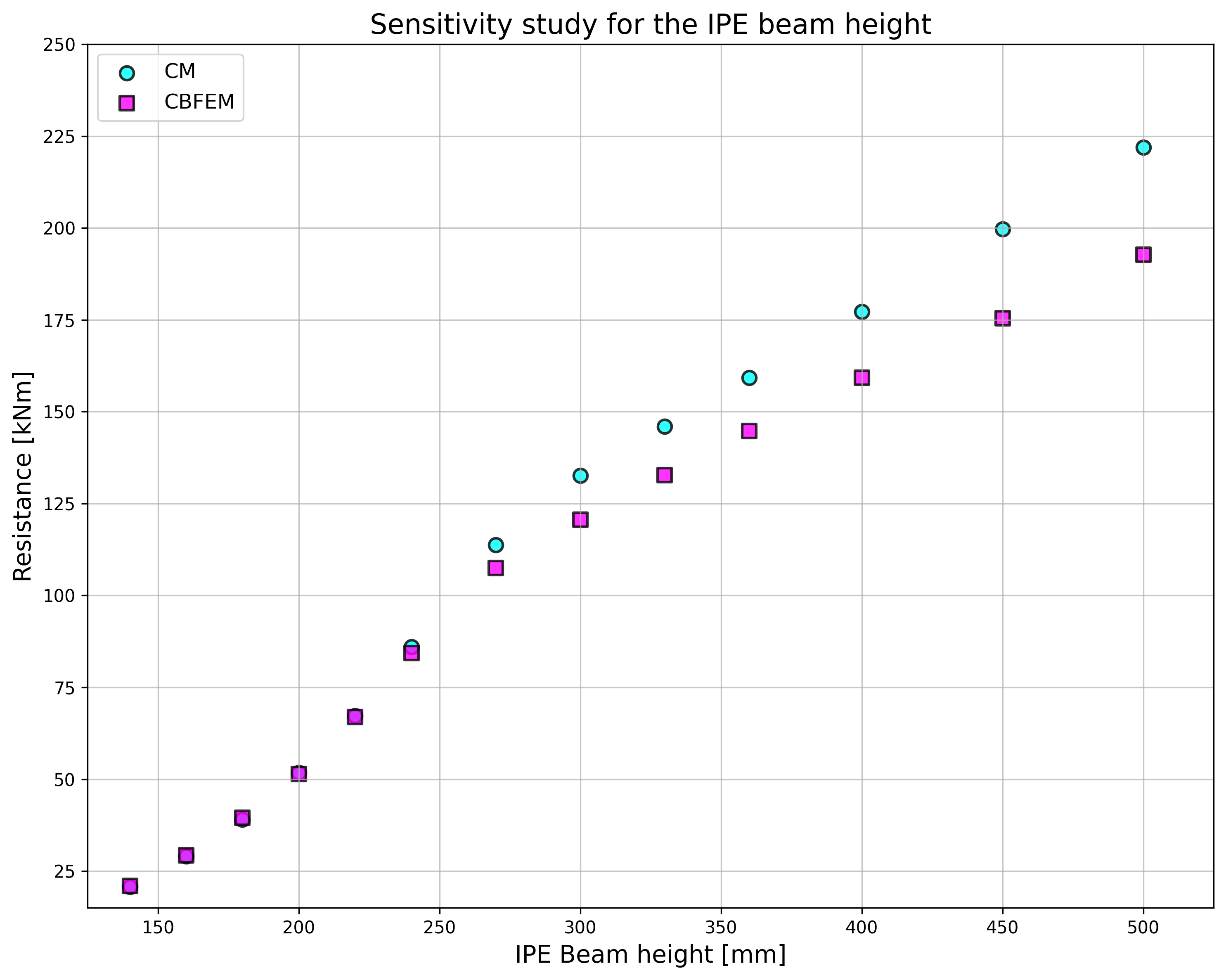
คานหน้าตัดเปิด IPE330 ถูกใช้ในตัวอย่างที่พารามิเตอร์คือหน้าตัดเสา เสาได้รับการเสริมด้วยแผ่นเสริมความแข็งแนวนอนสองแผ่นที่มีความหนา 10 มม. ตรงข้ามกับปีกคาน ความกว้างของแผ่นเสริมความแข็งสอดคล้องกับความกว้างของปีกคาน ความกว้างรวมของแผ่นเสริมความแข็งคือ 160 มม. หน้าตัดเสาถูกเลือกตั้งแต่ HEB 160 ถึง HEB 500 ผลลัพธ์แสดงในตาราง 9.1.4 อิทธิพลของหน้าตัดเสาต่อความต้านทานการออกแบบของการเชื่อมต่อโมเมนต์โครงพอร์ทัลแบบเชื่อมแสดงในรูปที่ 9.1.5
ตาราง 9.1.4 ความต้านทานการออกแบบและส่วนประกอบวิกฤตของการเชื่อมต่อโมเมนต์ใน CBFEM และ CM
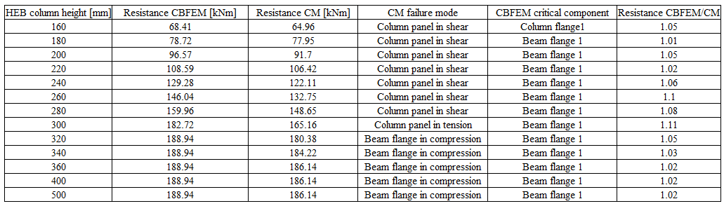
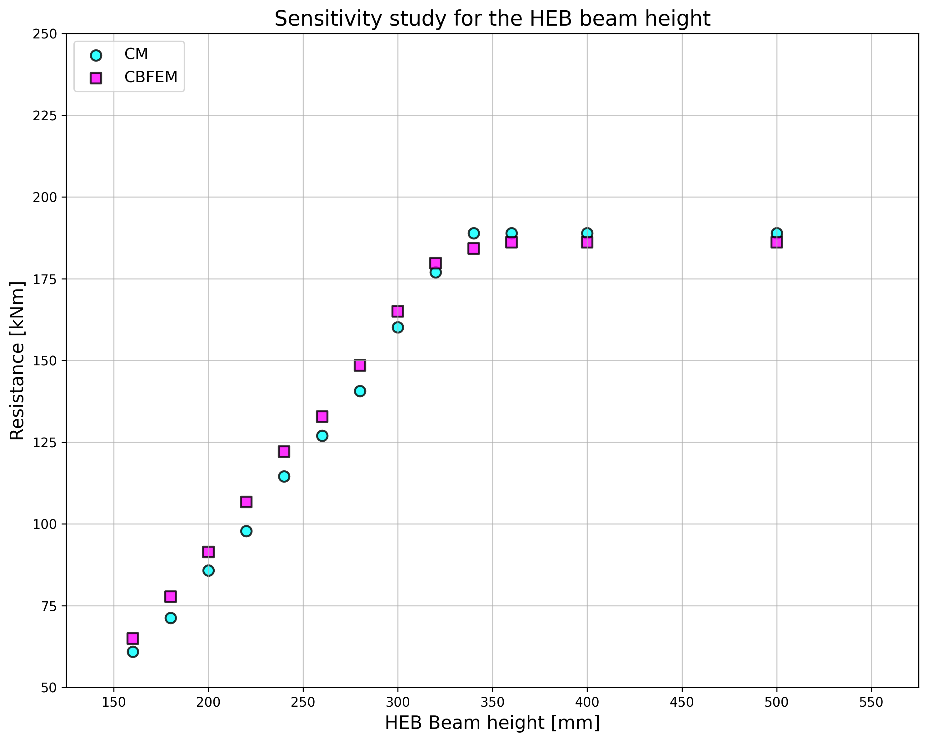
ตัวอย่างที่สามนำเสนอการเชื่อมต่อโมเมนต์โครงพอร์ทัลที่ประกอบด้วยคานหน้าตัดเปิด IPE 330 และเสา HEA 320 พารามิเตอร์คือความหนาของเอวเสา เสาได้รับการเสริมด้วยแผ่นเสริมความแข็งแนวนอนสองแผ่นที่มีความหนา 10 มม. และความกว้าง 160 มม. ความหนาของเอวเสาถูกเลือกตั้งแต่ 4 ถึง 16 มม. ผลลัพธ์สรุปไว้ในตาราง 9.1.5 อิทธิพลของความหนาเอวเสาต่อความต้านทานการออกแบบของการเชื่อมต่อโมเมนต์โครงพอร์ทัลแบบเชื่อมแสดงในรูปที่ 9.1.6
ตาราง 9.1.5 ความต้านทานการออกแบบและส่วนประกอบวิกฤตของการเชื่อมต่อโมเมนต์ใน CBFEM และ CM
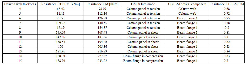
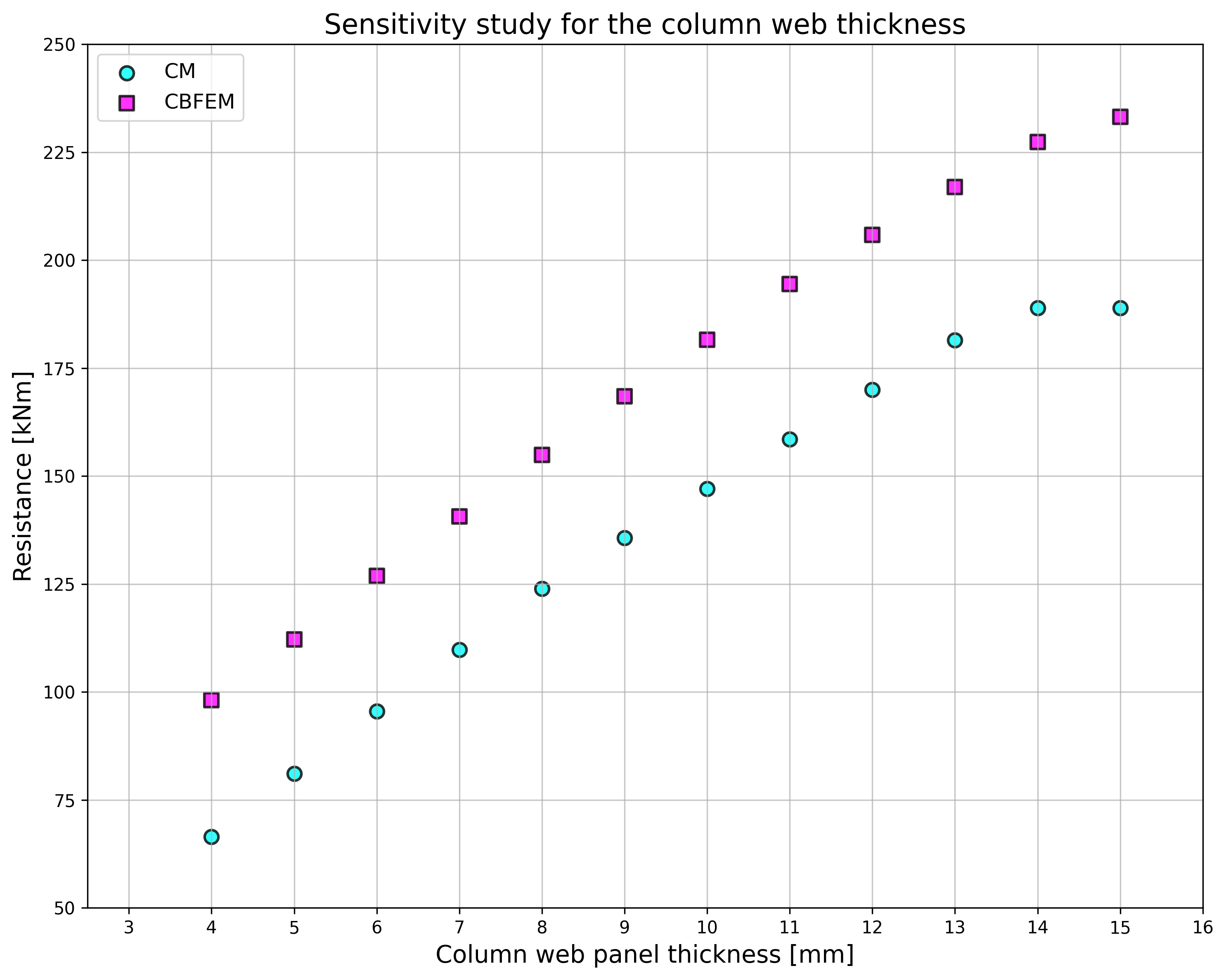
เพื่อแสดงให้เห็นความแม่นยำของแบบจำลอง CBFEM ผลลัพธ์ของการศึกษาพารามิเตอร์ถูกสรุปในแผนภาพที่เปรียบเทียบความต้านทานของ CBFEM และวิธีส่วนประกอบ ดูรูปที่ 9.1.7 ผลลัพธ์แสดงให้เห็นว่าความแตกต่างระหว่างวิธีการคำนวณทั้งสองน้อยกว่า 5% ซึ่งเป็นค่าที่ยอมรับได้โดยทั่วไป การศึกษาที่มีพารามิเตอร์ความหนาเอวเสาให้ความต้านทานที่สูงกว่าสำหรับแบบจำลอง CBFEM เมื่อเปรียบเทียบกับวิธีส่วนประกอบ ความแตกต่างนี้เกิดจากการพิจารณาหน้าตัดแบบเชื่อม การถ่ายแรงเฉือนในวิธีส่วนประกอบพิจารณาเฉพาะในเอวและละเลยการมีส่วนร่วมของปีก
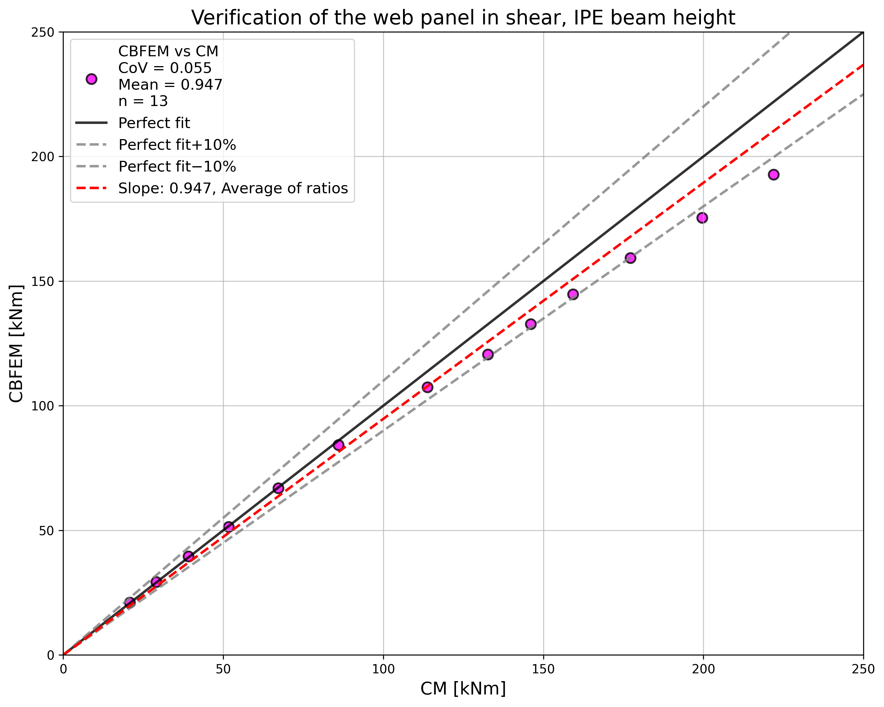
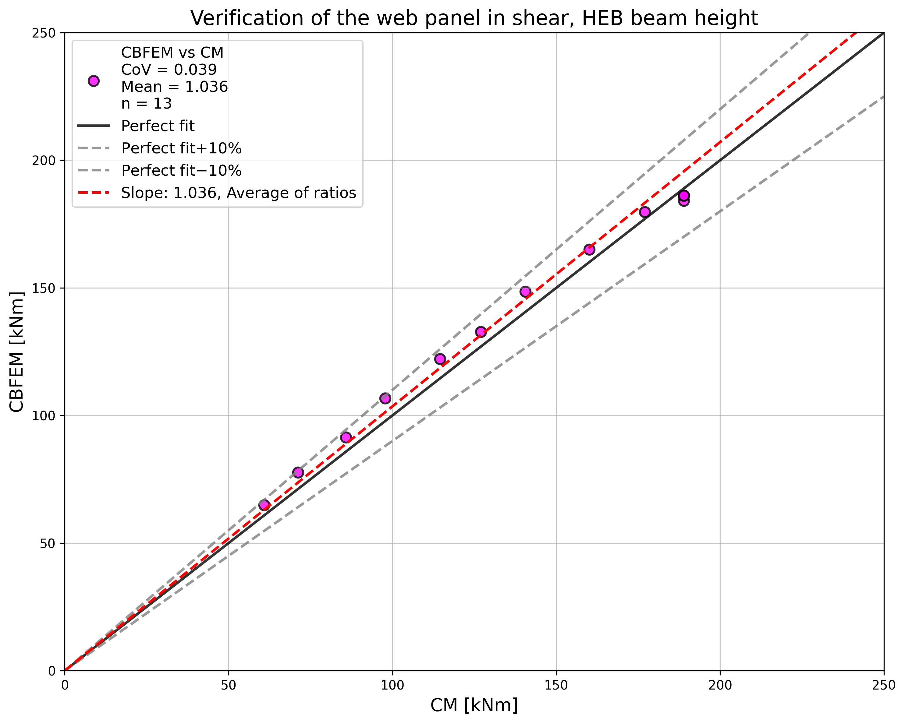
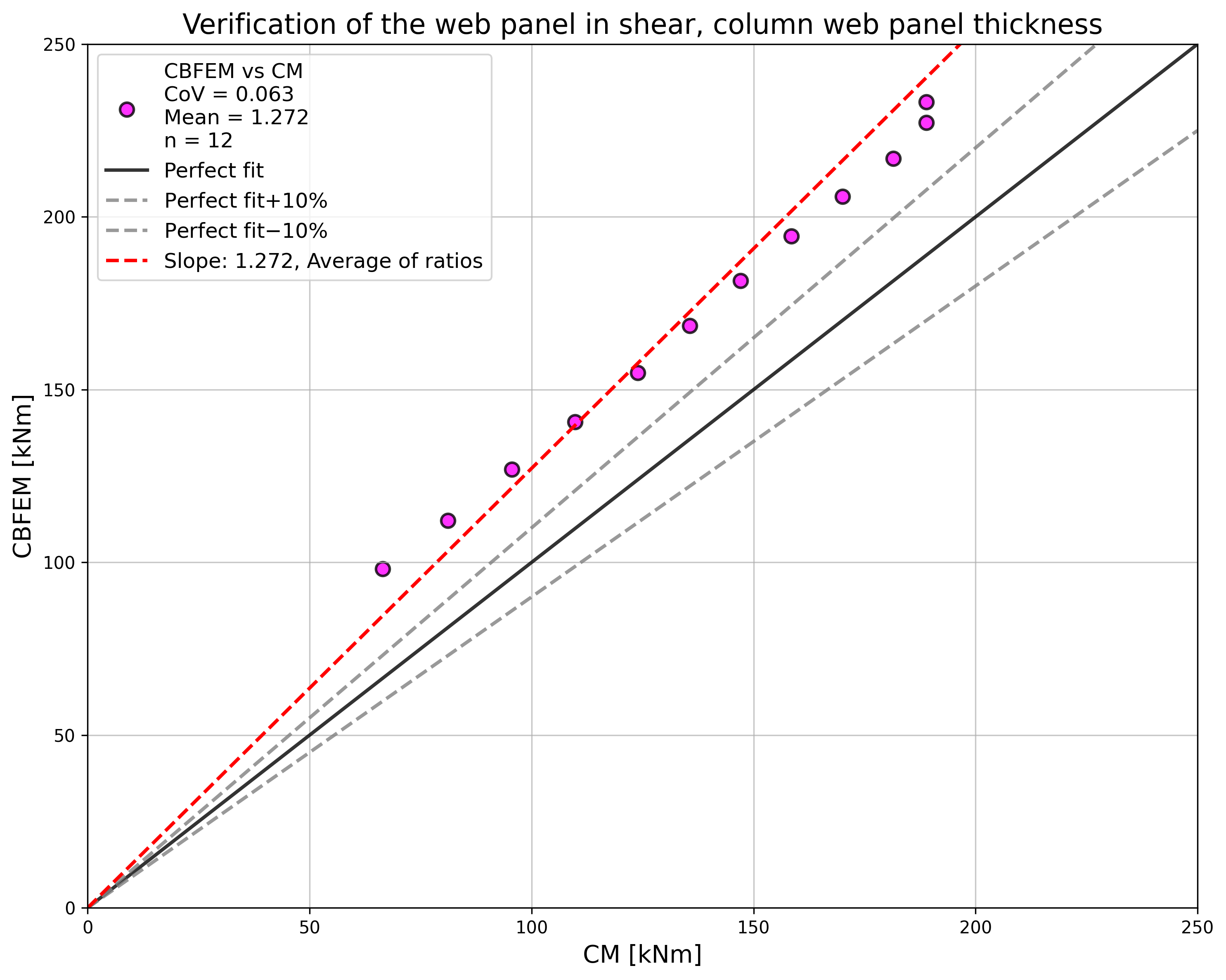
ตัวอย่าง Benchmark
ข้อมูลนำเข้า
เสา
- เหล็ก S235
- HEB260
คาน
- เหล็ก S235
- IPE330
แผ่นเสริมความแข็งเสา
- ความหนา ts = 19 มม.
- ความกว้าง 80 มม.
- ตรงข้ามกับปีกคาน
รอยเชื่อม
- ปีกคาน: ความหนาคอรอยเชื่อมมุม af = 8 มม.
- เอวคาน: ความหนาคอรอยเชื่อมมุม aw = 8 มม.
- รอยเชื่อมชนรอบแผ่นเสริมความแข็ง
ผลลัพธ์
- ความต้านทานการออกแบบในการดัด MRd = 146 kNm
- ส่วนประกอบวิกฤต: ปีกคานที่ 1
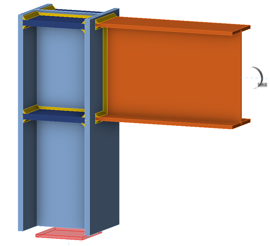
คำอธิบาย
วัตถุประสงค์ของการศึกษานี้คือการตรวจสอบความถูกต้องของการเชื่อมต่อที่มุมหลังคาของโครงพอร์ทัลแบบสลักเกลียว ดังแสดงในรูปที่ 9.2.1 จันทันถูกยึดด้วยสลักเกลียวโดยใช้แผ่นปลายบนปีกเสา เสาได้รับการเสริมด้วยแผ่นเสริมความแข็งแนวนอนสองแผ่นในระดับปีกคาน แผ่นที่รับแรงอัด เช่น แผ่นเสริมความแข็งแนวนอนของเสา แผ่นเว็บในการรับแรงเฉือนหรือแรงอัด และปีกคานที่รับแรงอัด ถูกออกแบบเป็นหน้าตัดชั้น 3 คานแนวนอนมีความยาว 6 ม. รับน้ำหนักบรรทุกแบบกระจายสม่ำเสมอตลอดความยาว
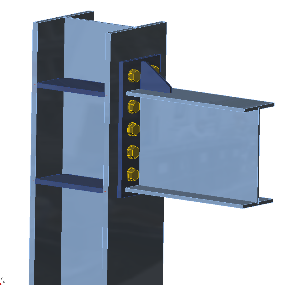
รูปที่ 9.2.1 การเชื่อมต่อที่มุมหลังคาของโครงพอร์ทัลแบบสลักเกลียว
แบบจำลองเชิงวิเคราะห์
มีการตรวจสอบส่วนประกอบแปดชิ้น ได้แก่ รอยเชื่อมมุม แผ่นเว็บในการรับแรงเฉือน แผ่นเว็บเสาในการรับแรงอัดตามขวาง แผ่นเว็บเสาในการรับแรงดึงตามขวาง ปีกคานในการรับแรงอัดและแรงดึง ปีกเสาในการดัด แผ่นปลายในการดัด และสลักเกลียว ส่วนประกอบทั้งหมดได้รับการออกแบบตาม EN 1993-1-8:2005 ค่าการออกแบบของส่วนประกอบขึ้นอยู่กับตำแหน่ง แผ่นเว็บในการรับแรงเฉือนรับค่าการออกแบบบนแกนแนวตั้งของเสา ส่วนประกอบอื่นๆ รับค่าการออกแบบที่ลดลงที่ปีกเสาซึ่งเชื่อมต่อกับคานแนวนอน
รอยเชื่อมมุม
รอยเชื่อมล้อมรอบหน้าตัดทั้งหมดของคาน ความหนาของรอยเชื่อมที่ปีกอาจแตกต่างจากความหนาของรอยเชื่อมที่เว็บ แรงเฉือนแนวตั้งถ่ายผ่านรอยเชื่อมที่เว็บเท่านั้น และพิจารณาการกระจายความเค้นแบบพลาสติก โมเมนต์ดัดถ่ายผ่านรูปทรงรอยเชื่อมทั้งหมด และพิจารณาการกระจายความเค้นแบบยืดหยุ่น มีการพิจารณาความกว้างรอยเชื่อมที่มีประสิทธิผลซึ่งขึ้นอยู่กับความแข็งแนวนอนของเสา (เนื่องจากการดัดของปีกเสาที่ไม่มีแผ่นเสริมความแข็ง) การออกแบบรอยเชื่อมดำเนินการตาม EN 1993-1-8:2005 ข้อ 4.5.3.2(6) การประเมินดำเนินการที่จุดหลักสองจุด ได้แก่ ที่ขอบบนหรือล่างของปีก (ความเค้นดัดสูงสุด) และที่จุดตัดระหว่างปีกและเว็บ (การรวมกันของความเค้นจากแรงเฉือนและโมเมนต์ดัด)
แผ่นเว็บในการรับแรงเฉือน
ความหนาของแผ่นเว็บเสาได้รับการออกแบบให้อยู่ในชั้นที่สามเป็นอย่างมาก ดูใน EN 1993-1-8:2005 ข้อ 6.2.6.1(1) พิจารณาการมีส่วนร่วมสองส่วนต่อความสามารถรับแรง ได้แก่ ความต้านทานของผนังเสาในการรับแรงเฉือน และการมีส่วนร่วมจากพฤติกรรมโครงของปีกเสาและแผ่นเสริมความแข็งแนวนอน ดูใน EN 1993-1-8:2005 ข้อ 6.2.6.1 (6.7 และ 6.8)
แผ่นเว็บเสาในการรับแรงอัดหรือแรงดึงตามขวาง
พิจารณาผลของปฏิกิริยาระหว่างแรงเฉือน ดูใน EN 1993-1-8:2005 ข้อ 6.2.6.2 และตาราง 6.3 พิจารณาอิทธิพลของความเค้นตามยาวในผนังเสา ดูใน EN 1993-1-8:2005 ข้อ 6.2.6.2(2) แผ่นเสริมความแข็งแนวนอนป้องกันการโก่งเดาะและรวมอยู่ในความสามารถรับแรงของส่วนประกอบนี้ด้วยพื้นที่ที่มีประสิทธิผล
ปีกคานในการรับแรงอัด
คานแนวนอนได้รับการออกแบบให้อยู่ในชั้นที่สามเป็นอย่างมาก
ปีกเสาหรือแผ่นปลายในการดัด
พิจารณาความยาวที่มีประสิทธิผลสำหรับการวิบัติแบบวงกลมและไม่ใช่วงกลมตาม EN 1993-1-8:2005 ข้อ 6.2.6 พิจารณาสามรูปแบบการพังทลายตาม EN 1993-1-8:2005 ข้อ 6.2.4.1
สลักเกลียว
สลักเกลียวได้รับการออกแบบตาม EN 1993-1-8:2005 ข้อ 3.6.1 ความต้านทานการออกแบบพิจารณาความต้านทานการเฉือนทะลุและการขาดของสลักเกลียว
แบบจำลองการออกแบบเชิงตัวเลข
T-stub ถูกจำลองด้วยองค์ประกอบเปลือกแบบ 4 โหนด ตามที่อธิบายในบทที่ 3 และสรุปเพิ่มเติม แต่ละ Node มี 6 องศาอิสระ การเสียรูปของชิ้นส่วนประกอบด้วยการมีส่วนร่วมของเมมเบรนและการดัด สถานะวัสดุแบบยืดหยุ่น-พลาสติกไม่เชิงเส้นได้รับการตรวจสอบในแต่ละชั้นของจุดอินทิเกรชัน การประเมินอ้างอิงจากความเครียดสูงสุดตาม EN 1993-1-5:2006 ที่ค่า 5 % สลักเกลียวแบ่งออกเป็นสามส่วนประกอบย่อย ส่วนแรกคือก้านสลักเกลียว ซึ่งจำลองเป็น Spring ไม่เชิงเส้นและรับแรงดึงเท่านั้น ส่วนประกอบย่อยที่สองถ่ายแรงดึงไปยังปีก ส่วนประกอบย่อยที่สามแก้ปัญหาการถ่ายแรงเฉือน
พฤติกรรมโดยรวม
มีการเปรียบเทียบพฤติกรรมโดยรวมของจุดต่อ ซึ่งอธิบายด้วยไดอะแกรมโมเมนต์-การหมุนสำหรับทั้งสองวิธีการออกแบบที่กล่าวถึงข้างต้น โดยให้ความสนใจกับลักษณะสำคัญของไดอะแกรมโมเมนต์-การหมุน ได้แก่ ความแข็งเริ่มต้น ความต้านทานการออกแบบ และความสามารถในการเสียรูป คาน IPE 330 เชื่อมต่อกับเสา HEB 300 โดยใช้แผ่นปลายแบบขยายพร้อมสลักเกลียว M24 8.8 จำนวน 5 แถว ผลลัพธ์ของทั้งสองวิธีการออกแบบแสดงในกราฟในรูปที่ 9.2.2 และในตาราง 9.2.1 โดยทั่วไป CM ให้ความแข็งเริ่มต้นสูงกว่าเมื่อเปรียบเทียบกับ CBFEM CBFEM ให้ความต้านทานการออกแบบสูงกว่า CM เล็กน้อยในทุกกรณี ดังแสดงในบทที่ 9.2.5 ความแตกต่างอยู่ที่ ไม่เกิน 10% นอกจากนี้ยังมีการเปรียบเทียบความสามารถในการเสียรูป ความสามารถในการเสียรูปคำนวณตาม (Beg et al. 2004) เนื่องจาก EC3 ให้พื้นฐานที่จำกัดสำหรับความสามารถในการเสียรูปของจุดต่อแผ่นปลาย
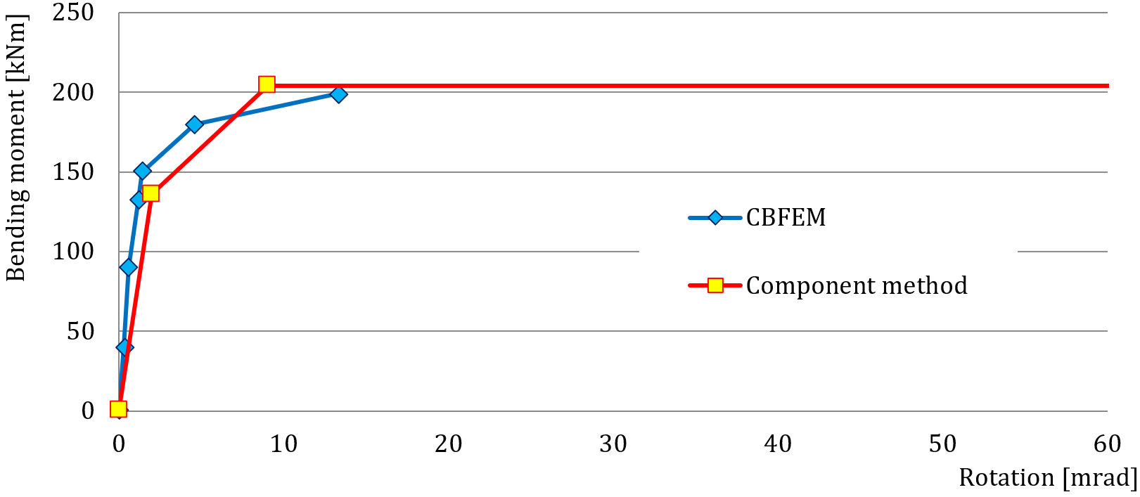
รูปที่ 9.2.2 ไดอะแกรมโมเมนต์-การหมุน
ตาราง 9.2.1 ภาพรวมพฤติกรรมโดยรวม
| CM | CBFEM | CM/CBFEM | ||
| ความแข็งเริ่มต้น | [kNm/rad] | 67400 | 112000 | 0,60 |
| ความต้านทานการออกแบบ | [kNm] | 204 | 199 | 0,98 |
| ความสามารถในการเสียรูป | [mrad] | 242 | 47 | 5,14 |
การตรวจสอบความต้านทาน
ความต้านทานการออกแบบที่คำนวณโดย CBFEM ถูกเปรียบเทียบกับผลลัพธ์ของวิธีส่วนประกอบในขั้นตอนถัดไป การเปรียบเทียบมุ่งเน้นที่ความต้านทานและส่วนประกอบวิกฤต การศึกษาดำเนินการสำหรับพารามิเตอร์หน้าตัดเสา คาน IPE 330 เชื่อมต่อกับเสาโดยใช้แผ่นปลายแบบขยายพร้อมสลักเกลียว 5 แถว ใช้สลักเกลียว M24 8.8 ขนาดของแผ่นปลาย P15 พร้อมระยะขอบและระยะห่างของสลักเกลียวในหน่วยมิลลิเมตร ได้แก่ ความสูง 450 (50-103-75-75-75-73) และความกว้าง 200 (50-100-50) ขอบนอกของปีกบนอยู่ห่างจากขอบแผ่นปลาย 91 มม. ปีกคานเชื่อมต่อกับแผ่นปลายด้วยรอยเชื่อมที่มีความหนาคอ 8 มม. เว็บคานเชื่อมต่อด้วยความหนาคอรอยเชื่อม 5 มม. เสาได้รับการเสริมด้วยแผ่นเสริมความแข็งแนวนอนตรงข้ามกับปีกคาน แผ่นเสริมความแข็งมีความหนา 15 มม. และความกว้างสอดคล้องกับความกว้างเสา ความหนาของแผ่นเสริมความแข็งแผ่นปลายคือ 10 มม. และความกว้างคือ 90 มม. ผลลัพธ์แสดงในตาราง 9.2.2 และรูปที่ 9.2.3
ตาราง 9.2.2 ความต้านทานการออกแบบสำหรับพารามิเตอร์ – หน้าตัดเสา
| หน้าตัดเสา | CM | CBFEM | CM/ CBFEM | ||
| ความต้านทาน | ส่วนประกอบ | ความต้านทาน | ส่วนประกอบ | ||
| [kNm] | [kNm] | ||||
| HEB 200 | 107 | แผ่นเว็บเสาในการรับแรงเฉือน | 106 | แผ่นเว็บเสาในการรับแรงเฉือน | 1,01 |
| HEB 220 | 121 | แผ่นเว็บเสาในการรับแรงเฉือน | 136 | แผ่นเว็บเสาในการรับแรงเฉือน | 0,89 |
| HEB 240 | 143 | แผ่นเว็บเสาในการรับแรงเฉือน | 155 | แผ่นเว็บเสาในการรับแรงเฉือน | 0,92 |
| HEB 260 | 160 | แผ่นเว็บเสาในการรับแรงเฉือน | 169 | แผ่นเว็บเสาในการรับแรงเฉือน | 0,95 |
| HEB 280 | 176 | แผ่นเว็บเสาในการรับแรงเฉือน | 187 | แผ่นเว็บเสาในการรับแรงเฉือน | 0,94 |
| HEB 300 | 204 | แผ่นเว็บเสาในการรับแรงเฉือน | 199 | ปีกคานในการรับแรงดึง/แรงอัด | 0,98 |
| HEB 320 | 222 | แผ่นเว็บเสาในการรับแรงเฉือน | 225 | ปีกคานในการรับแรงดึง/แรงอัด | 0,99 |
| HEB 340 | 226 | ปีกคานในการรับแรงดึง/แรงอัด | 242 | ปีกคานในการรับแรงดึง/แรงอัด | 0,93 |
| HEB 360 | 229 | ปีกคานในการรับแรงดึง/แรงอัด | 239 | ปีกคานในการรับแรงดึง/แรงอัด | 0,96 |
| HEB 400 | 234 | ปีกคานในการรับแรงดึง/แรงอัด | 253 | ปีกคานในการรับแรงดึง/แรงอัด | 0,92 |
| HEB 450 | 241 | ปีกคานในการรับแรงดึง/แรงอัด | 260 | ปีกคานในการรับแรงดึง/แรงอัด | 0,93 |
| HEB 500 | 248 | ปีกคานในการรับแรงดึง/แรงอัด | 268 | ปีกคานในการรับแรงดึง/แรงอัด | 0,93 |
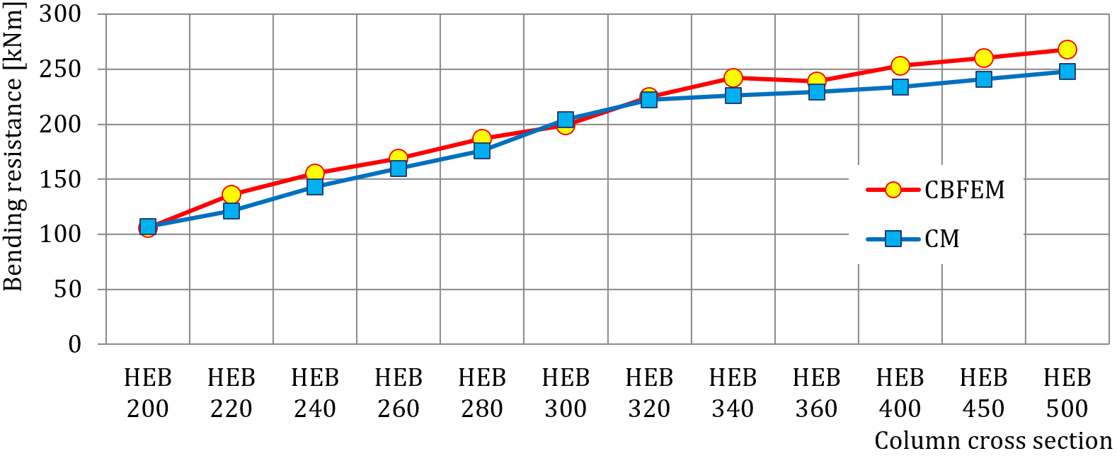
รูปที่ 9.2.3 ความต้านทานการออกแบบขึ้นอยู่กับหน้าตัดเสา
เพื่อแสดงความแม่นยำของแบบจำลอง CBFEM ผลลัพธ์ของการศึกษาพารามิเตอร์ถูกสรุปในกราฟที่เปรียบเทียบความต้านทานที่คาดการณ์โดย CBFEM และโดย CM ดูรูปที่ 9.2.4 ผลลัพธ์แสดงให้เห็นว่า CBFEM ให้ความต้านทานการออกแบบสูงกว่า CM เล็กน้อยในเกือบทุกกรณี ความแตกต่างระหว่างทั้งสองวิธีอยู่ที่ไม่เกิน 10%
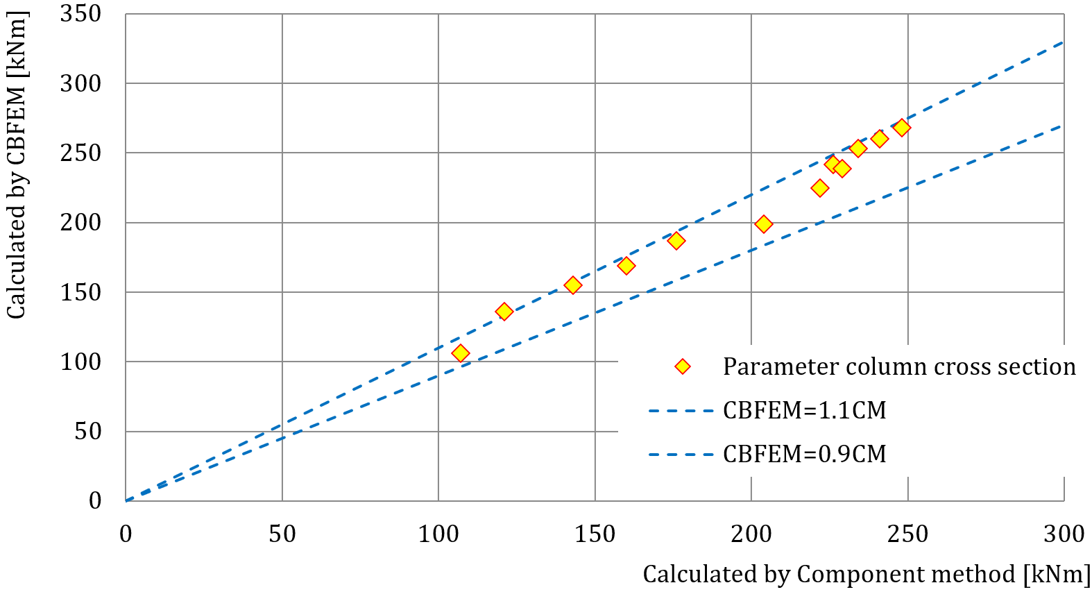
รูปที่ 9.2.4 การตรวจสอบความถูกต้องของ CBFEM เทียบกับ CM
ตัวอย่าง Benchmark
ข้อมูลนำเข้า
- เหล็ก S235
- คาน IPE 330
- เสา HEB 300
- ความสูงแผ่นปลาย hp = 450 (50-103-75-75-75-73) มม.
- ความกว้างแผ่นปลาย bp = 200 (50-100-50) มม.
- แผ่นปลาย P15
- แผ่นเสริมความแข็งเสาหนา 15 มม. และกว้าง 300 มม.
- แผ่นเสริมความแข็งแผ่นปลายหนา 10 มม. กว้างและลึก 90 มม. มุมลบคม 20 มม.
- ความหนาคอรอยเชื่อมปีก af = 8 มม.
- ความหนาคอรอยเชื่อมเว็บและแผ่นเสริมความแข็งแผ่นปลาย aw = 5 มม.
- สลักเกลียว M24 8.8
ผลลัพธ์
- ความต้านทานการออกแบบในการดัด MRd = 206 kNm
- แรงเฉือนแนวตั้งที่สอดคล้องกัน VEd= –206 kN
- รูปแบบการพังทลาย: การครากของแผ่นเสริมความแข็งคานที่ปีกบน
- อัตราการใช้งานของสลักเกลียว 90,2 %
- อัตราการใช้งานของรอยเชื่อม 99,0 %
การทำนายความแข็งเกร็ง
คำอธิบาย
การทำนายความแข็งแกร่งต่อการหมุนได้รับการอธิบายบนจุดต่อโมเมนต์แบบเชื่อมที่ชายคา คานเหล็กหน้าตัดเปิด HEB และ IPE ที่เชื่อมต่อกันได้รับการศึกษา และพฤติกรรมของจุดต่อได้รับการอธิบายบนแผนภาพโมเมนต์-การหมุน ผลลัพธ์ของแบบจำลองเชิงวิเคราะห์โดยวิธีส่วนประกอบ (CM) ได้รับการเปรียบเทียบกับผลลัพธ์เชิงตัวเลขที่ได้จากวิธี Component-Based Finite Element (CBFEM) และมีกรณีเปรียบเทียบมาตรฐานให้ใช้งาน
แบบจำลองเชิงวิเคราะห์
ความแข็งแกร่งต่อการหมุนของจุดต่อควรได้รับการกำหนดจากการเสียรูปของส่วนประกอบพื้นฐาน ซึ่งแสดงด้วยสัมประสิทธิ์ความแข็งแกร่ง ki ความแข็งแกร่งต่อการหมุนของจุดต่อ Sj ได้จาก:
โดยที่:
- ki คือสัมประสิทธิ์ความแข็งแกร่งสำหรับส่วนประกอบจุดต่อ i;
- z คือแขนโมเมนต์ ดู 6.2.7;
- μ คืออัตราส่วนความแข็งแกร่ง ดู 6.3.1.
ส่วนประกอบของจุดต่อที่นำมาพิจารณาในตัวอย่างนี้ได้แก่ แผ่นเอวเสาในแรงเฉือน k1 แผ่นเอวเสาในแรงอัด k2, และแผ่นเอวเสาในแรงดึง k3 สัมประสิทธิ์ความแข็งแกร่งได้รับการกำหนดในตาราง 6.11 ใน EN 1993-1-8:2005 ความแข็งแกร่งเริ่มต้น Sj,ini ได้รับสำหรับโมเมนต์ Mj,Ed ≤ 2/3 Mj,Rd.
โดยที่
— ความแข็งแกร่งต่อการหมุนของจุดต่อ
= 2.7 — EN 1993-1-8 ตาราง 6.8
คานหน้าตัดเปิด IPE 400 ถูกเชื่อมเข้ากับเสา HEB 300 ในตัวอย่าง ปีกคานเชื่อมต่อกับปีกเสาด้วยรอยเชื่อมที่มีความหนาคอ 9 มม. แผ่นเอวคานเชื่อมต่อด้วยรอยเชื่อมที่มีความหนาคอ 5 มม. การกระจายความเค้นแบบพลาสติกได้รับการพิจารณาในรอยเชื่อม วัสดุของคานและเสาเป็น S235 ความต้านทานการออกแบบถูกจำกัดโดยส่วนประกอบแผ่นเอวเสาในแรงเฉือนและแผ่นเอวเสาในแรงอัดตามขวาง ค่าสัมประสิทธิ์ความแข็งแกร่งของส่วนประกอบพื้นฐาน ความแข็งแกร่งเริ่มต้น ความแข็งแกร่งตามความต้านทานการออกแบบ และการหมุนของคานได้รับการสรุปในตาราง 10.1.1
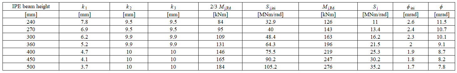
แบบจำลองเชิงตัวเลข
ข้อมูลโดยละเอียดเกี่ยวกับการทำนายความแข็งแกร่งใน CBFEM สามารถพบได้ในบทที่ 3.9 จุดต่อโมเมนต์แบบเชื่อมที่ชายคาเดียวกันได้รับการจำลอง และผลลัพธ์แสดงในตาราง 10.1.2 ความต้านทานการออกแบบถูกบรรลุโดยความเครียดพลาสติก 5% ในส่วนประกอบแผ่นเอวเสาในแรงดึง การวิเคราะห์ CBFEM ช่วยให้สามารถคำนวณความแข็งแกร่งต่อการหมุนได้ในทุกขั้นตอนของการรับน้ำหนัก
ภาพรวมการทดลอง
เพื่อวัตถุประสงค์ในการเปรียบเทียบ หน้าตัดเสาถูกกำหนดเป็น HEB300 และหน้าตัดคานมีการเปลี่ยนแปลง วัสดุทั้งหมดที่ใช้เป็น S235
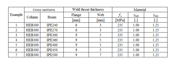
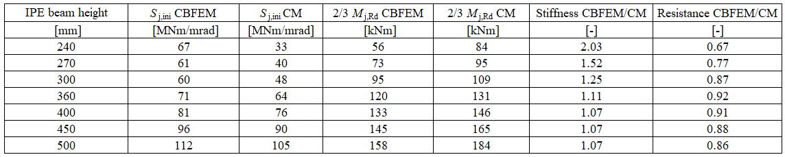
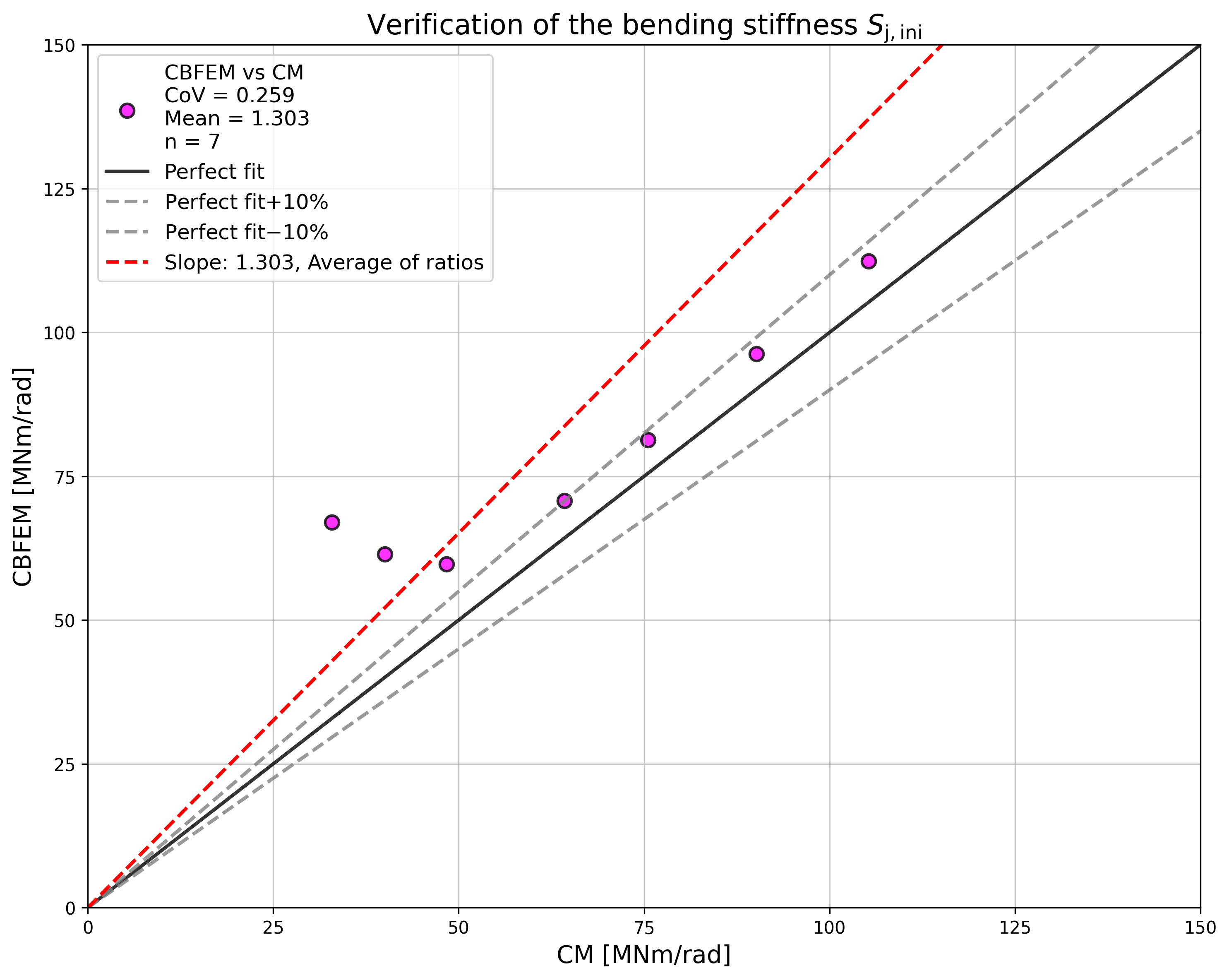
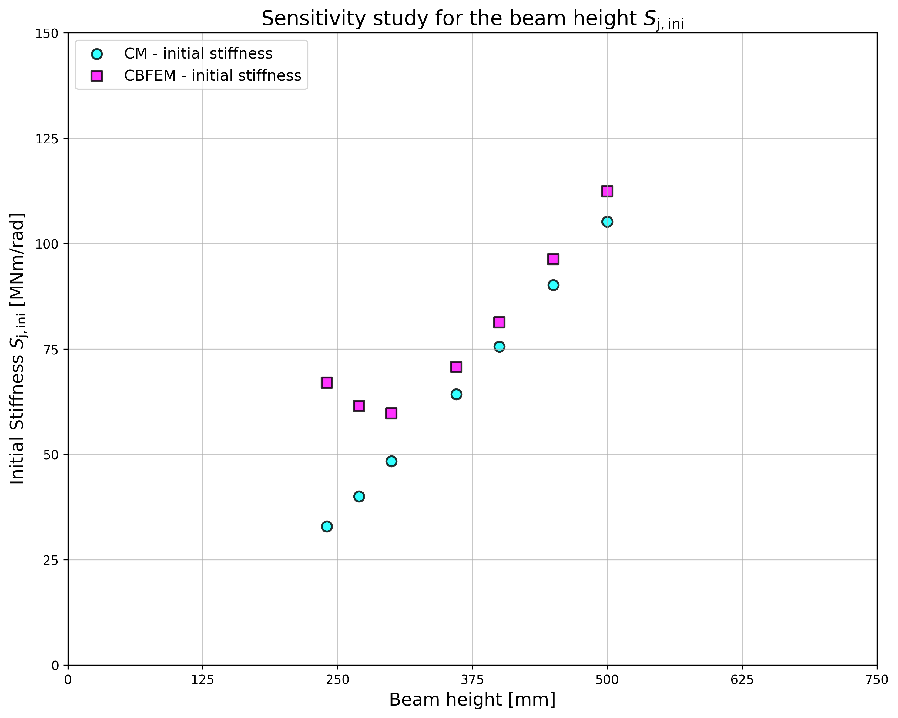
การตรวจสอบความแข็งแกร่ง
ความแข็งแกร่งต่อการหมุนที่คำนวณโดย CBFEM ได้รับการเปรียบเทียบกับ CM การเปรียบเทียบแสดงให้เห็นความสอดคล้องที่ดีในความแข็งแกร่งเริ่มต้นและความสอดคล้องของพฤติกรรมจุดต่อ ความแข็งแกร่งที่คำนวณได้จาก CBFEM และ CM ได้รับการสรุปในตาราง 10.1.3
การเปรียบเทียบพฤติกรรมโดยรวมของจุดต่อโมเมนต์แบบเชื่อมที่ชายคาซึ่งอธิบายด้วยแผนภาพโมเมนต์-การหมุนได้รับการจัดทำขึ้น จุดต่อได้รับการวิเคราะห์ และความแข็งแกร่งของคานที่เชื่อมต่อได้รับการคำนวณ ลักษณะสำคัญคือความแข็งแกร่งเริ่มต้นที่คำนวณที่ 2/3Mj,Rd โดยที่ Mj,Rd คือความต้านทานโมเมนต์การออกแบบของจุดต่อ แผนภาพโมเมนต์-การหมุนแสดงในรูปที่ 10.1.1
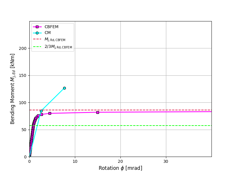
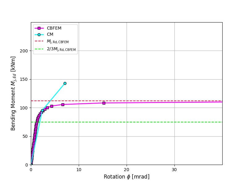
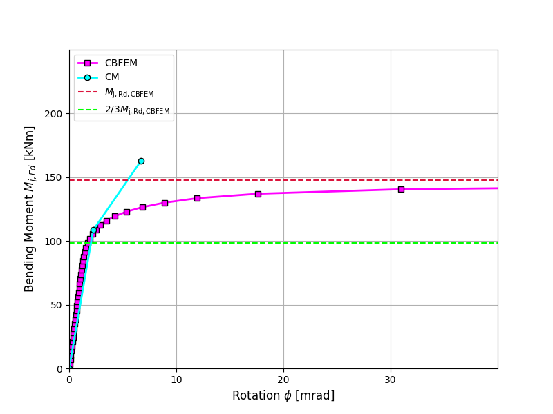
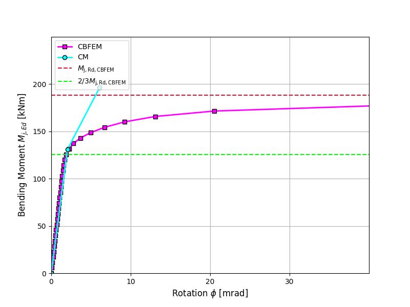
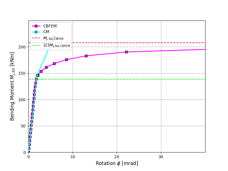
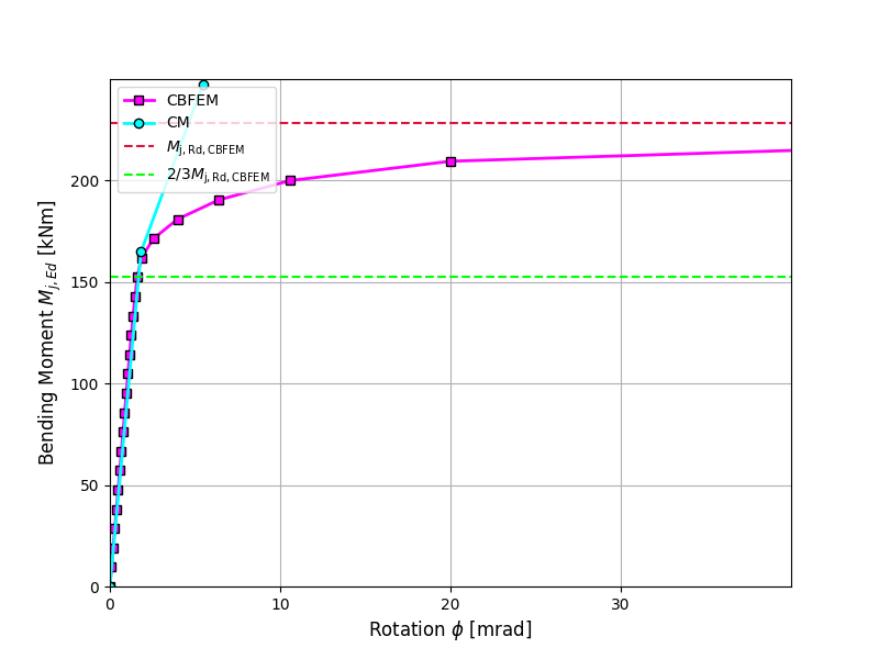
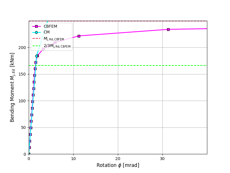
กรณีเปรียบเทียบมาตรฐาน
ข้อมูลนำเข้า
คานและเสา
- เหล็ก S235
- เสา HEB 300
- คาน IPE 400
- ความหนาคอรอยเชื่อมปีก af = 9 มม.
- ความหนาคอรอยเชื่อมแผ่นเอว aw = 5 มม.
- ระยะออฟเซ็ตเสา s = 150 มม.
- รอยเชื่อมตะเข็บคู่
ผลลัพธ์
- ความต้านทานการออกแบบ
- แรงกระทำ
- ความแข็งแกร่งต่อการหมุนแบบ Secant
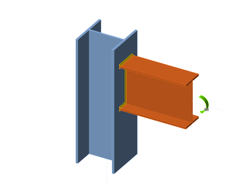
10.2.1 คำอธิบาย
การทำนายความแข็งแกร่งในการหมุนได้รับการตรวจสอบบนจุดต่อโมเมนต์ที่ขอบหลังคาแบบสลักเกลียว จุดต่อสลักเกลียวของหน้าตัดเปิดเสา HEB และคาน IPE ได้รับการศึกษา และพฤติกรรมของจุดต่อถูกอธิบายด้วยแผนภาพโมเมนต์-การหมุน ผลลัพธ์ของแบบจำลองเชิงวิเคราะห์โดยวิธี Component-Based Finite Element (CBFEM) ถูกเปรียบเทียบกับวิธีส่วนประกอบ (CM) ผลลัพธ์เชิงตัวเลขในรูปแบบ benchmark case มีให้ใช้งาน
10.2.2 แบบจำลองเชิงวิเคราะห์
ความแข็งแกร่งในการหมุนของจุดต่อควรถูกกำหนดจากการเสียรูปของส่วนประกอบพื้นฐาน ซึ่งแทนด้วยสัมประสิทธิ์ความแข็งแกร่ง ki ความแข็งแกร่งในการหมุนของจุดต่อ Sj ได้จาก:
โดยที่
— สัมประสิทธิ์ความแข็งแกร่งสำหรับส่วนประกอบจุดต่อ i;
— แขนคาน ดู 6.2.7;
— อัตราส่วนความแข็งแกร่ง ดู 6.3.1
ส่วนประกอบของจุดต่อที่นำมาพิจารณาในตัวอย่างนี้ได้แก่ แผ่นเว็บเสาในแรงเฉือน k1 ซึ่งมีค่าเท่ากับอนันต์สำหรับเสาที่มีแผ่นเสริมความแข็ง และสัมประสิทธิ์ความแข็งแกร่งสมมูลเดี่ยว keq สำหรับจุดต่อแผ่นปลายที่มีแถวสลักเกลียวรับแรงดึงสองแถวขึ้นไป
โดยที่
— ระยะจากแถวสลักเกลียวถึงปีกล่างของคาน ดู Drawing 10.2.1
— สัมประสิทธิ์ความแข็งแกร่งสำหรับส่วนประกอบจุดต่อ i
— แขนคานสมมูล
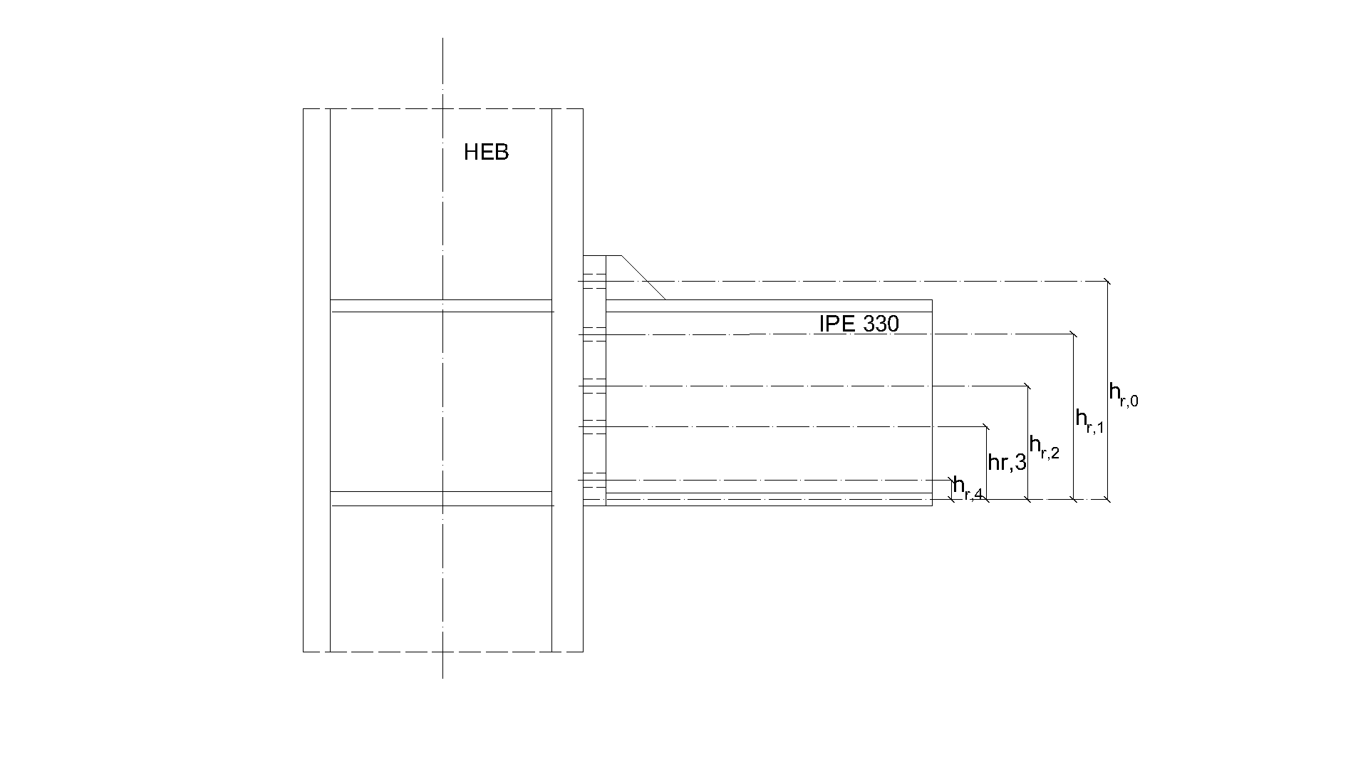
ในตัวอย่างนี้ คานหน้าตัดเปิด IPE 330 ถูกเชื่อมต่อด้วยแผ่นปลายแบบสลักเกลียวกับเสา HEB 200 ความหนาของแผ่นปลายคือ 15 มม. ชนิดสลักเกลียวคือ M24 8.8 และการประกอบแสดงในรูป 10.2.1 ตัวอย่างอื่นมีหน้าตัดเสาที่แตกต่างกัน แผ่นเสริมความแข็งอยู่ภายในเสาตรงข้ามกับปีกคานโดยมีความหนา 15 มม. ปีกคานเชื่อมต่อกับแผ่นปลายด้วยรอยเชื่อมที่มีความหนาคอ 8 มม. เว็บคานเชื่อมต่อด้วยความหนาคอรอยเชื่อม 5 มม. มีการนำพลาสติกซิตี้มาใช้ในรอยเชื่อม วัสดุของคาน เสา และแผ่นปลายเป็น S235 จุดต่อรับแรงดัด ความต้านทานการออกแบบถูกจำกัดโดยส่วนประกอบแผ่นเว็บเสาในแรงเฉือน สัมประสิทธิ์ความแข็งแกร่งของส่วนประกอบพื้นฐาน ความแข็งแกร่งเริ่มต้น ความแข็งแกร่งตามความต้านทานการออกแบบ และการหมุนของคานถูกสรุปไว้ใน Tab. 10.2.1 จุดต่อที่มีความสูงเสาต่ำกว่า 260 มม. มีรูปแบบการวิบัติของแผ่นเว็บในแรงเฉือน ส่วนจุดต่ออื่นมีการวิบัติที่ปีกคานในแรงดึง ดังนั้นความต้านทานการดัดจึงเท่ากัน
Tab. 10.2.1 ผลลัพธ์ของแบบจำลองเชิงวิเคราะห์ (วิธีส่วนประกอบ)
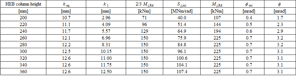
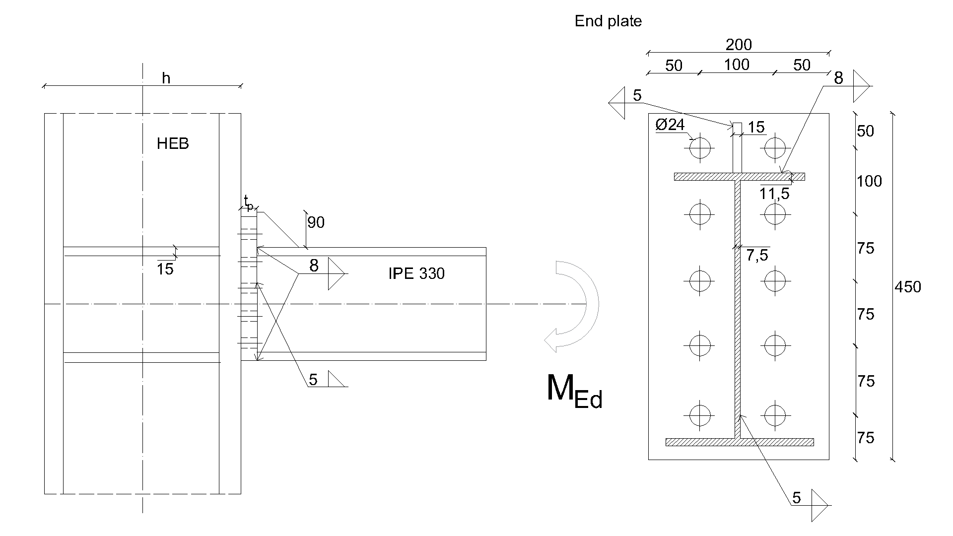
10.2.3 การตรวจสอบความแข็งแกร่ง
ข้อมูลโดยละเอียดเกี่ยวกับการทำนายความแข็งแกร่งใน CBFEM สามารถพบได้ในบทที่ 3.9 การวิเคราะห์ด้วย CBFEM ช่วยให้สามารถคำนวณความแข็งแกร่งในการหมุนแบบ secant ได้ในทุกขั้นตอนของการรับแรง ความต้านทานการออกแบบถูกบรรลุเมื่อความเครียดพลาสติก 5% ในส่วนประกอบแผ่นเว็บเสาในแรงเฉือน ความแข็งแกร่งในการหมุนที่คำนวณโดย CBFEM เปรียบเทียบกับ CM การเปรียบเทียบแสดงให้เห็นความสอดคล้องที่ดีในความแข็งแกร่งเริ่มต้นและความสอดคล้องของพฤติกรรมจุดต่อ ความแข็งแกร่งที่คำนวณจาก CBFEM และ CM ถูกสรุปไว้ในรูป 10.2.2
Tab. 10.2.2 การตรวจสอบ CBFEM กับ CM
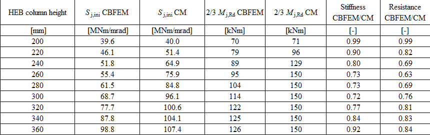
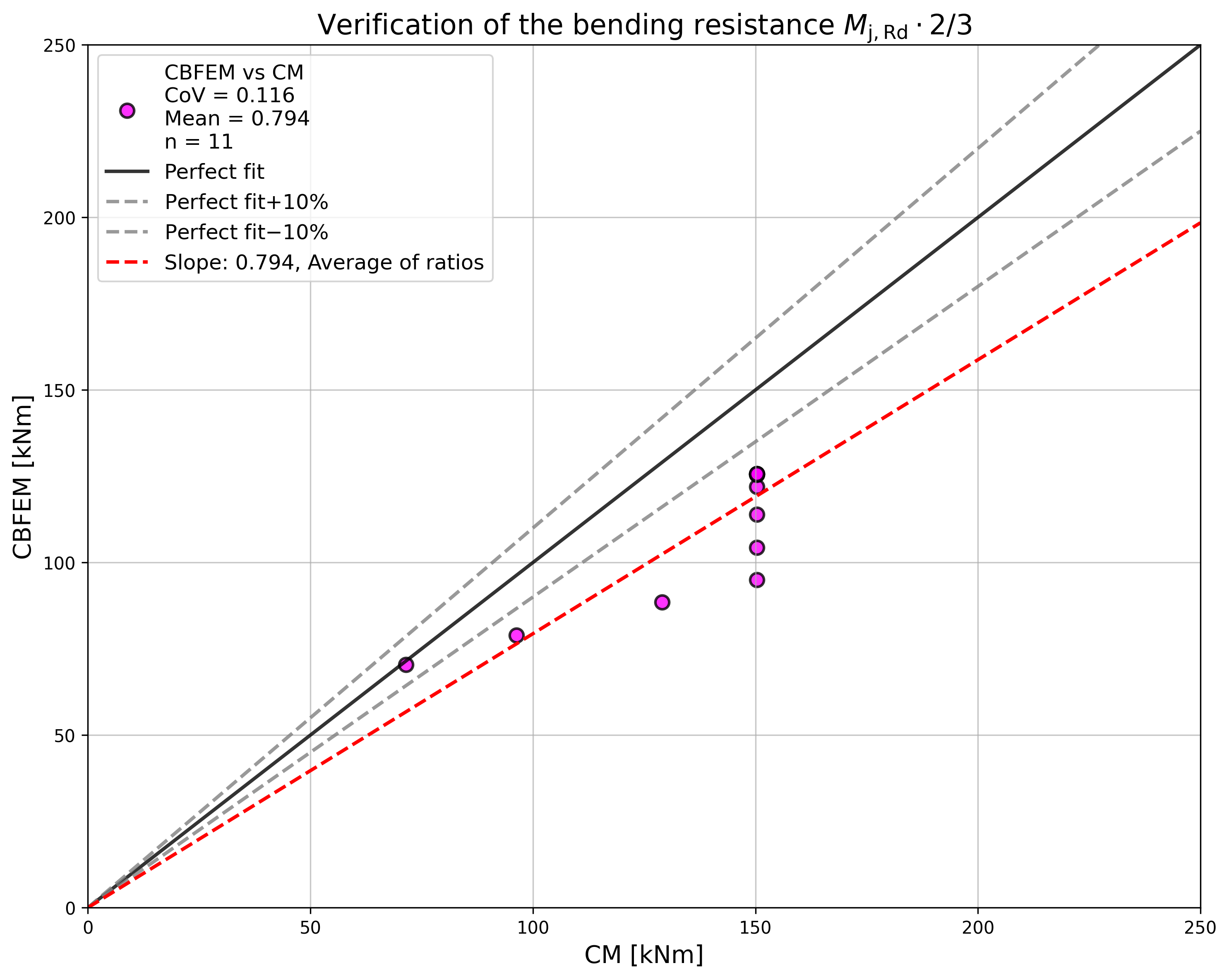
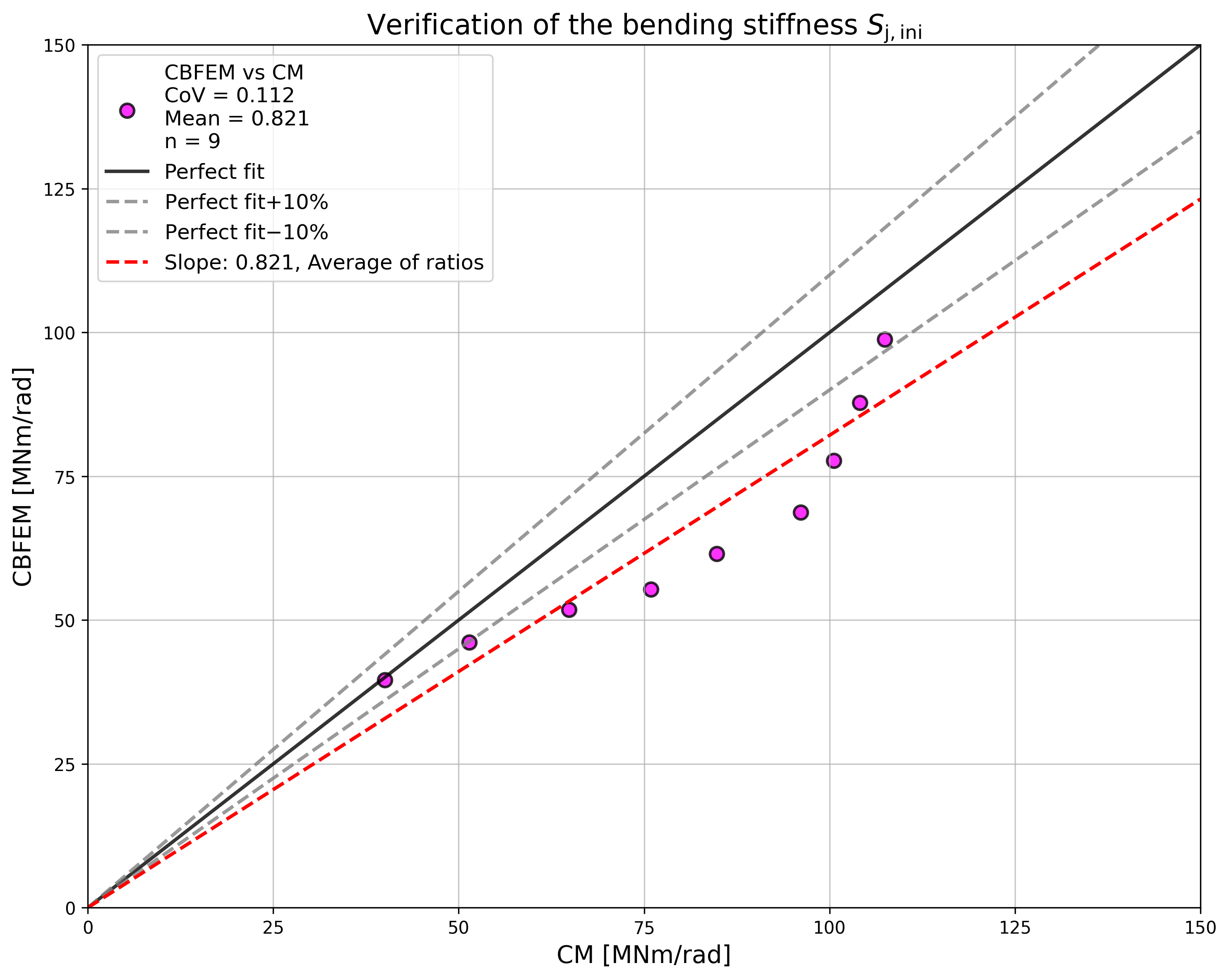
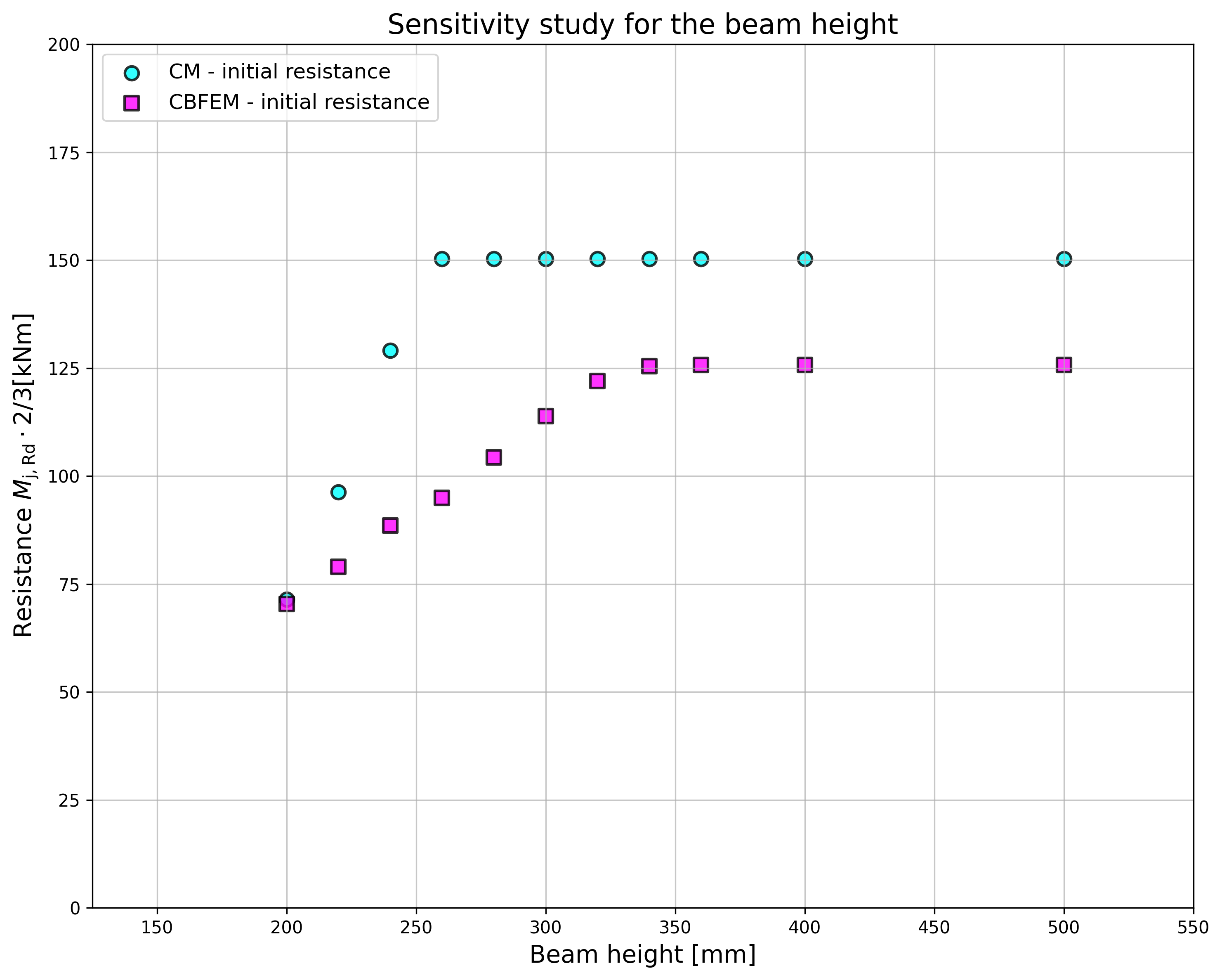
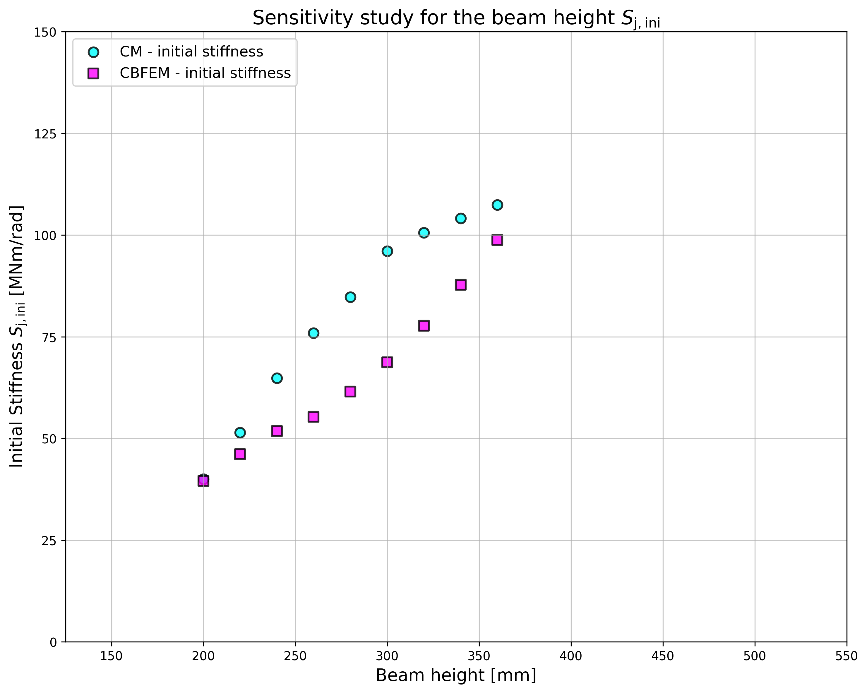
10.2.4 พฤติกรรมโดยรวมและการตรวจสอบ
การเปรียบเทียบพฤติกรรมโดยรวมของจุดต่อโมเมนต์ที่ขอบหลังคาแบบสลักเกลียวที่อธิบายด้วยแผนภาพโมเมนต์-การหมุนได้รับการจัดเตรียมไว้ จุดต่อถูกวิเคราะห์และคำนวณความแข็งแกร่งของคานที่เชื่อมต่อ ลักษณะสำคัญคือความแข็งแกร่งเริ่มต้นที่คำนวณโดย 2/3 Mj,Rd โดยที่ Mj,Rd คือความต้านทานโมเมนต์การออกแบบของจุดต่อ Mc,Rd หมายถึงความต้านทานโมเมนต์การออกแบบของคานที่วิเคราะห์ แผนภาพโมเมนต์-การหมุนแสดงในรูป 10.2.6-10.2.16
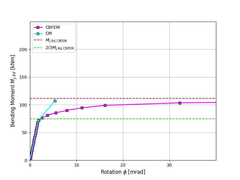
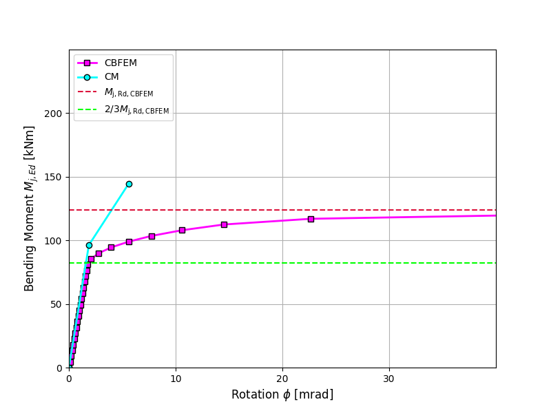
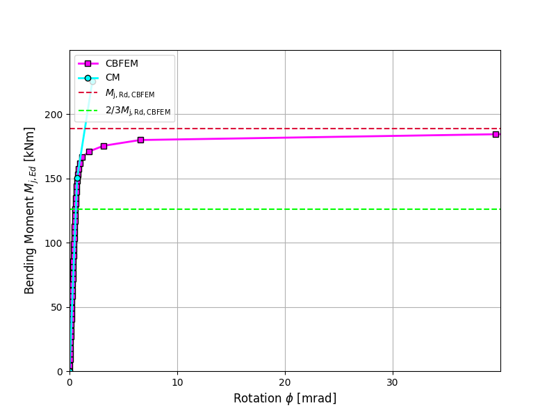
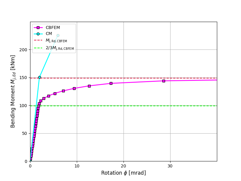
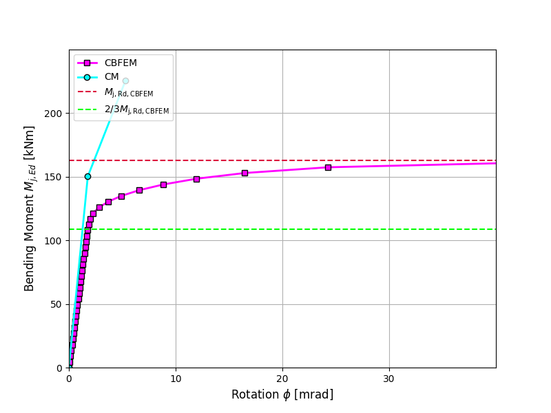
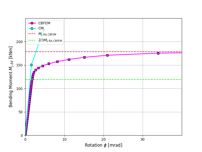
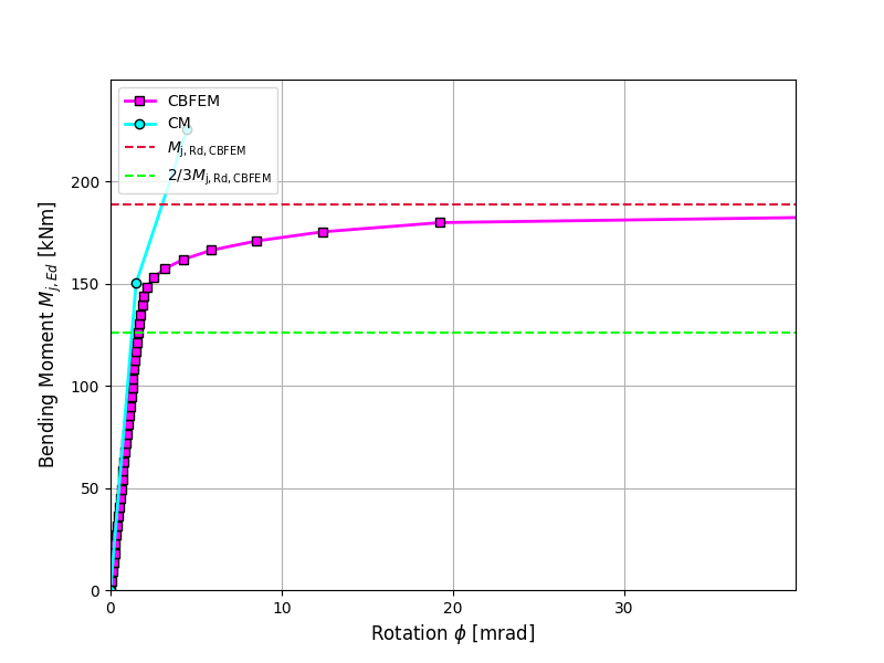
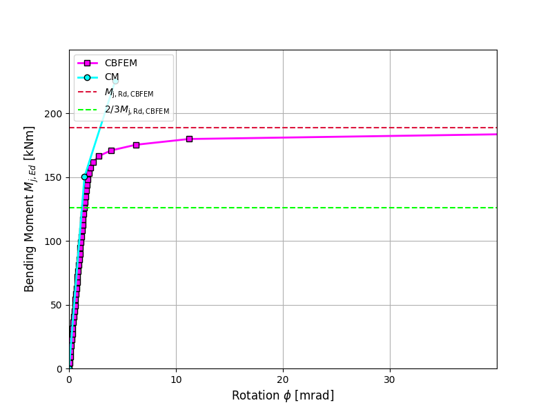
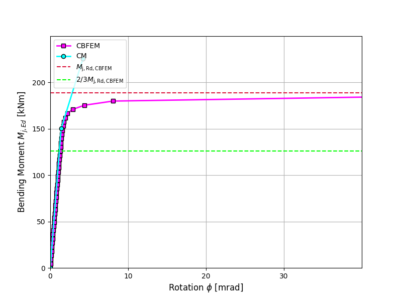
10.2.5 Benchmark case
ข้อมูลนำเข้า
คานและเสา
- เหล็ก S235
- เสา HEB200
- คาน IPE330
รอยเชื่อม
- ความหนาคอรอยเชื่อมปีก af = 8 มม.
- ความหนาคอรอยเชื่อมเว็บ aw = 5 มม.
แผ่นปลาย
- ความหนา tp = 15 มม.
- ความสูง hp = 450 มม.
- ความกว้าง bp = 200 มม.
- สลักเกลียว M24 8.8
- การประกอบสลักเกลียวในรูป 10.2.1
แผ่นเสริมความแข็งเสา
- ความหนา ts = 15 มม.
- ความกว้าง bs = 95 มม.
- สัมพันธ์กับปีกคาน ตำแหน่งบนและล่าง
- ความหนาคอรอยเชื่อม as = 6 มม.
แผ่นเสริมความแข็งแผ่นปลาย
- ความหนา tst = 10 มม.
- ความสูง hst = 90 มม.
- ความหนาคอรอยเชื่อม ast = 5 มม.
ผลลัพธ์
- แรงกระทำ Mj,Ed = 2/3 Mj,Rd = 70 kNm
- ความแข็งแกร่งในการหมุนแบบ secant Sjs = 40 MNm/rad
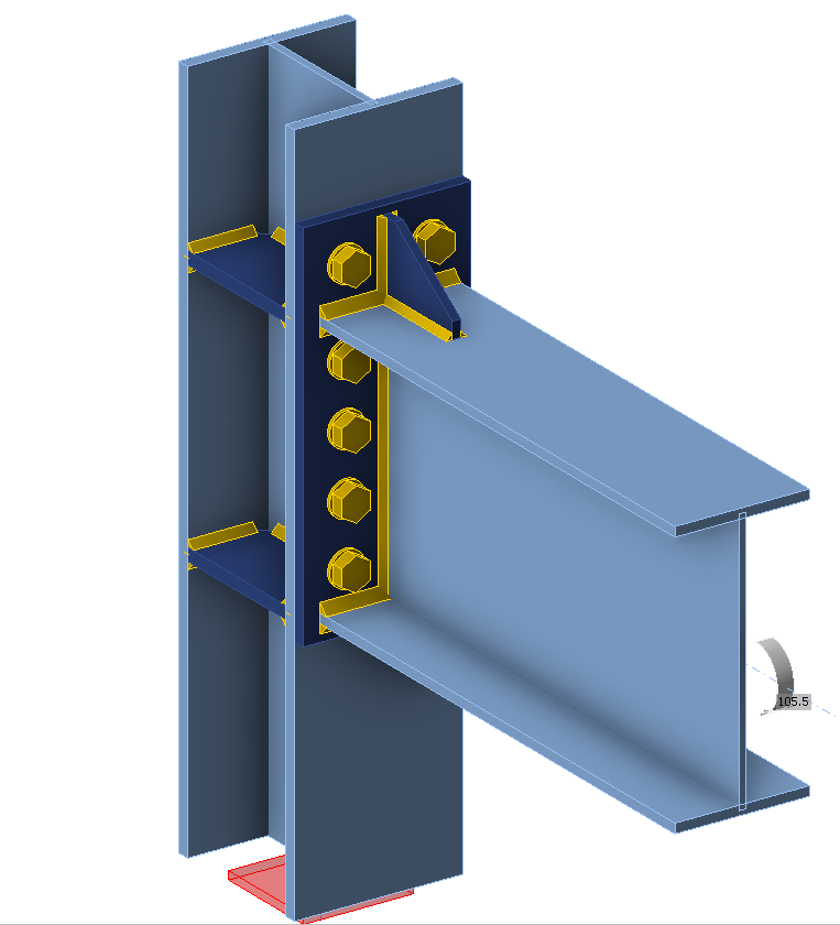
จุดต่อที่ผ่านการรับรองล่วงหน้าสำหรับการใช้งานในพื้นที่แผ่นดินไหว
12.1 โครงการ EQUALJOINTS
โครงการวิจัยของยุโรป EQUALJOINTS จัดทำเกณฑ์การรับรองล่วงหน้าของข้อต่อเหล็กสำหรับ EN 1998-1 เวอร์ชันถัดไป กิจกรรมการวิจัยครอบคลุมการกำหนดมาตรฐานขั้นตอนการออกแบบและการผลิตสำหรับข้อต่อแบบสลักเกลียวหลายประเภท และการเชื่อมต่อแบบ reduced beam section ด้วยโปรไฟล์หนักที่ออกแบบให้ตอบสนองระดับสมรรถนะที่แตกต่างกัน นอกจากนี้ยังมีการพัฒนาโปรโตคอลการรับแรงใหม่สำหรับการรับรองล่วงหน้าของยุโรป ซึ่งเป็นตัวแทนของความต้องการด้านแผ่นดินไหวในยุโรป การทดสอบเชิงทดลองที่มุ่งเน้นการระบุลักษณะแบบวัฏจักรของทั้งเหล็กกล้าคาร์บอนอ่อนของยุโรปและสลักเกลียวความแข็งแรงสูง บรรลุพฤติกรรมที่ต้องการสำหรับข้อต่อที่ผ่านการรับรองล่วงหน้าสี่ประเภท ได้แก่ ข้อต่อสลักเกลียวแบบ haunch, ข้อต่อสลักเกลียวแบบแผ่นปลายยื่นไม่มีแผ่นเสริมความแข็ง, ข้อต่อสลักเกลียวแบบแผ่นปลายยื่นมีแผ่นเสริมความแข็ง และข้อต่อแบบ welded reduced beam section ดังแสดงในรูปที่ 12.1.1 ผลลัพธ์ที่ได้จากการทดลองภายในโครงการ EQUALJOINTS สรุปไว้ใน (Stratan et al. 2017) และ (Tartaglia and D'Aniello, 2017)
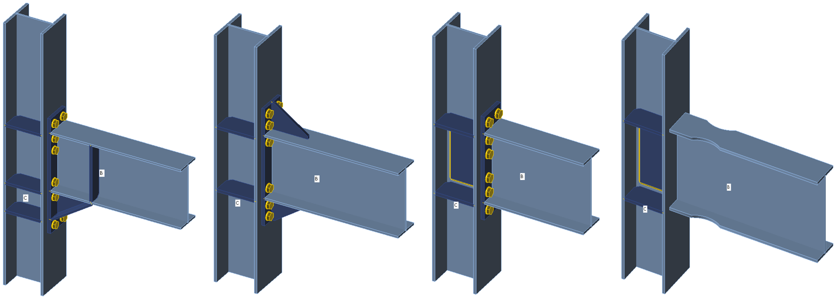
รูปที่ 12.1.1 ข้อต่อโครงสร้างที่ผ่านการรับรองล่วงหน้าในโครงการ EQUALJOINTS
12.2 ข้อต่อแบบแผ่นปลาย
การเชื่อมต่อด้วยสลักเกลียวแบบแผ่นปลายยื่นมีแผ่นเสริมความแข็งเป็นที่นิยมมากที่สุดในอุตสาหกรรมการผลิตโครงสร้างเหล็กของยุโรป และถูกใช้อย่างแพร่หลายในทางปฏิบัติของยุโรปในฐานะข้อต่อต้านทานโมเมนต์ในโครงเหล็กความสูงต่ำถึงปานกลาง เนื่องจากความเรียบง่ายและความประหยัดในการผลิตและการติดตั้ง เกณฑ์การออกแบบและข้อกำหนดที่เกี่ยวข้องสำหรับข้อต่อคานต่อเสาแบบสลักเกลียวแผ่นปลายยื่นมีแผ่นเสริมความแข็งได้รับการศึกษาอย่างละเอียดและอภิปรายอย่างวิพากษ์วิจารณ์ และปัจจุบันได้รับการบัญญัติไว้ใน EN 1998-1:2005 โดยอาศัยการศึกษาเชิงพารามิเตอร์จากการวิเคราะห์ด้วยวิธี Finite Element น่าเสียดายที่ขั้นตอนการออกแบบตามหลัก capacity design ได้รับการพัฒนาเฉพาะในกรอบของวิธีส่วนประกอบเท่านั้น นอกจากนี้ยังคำนึงถึงการมีอยู่ของซี่เสริมและสามารถควบคุมการตอบสนองของข้อต่อสำหรับระดับสมรรถนะที่แตกต่างกัน
ข้อต่อสลักเกลียวแบบแผ่นปลายยื่นไม่มีแผ่นเสริมความแข็งถูกใช้กันทั่วไปในการก่อสร้างโครงสร้างเหล็กเพื่อเชื่อมต่อคานเหล็กรูปตัด I หรือ H กับเสาเหล็กรูปตัด I หรือ H ในกรณีที่ต้องถ่ายโมเมนต์ดัดขนาดใหญ่ การกำหนดค่านี้ช่วยให้การติดตั้งด้วยสลักเกลียวทำได้ง่าย ในขณะที่การเชื่อมแผ่นปลายกับคานดำเนินการโดยอัตโนมัติในโรงงาน ความต้านทานการดัดของการเชื่อมต่อมักจะต่ำกว่าความต้านทานการดัดของชิ้นส่วนที่เชื่อมต่อ ดังนั้นข้อต่อดังกล่าวจึงถือว่าเป็นแบบ partial strength การบรรลุสถานการณ์ equal strength ซึ่งความต้านทานพลาสติกของข้อต่อเท่ากับความต้านทานพลาสติกของหน้าตัดคานโดยประมาณ สามารถทำได้ผ่านการออกแบบที่เหมาะสม ความเหนียวในการดัดขึ้นอยู่กับรายละเอียดของข้อต่อเป็นอย่างมาก ซึ่งมีอิทธิพลต่อรูปแบบการวิบัติ (Jaspart, 1997) หากส่วนประกอบของข้อต่อที่ควบคุมการวิบัติเป็นแบบเหนียว และหากความต้านทานของส่วนประกอบที่เปราะบางสูงกว่าอย่างมีนัยสำคัญ ก็สามารถบรรลุการตอบสนองของข้อต่อแบบเหนียวได้ ในกรณีตรงกันข้าม ไม่ควรพึ่งพาความสามารถของข้อต่อในการก่อตัวเป็น plastic hinge และกระจายแรงภายในเพื่อดูดซับพลังงานในพื้นที่แผ่นดินไหว
สำหรับการเชื่อมต่อต้านทานโมเมนต์แบบ welded reduced beam section หรือที่เรียกว่า dog-bone มีสองกลยุทธ์หลักที่นำมาใช้ คือการเสริมความแข็งแรงของการเชื่อมต่อหรือการลดความแข็งแรงของคาน ในบรรดาสองตัวเลือกสำหรับรูปแบบการลดหน้าตัด การตัดแบบรัศมีมีแนวโน้มที่จะแสดงพฤติกรรมที่เหนียวกว่าค่อนข้างมาก โดยชะลอการแตกหักขั้นสุดท้าย (Jones et al. 2002) อย่างไรก็ตาม งานวิจัยแสดงให้เห็นว่าชิ้นส่วน reduced beam section มีแนวโน้มที่จะเกิดการโก่งเดาะด้านข้างและบิดมากกว่า เนื่องจากพื้นที่ของปีกลดลง การวิจัยเชิงทดลองและเชิงวิเคราะห์เพิ่มเติมที่มุ่งเน้นการใช้งานเสาลึก (Zhang and Ricles, 2006) ระบุว่าการมีแผ่นพื้นคอนกรีตแบบผสมอาจช่วยลดปริมาณการบิดที่เกิดขึ้นในเสาได้อย่างมาก เนื่องจากให้การค้ำยันแก่คานและลดการเคลื่อนตัวด้านข้างของปีกล่าง
ตามขั้นตอนการออกแบบที่พัฒนาขึ้นภายในโครงการ EQUALJOINTS ข้อต่อประกอบด้วยสามส่วนประกอบหลัก ได้แก่ แผ่นเอวเสา, บริเวณการเชื่อมต่อ และบริเวณคาน ดังแสดงในรูปที่ 12.2.1 แต่ละส่วนประกอบหลักได้รับการออกแบบแยกกันตามสมมติฐานเฉพาะ จากนั้นจึงนำเกณฑ์ capacity design มาใช้เพื่อให้ได้วัตถุประสงค์การออกแบบสามประการที่แตกต่างกันสำหรับการประเมินข้อต่อ ได้แก่ ข้อต่อ full strength, equal strength และ partial strength ข้อต่อ full strength ได้รับการออกแบบเพื่อรับประกันการก่อตัวของการเสียรูปพลาสติกทั้งหมดในคาน ซึ่งสอดคล้องกับกฎ capacity design แบบเสาแข็ง-คานอ่อนของ EN 1998-1:2005 ข้อต่อ equal strength มีลักษณะเฉพาะทางทฤษฎีโดยการครากพร้อมกันของส่วนประกอบหลักทั้งหมด ได้แก่ การเชื่อมต่อ, แผ่นเอว และคาน ข้อต่อ partial strength ได้รับการออกแบบให้เกิดการเสียรูปพลาสติกเฉพาะในการเชื่อมต่อหรือแผ่นเอวเสาเท่านั้น ตามความต้านทานของส่วนประกอบหลักการเชื่อมต่อและแผ่นเอวเสาสำหรับทั้งข้อต่อ equal strength และ partial strength สามารถนำการจำแนกประเภทเพิ่มเติมมาใช้ได้ สำหรับแผ่นเอวแข็ง ความต้องการพลาสติกจะกระจุกตัวอยู่ที่การเชื่อมต่อสำหรับข้อต่อ partial strength หรือที่การเชื่อมต่อและคานสำหรับข้อต่อ equal strength สำหรับแผ่นเอวสมดุล ความต้องการพลาสติกจะกระจายระหว่างการเชื่อมต่อและแผ่นเอวเสาสำหรับข้อต่อ partial strength และในการเชื่อมต่อ, แผ่นเอว และคานสำหรับข้อต่อ equal strength สำหรับแผ่นเอวอ่อน ความต้องการพลาสติกจะกระจุกตัวอยู่ที่แผ่นเอวเสาสำหรับข้อต่อ partial strength หรือที่แผ่นเอวและคานสำหรับข้อต่อ equal strength
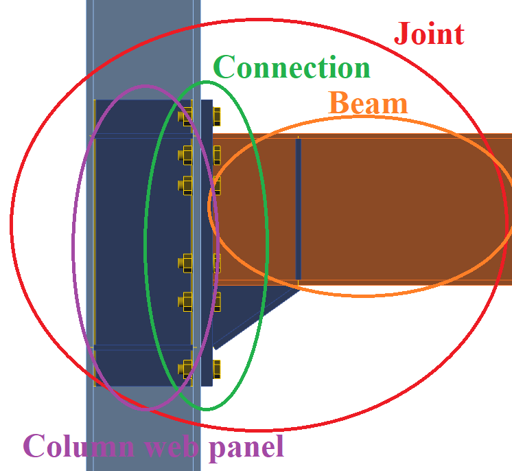
รูปที่ 12.2.1 การแบ่งข้อต่อออกเป็นส่วนประกอบหลัก
ความเหนียวของข้อต่อขึ้นอยู่กับประเภทของรูปแบบการวิบัติและความสามารถในการเสียรูปพลาสติกของส่วนประกอบที่ถูกกระตุ้น ความสามารถในการเสียรูปอาจประมาณได้คร่าวๆ โดยการปฏิบัติตามเกณฑ์ที่พัฒนาขึ้นสำหรับวิธีส่วนประกอบ หรือคำนวณได้อย่างแม่นยำยิ่งขึ้นด้วยวิธี Component-Based Finite Element ตัวอย่างการออกแบบข้อต่อที่ผ่านการรับรองล่วงหน้าสองรูปแบบที่อธิบายไว้ในเอกสารโครงการ EQUALJOINTS และมาตรฐาน ANSI/AISC358-16 นำเสนอด้านล่างโดยพิจารณาพฤติกรรมของส่วนประกอบหลักแยกกัน
12.2.1 การตรวจสอบความถูกต้อง
แบบจำลอง CBFEM ของความแข็งเกร็ง, ความสามารถในการรับแรง และความสามารถในการเสียรูปของข้อต่อที่ผ่านการรับรองล่วงหน้าได้รับการตรวจสอบความถูกต้องโดย Montenegro (2017) จากชุดการทดลองที่มีอยู่จากโครงการ EQUALJOINTS ตัวอย่างของแนวทางแก้ปัญหาโครงสร้างแสดงในรูปที่ 12.2.2 ผลลัพธ์ของการตรวจสอบความถูกต้องของรูปแบบการวิบัติแสดงในรูปที่ 12.2.3 สรุปการตรวจสอบความถูกต้องของความต้านทานและความสามารถในการเสียรูปสำหรับความเครียด 15 % แสดงในรูปที่ 12.2.4 และ 12.2.5
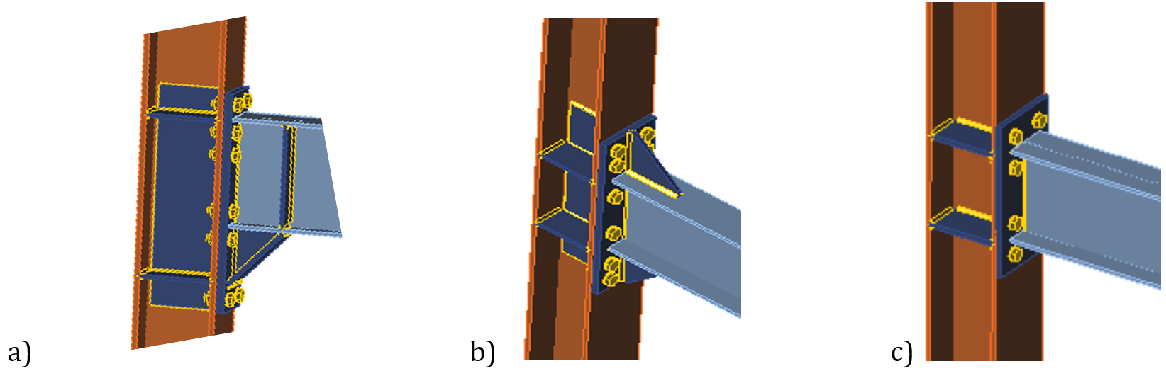
รูปที่ 12.2.2 ข้อต่อที่ใช้สำหรับการตรวจสอบความถูกต้องและการพิสูจน์ a) EH2-TS-35-M และ EH2-TS-45-M, b) ES1-TS-F-M และ ES3-TS-F-M, c) E1-TS-E-M และ E2-TS-E-M
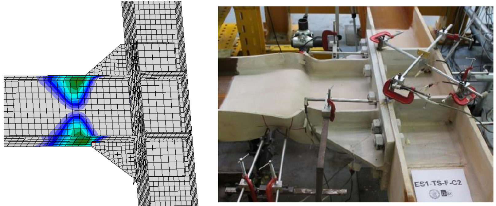
รูปที่ 12.2.3 การตรวจสอบความถูกต้องของรูปแบบการวิบัติของ CBFEM บนข้อต่อแผ่นปลายยื่นพร้อม haunch E1-TS-F-C2 (Tartaglia and D'Aniello, 2017)
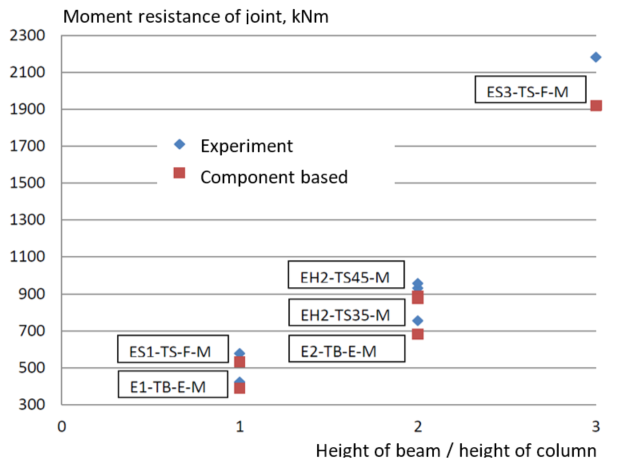
รูปที่ 12.2.4 การตรวจสอบความถูกต้องของความต้านทานของ CBFEM จากการทดลองในโครงการ EQUALJOINTS
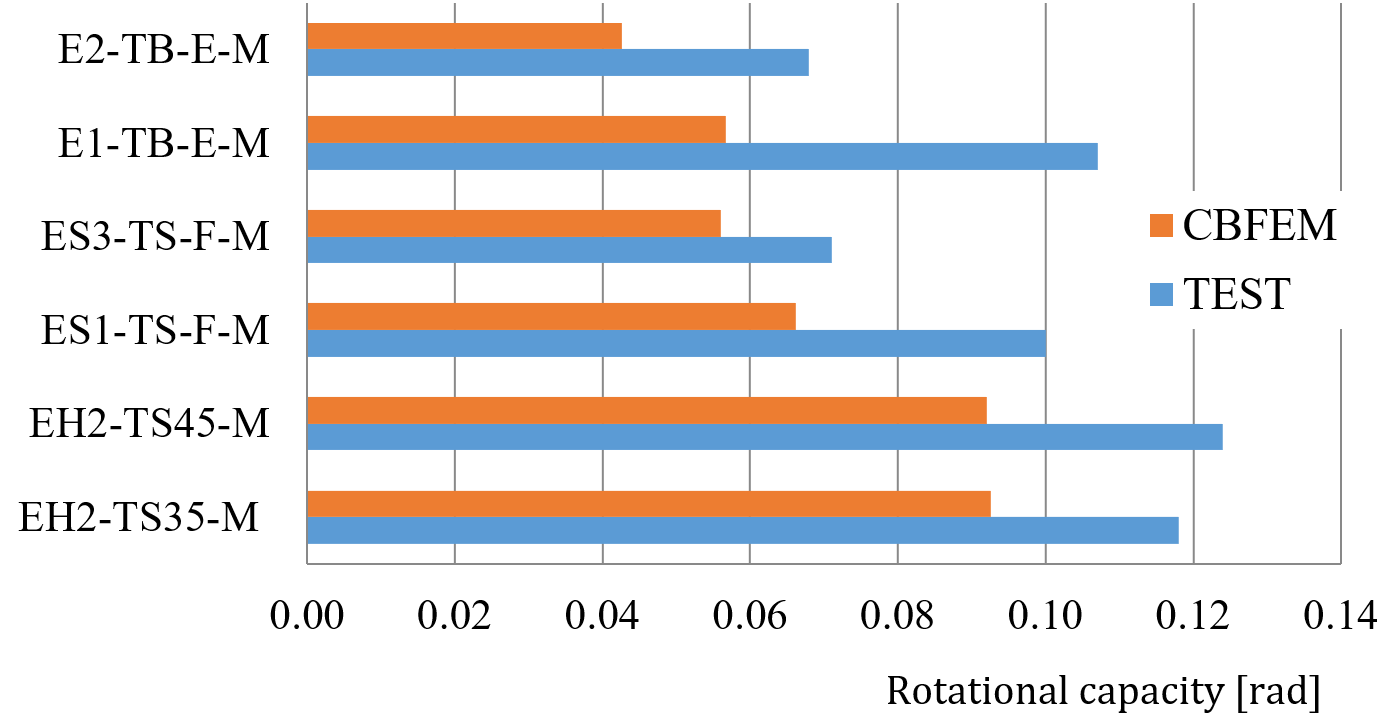
รูปที่ 12.2.5 การตรวจสอบความถูกต้องของความสามารถในการหมุนของ CBFEM จากการทดลองในโครงการ EQUALJOINTS
12.2.2 การพิสูจน์ความถูกต้อง
แบบจำลอง CBFEM ได้รับการพิสูจน์ความถูกต้องเทียบกับวิธีส่วนประกอบตาม Ch. 6 ใน EN 1993-1-8:2006 การคัดเลือกผลลัพธ์นำเสนอในตารางที่ 12.2.1 และรูปที่ 12.2.6 ผลลัพธ์แสดงให้เห็นถึงการสูญเสียความแม่นยำของวิธีส่วนประกอบสำหรับข้อต่อขนาดใหญ่ ซึ่งสมมติฐานคร่าวๆ ของแขนโมเมนต์เป็นตัวกำหนดความแม่นยำ
ตารางที่ 12.2.1 การพิสูจน์ความถูกต้องของ CBFEM เทียบกับวิธีส่วนประกอบ
| ประเภท | ความต้านทาน | |||
| # | วิธีส่วนประกอบ | CBFEM | CBFEM/วิธีส่วนประกอบ | ส่วนประกอบที่กำหนด |
| MR [kNm] | MR [kNm] | [%] | ||
| ข้อต่อแบบ Haunch | ||||
| EH2-TS35-M | 901,2 | 889 | 1 | แผ่นปลายรับแรงดัด |
| EH2-TS45-M | 959,3 | 875 | 10 | แผ่นปลายรับแรงดัด |
| 4.2 | 876,1 | 1 016 | −16 | ปีกเสารับแรงดัด |
| 264 | 545,4 | 573 | −5 | ปีกเสารับแรงดัด |
| 267 | 1 998,9 | 2 100 | −5 | แผ่นปลายรับแรงดัด |
| ข้อต่อแบบยื่นมีแผ่นเสริมความแข็ง | ||||
| ES1-TS-F-M | 547,5 | 533 | 3 | ปีกเสารับแรงดัด |
| ES3-TS-F-M | 1389 | 1 920 | −27 | ปีกเสารับแรงดัด |
| ข้อต่อแบบยื่นไม่มีแผ่นเสริมความแข็ง | ||||
| E1-TB-E-M | 347,8 | 389 | −11 | แผ่นปลายรับแรงดัด |
| E2-TB-E-M | 577,0 | 681 | −15 | แผ่นปลายรับแรงดัด |
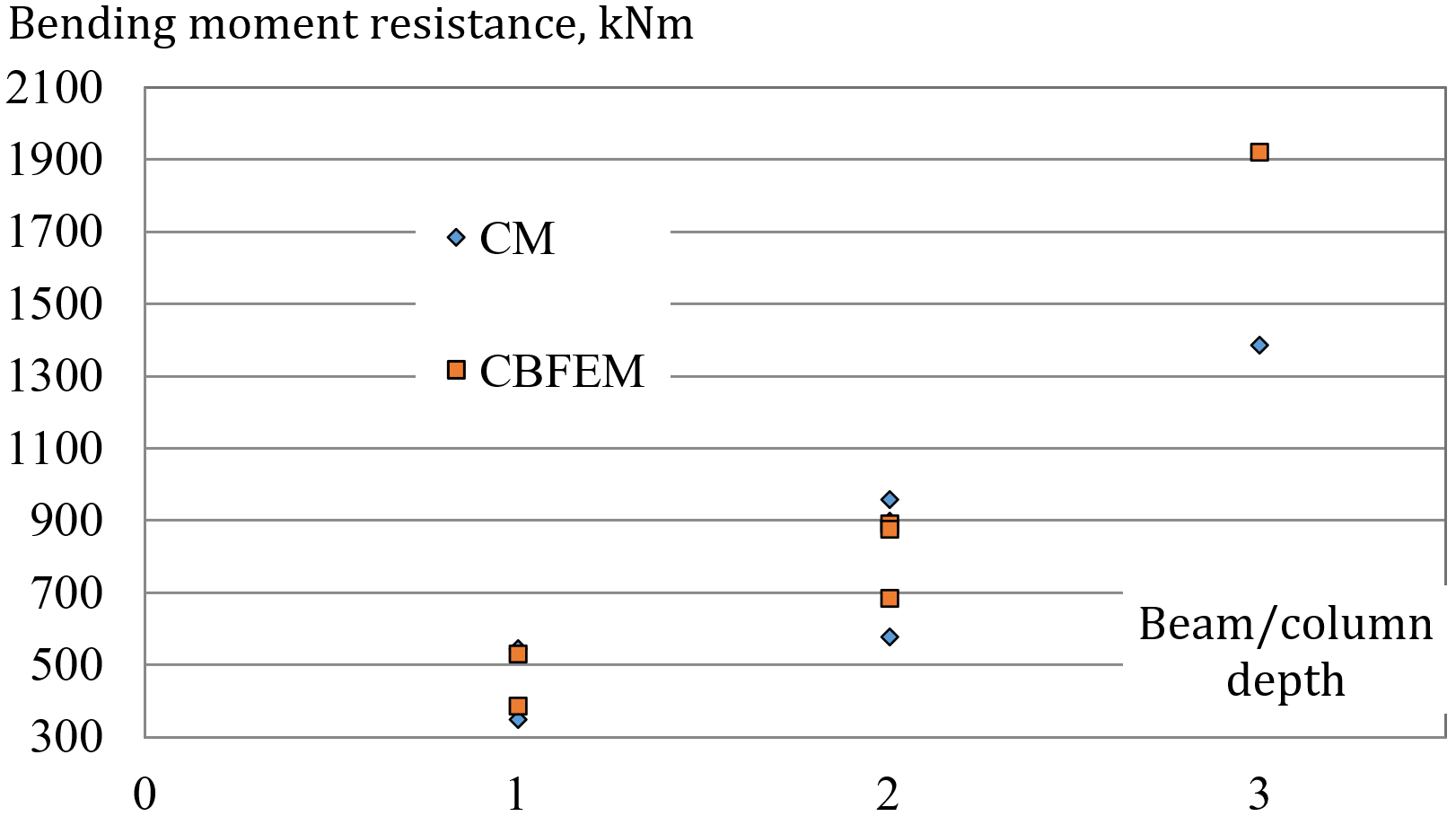
รูปที่ 12.2.6 การพิสูจน์ความถูกต้องของความต้านทานของ CBFEM เทียบกับวิธีส่วนประกอบ
ข้อต่อแบบ haunch ด้านเดียวสามแบบได้รับการอธิบายอย่างละเอียดใน (Landolfo et al. 2017) และ (Equaljoints application) ข้อต่อรับโมเมนต์ดัดทั้งแบบ sagging และ hogging และแรงเฉือนที่สอดคล้องกัน แผ่นเอวเสาได้รับการเสริมด้วยแผ่นเสริม ดังนั้นส่วนประกอบที่กำหนดจึงเป็น T-stub ของแผ่นปลายหรือปีกเสา แกนหมุนถูกสมมติให้อยู่ที่จุดศูนย์กลางของปีกคานบนสำหรับโมเมนต์ดัดแบบ sagging และที่กึ่งกลางของ haunch สำหรับโมเมนต์ดัดแบบ hogging ตำแหน่งของ plastic hinge ถูกสมมติให้อยู่ที่หน้าของแผ่นเสริมความแข็งที่ปลายของ haunch โมเมนต์ดัดที่หน้าเสาที่ใช้สำหรับการตรวจสอบการเชื่อมต่อจะเพิ่มขึ้นตามแรงเฉือนที่สอดคล้องกัน ดังแสดงในรูปที่ 12.2.7
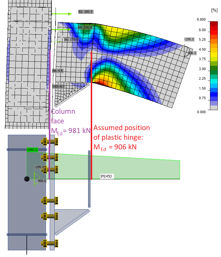
รูปที่ 12.2.7 ตำแหน่งของ plastic hinge และแผนภาพโมเมนต์ดัดในข้อต่อแบบ haunch
ตารางที่ 12.2.2 ความต้านทานของส่วนประกอบโดยวิธีส่วนประกอบสำหรับข้อต่อแบบ haunch
| ความต้านทานของส่วนประกอบโดยวิธีส่วนประกอบ | #4.2 (IPE450 ถึง HEB340) | #264 (IPE360 ถึง HEB280) | #267 (IPE600 ถึง HEB500) |
| โมเมนต์ที่ plastic hinge [kNm] | 906 | 543 | 1869 |
| แรงเฉือน [kN] | 295 | 148 | 561 |
| โมเมนต์ที่หน้าเสา [kNm] | 981 | 573 | 2105 |
| ความต้านทานของ haunch [kNm] | 956 | 582 | 1903 |
| แรงเฉือนที่กระทำต่อแผ่นเอวเสา [kN] | 1581 | 1035 | 2447 |
| ความต้านทานแรงเฉือนของแผ่นเอวเสา [kN] | 1632 | 1203 | 2774 |
| T-stub - แผ่นปลาย - โมเมนต์ hogging [kNm] | 1019 | 573 | 1999 |
| T-stub - แผ่นปลาย - โมเมนต์ sagging [kNm] | 1081 | 697 | 2318 |
| T-stub - ปีกเสา - โมเมนต์ hogging [kNm] | 876 | 545 | 2015 |
| T-stub - ปีกเสา - โมเมนต์ sagging [kNm] | 929 | 580 | 2107 |
ค่าสัมประสิทธิ์ strain-hardening ถูกเลือกเป็น 1,2 ตามที่แนะนำโดย EN 1993-1-8:2006 และรายงานฉบับสุดท้ายของโครงการ Equaljoints (EN 1998-1:2005 แนะนำค่า 1,1) ค่าสัมประสิทธิ์ overstrength ถูกสมมติเป็น 1,25 (Landolfo et al. 2017) เหล็กทั้งหมดเป็นเกรด S355 ความต้านทานของส่วนประกอบแต่ละส่วนสรุปไว้ในตารางที่ 12.2.2 การตรวจสอบที่แสดงเป็นตัวหนาไม่ผ่านเกณฑ์ โปรดทราบว่าความต้านทานของ haunch คือความต้านทานพลาสติกของหน้าตัดคานพร้อม haunch ที่แผ่นปลาย ความแข็งแรงของคานถูกสมมติให้เพิ่มขึ้นตามค่าสัมประสิทธิ์ overstrength ที่ตำแหน่ง plastic hinge แต่ไม่ใช่ที่แผ่นปลาย หากใช้ค่าสัมประสิทธิ์ overstrength ที่แผ่นปลายด้วย ความต้านทานนี้จะสูงกว่า ดังนั้น ความต้านทานต่ำสุดถัดไป คือ T-stub – แผ่นปลาย จึงถูกสมมติให้กำหนดความต้านทานของข้อต่อหมายเลข 267 ไม่มีข้อต่อที่ตรวจสอบใดที่ตรงตามข้อกำหนดสำหรับข้อต่อ full-strength อย่างไรก็ตาม ความต้านทานใกล้เคียงมาก และข้อต่อเป็นแบบ equal-strength แผ่นเอวเสาในทุกกรณีมีความแข็งแรง
รูปแบบการวิบัติที่กำหนดโดย CBFEM คือการวิบัติของสลักเกลียวพร้อมการครากของแผ่น โดยหลักคือแผ่นปลาย, ปีกเสา และ haunch ตาม CBFEM ข้อต่อหมายเลข 4.2 และหมายเลข 264 เป็นแบบ full-strength และข้อต่อหมายเลข 267 เป็นแบบ equal-strength แผ่นเอวเสามีความแข็งแรงในทุกกรณี
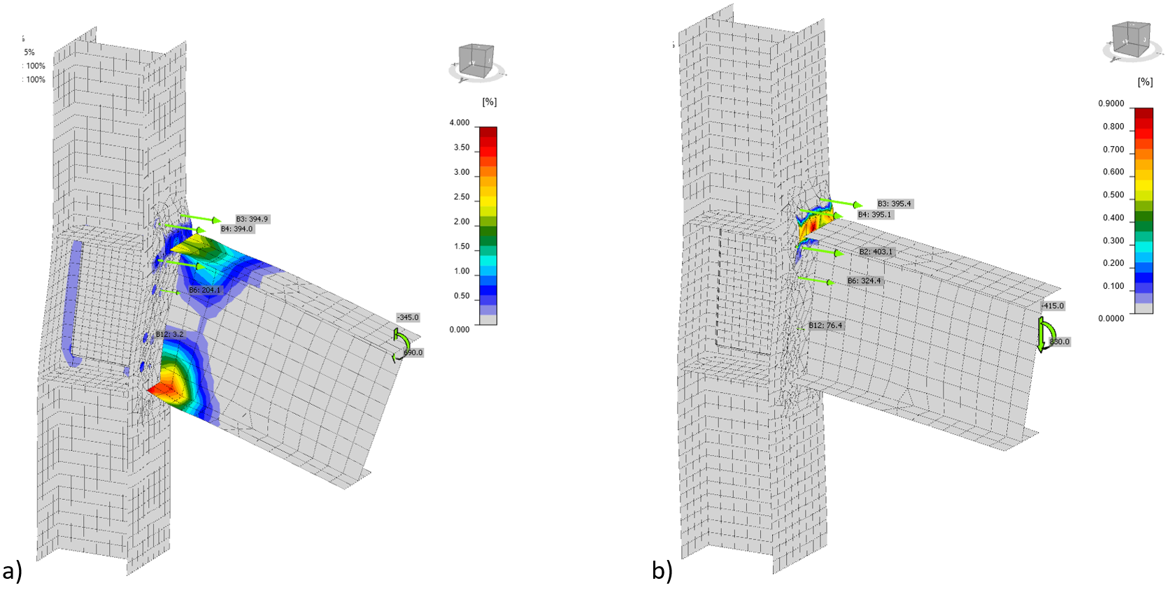
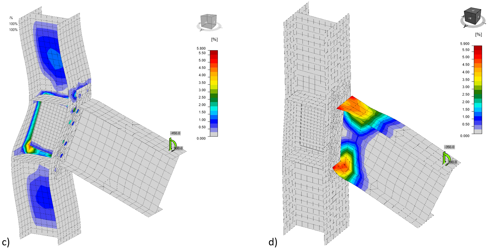
รูปที่ 12.2.8 ความเครียดที่ความต้านทานสำหรับ a) ข้อต่อทั้งหมด, b) เฉพาะส่วนประกอบหลักการเชื่อมต่อแบบสลักเกลียวแผ่นปลาย c) เฉพาะส่วนประกอบหลักแผ่นเอวเสารับแรงเฉือนพร้อมแผ่นเสริม d) เฉพาะส่วนประกอบหลักคาน
12.2.3 ข้อต่อแบบแผ่นปลายยื่นไม่มีแผ่นเสริมความแข็ง
สำหรับการศึกษาความไว ได้เลือกข้อต่อแบบแผ่นปลายยื่นไม่มีแผ่นเสริมความแข็งที่ผ่านการรับรองล่วงหน้า คาน IPE 450 เชื่อมต่อกับเสา HEB 300 ด้วยแผ่นปลายยื่นหนา 25 มม. พร้อมสลักเกลียว M30 10.9 จำนวนสิบสองตัว โดยมีและไม่มีแผ่นเสริมแผ่นเอวหนา 10 มม. เหล็กเกรด S 355 ถูกใช้สำหรับแผ่นทั้งหมด เพื่อกำหนดการมีส่วนร่วมของแต่ละส่วนประกอบหลักแยกกัน แผนภาพวัสดุของส่วนประกอบหลักที่เลือกเป็นแบบ elastoplastic ในขณะที่ส่วนที่เหลือของข้อต่อใช้แผนภาพวัสดุแบบยืดหยุ่นเท่านั้น ความเครียดที่ความต้านทานของข้อต่อทั้งหมด, แผ่นเอวเสารับแรงเฉือนพร้อมแผ่นเสริมเท่านั้น และการเชื่อมต่อแบบสลักเกลียวแผ่นปลายเท่านั้น ถูกเปรียบเทียบกับส่วนประกอบหลักคานเท่านั้นในรูปที่ 12.2.8 อิทธิพลของแต่ละส่วนประกอบหลักต่อพฤติกรรมของข้อต่อนำเสนอในรูปที่ 12.2.9 ซึ่งแสดงแผ่นเอวเสาที่มีและไม่มีแผ่นเสริม พฤติกรรมของข้อต่อแสดงให้เห็นความต้านทานที่สูงกว่าของส่วนประกอบหลักการเชื่อมต่อ
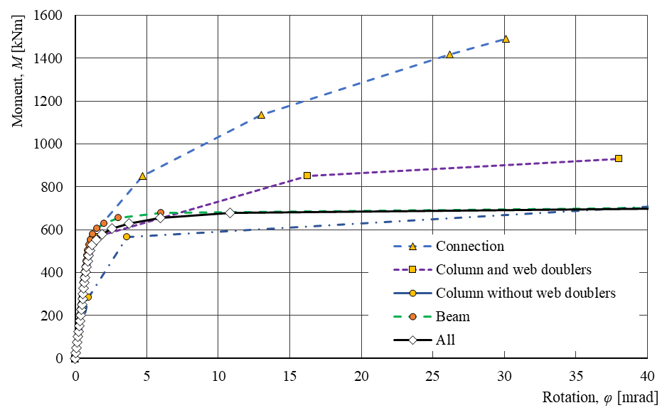
รูปที่ 12.2.9 อิทธิพลของส่วนประกอบหลัก ได้แก่ แผ่นเอวเสาพร้อมแผ่นเสริมรับแรงเฉือน,
การเชื่อมต่อแบบสลักเกลียวแผ่นปลาย และคาน ต่อพฤติกรรมของข้อต่อทั้งหมด
12.2.4 ตำแหน่งของจุดศูนย์กลางแรงอัด
สำหรับข้อต่อแบบแผ่นปลาย EN 1993-1-8:2006 ระบุว่าจุดศูนย์กลางแรงอัดอยู่ที่กึ่งกลางความหนาของปีกคาน หรือที่ปลายของ haunch ในกรณีของข้อต่อแบบ haunch ผลการทดลองและเชิงตัวเลขแสดงให้เห็นว่าตำแหน่งของจุดศูนย์กลางแรงอัดขึ้นอยู่กับทั้งประเภทของข้อต่อและความต้องการการหมุน เนื่องจากการก่อตัวของรูปแบบพลาสติกที่มีการมีส่วนร่วมของส่วนประกอบข้อต่อแต่ละส่วนแตกต่างกัน (Landolfo et al. 2017) ตามขั้นตอนการออกแบบด้วยวิธีส่วนประกอบที่เสนอและอาศัยทั้งผลการทดลองและเชิงตัวเลข คาดว่าจะเกิดการสัมผัสที่ประมาณจุดเซนทรอยด์ของหน้าตัดที่ประกอบด้วยปีกคานและแผ่นเสริมซี่ สำหรับข้อต่อแบบแผ่นปลายมีแผ่นเสริมความแข็ง หรือที่ประมาณ 0,5 ของความสูง haunch ในกรณีของข้อต่อแบบ haunch สมมติฐานคร่าวๆ นี้ได้รับการปรับปรุงให้แม่นยำยิ่งขึ้นด้วยขั้นตอน CBFEM ซึ่งให้ค่าที่ถูกต้องระหว่างการรับแรงและการครากเริ่มต้นของส่วนต่างๆ ของข้อต่อ
ผลลัพธ์ที่นำเสนอแสดงให้เห็นความแม่นยำที่ดีของ CBFEM ที่ได้รับการพิสูจน์ความถูกต้องเทียบกับ ROFEM และตรวจสอบความถูกต้องเทียบกับการทดลอง EQUALJOINTS และวิธีส่วนประกอบ ซึ่งเปิดโอกาสให้พิจารณาพฤติกรรมของส่วนประกอบหลักแยกกัน และตำแหน่งของแกนสะเทินอย่างแม่นยำตามการรับแรง/การเกิดพลาสติก
12.3 ข้อต่อแบบ welded reduced beam section
ข้อต่อแบบ welded reduced beam section ที่ผ่านการรับรองล่วงหน้าตาม ANSI/AISC 358-16 ถูกเลือกสำหรับการศึกษานี้ คาน IPE 450 เชื่อมต่อกับเสา HEB 300 ด้วยรอยเชื่อมชนที่ปีกและแผ่น Fin หนา 12 มม. พร้อมสลักเกลียวอัดแรงล่วงหน้า M30 10.9 จำนวนสามตัว โดยมีและไม่มีแผ่นเสริมแผ่นเอวหนา 10 มม. ดังแสดงในรูปที่ 12.3.1 เหล็กทั้งหมดที่ใช้เป็นเกรด S355
ความเครียดที่ความต้านทานสูงสุดของข้อต่อทั้งหมดและส่วนประกอบหลักแผ่นเอวเสารับแรงเฉือนพร้อมแผ่นเสริมเท่านั้น แสดงในรูปที่ 12.3.2 อิทธิพลของแต่ละส่วนประกอบหลักต่อพฤติกรรมของข้อต่อนำเสนอในรูปที่ 12.3.3 ซึ่งแสดงแผ่นเอวเสาที่มีและไม่มีแผ่นเสริม ข้อต่อแสดงให้เห็นว่าความต้านทานของส่วนประกอบหลักของข้อต่อได้รับการปรับให้เหมาะสมอย่างดี
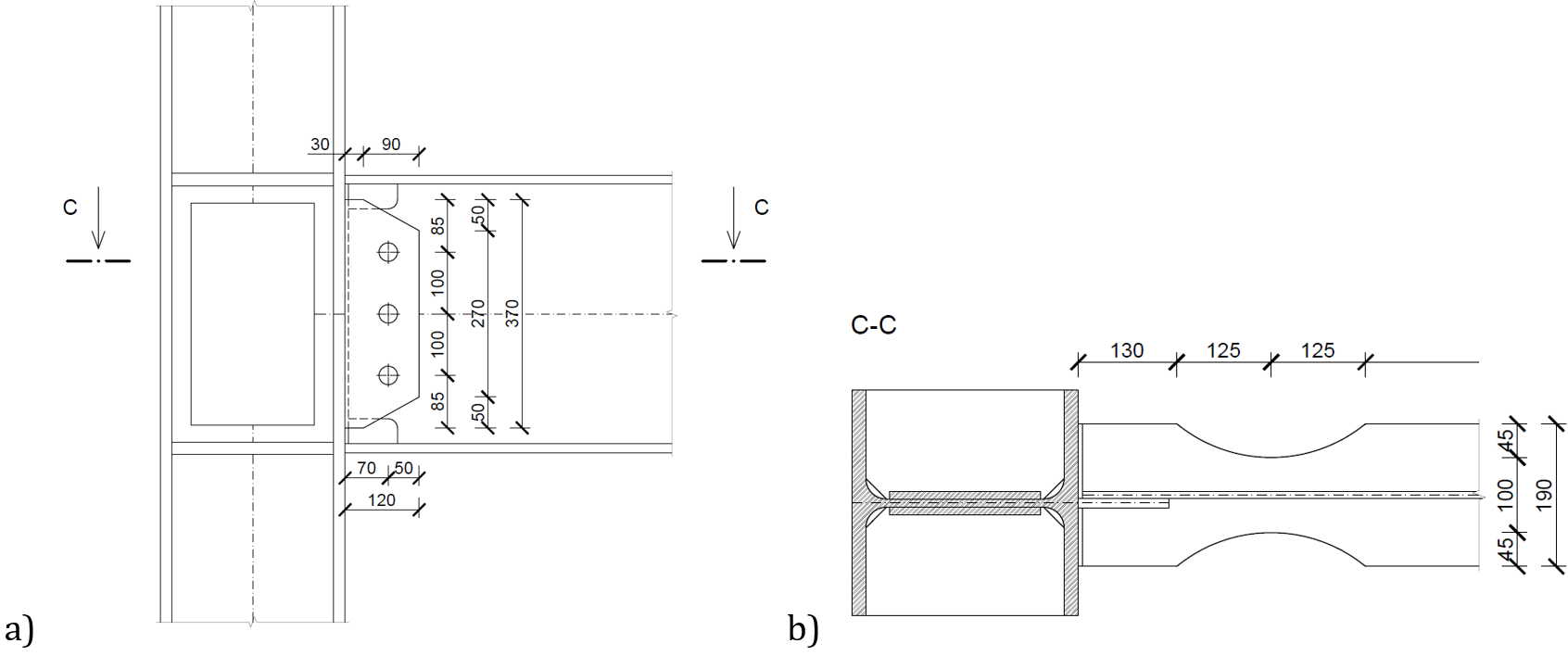
รูปที่ 12.3.1 ข้อต่อ reduced beam section, a) คานพร้อมหน้าตัดที่ลดลง, b) แผ่นเอวเสาพร้อมแผ่นเสริมรับแรงเฉือน, การเชื่อมต่อแบบสลักเกลียวแผ่นปลาย,
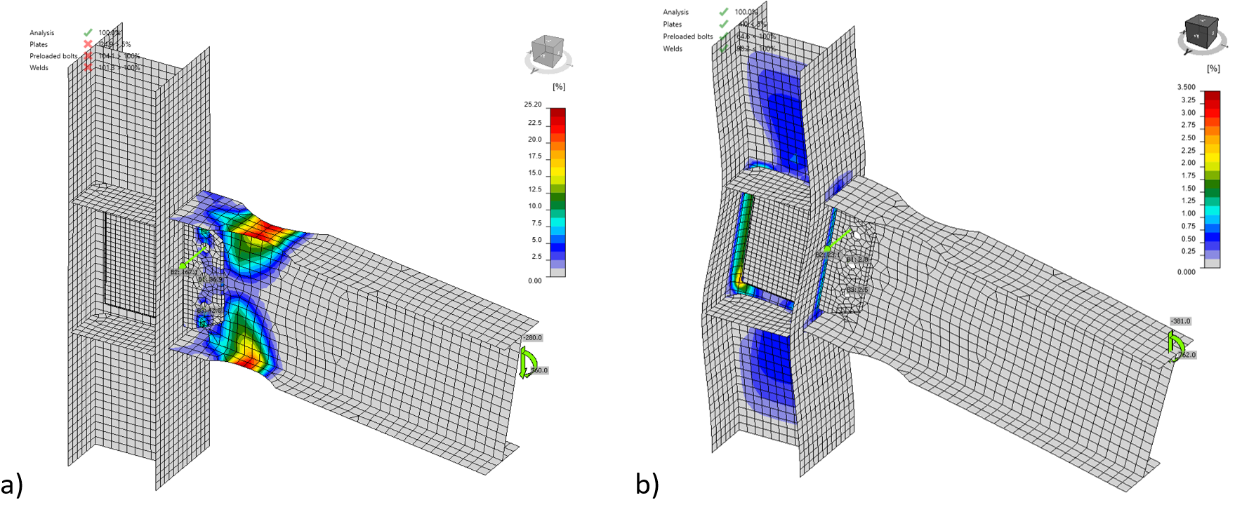
รูปที่ 12.3.2 ความเครียดที่ความต้านทานสำหรับ a) ข้อต่อทั้งหมด และ b) เฉพาะส่วนประกอบหลักแผ่นเอวเสาพร้อมแผ่นเสริมรับแรงเฉือน
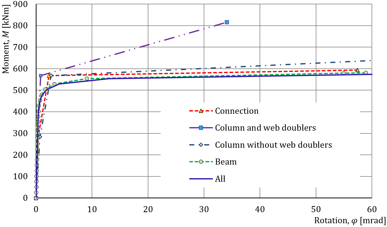
รูปที่ 12.3.3 อิทธิพลของส่วนประกอบหลักต่อพฤติกรรมของข้อต่อทั้งหมดในแผนภาพ M-φ
เอกสารอ้างอิง
EN 1993-1-8, Eurocode 3, Design of steel structures – Part 1-8: Design of joints, CEN, Brussels, 2005.
Jones S.L., Fry GT., Engelhardt M.D. Experimental evaluation of cyclically loaded reduced beam section moment connections. Journal of Structural Engineering. 128 (4), 441–451, 2002.
Landolfo R. et al. Design of Steel Structures for Buildings in Seismic Areas, ECCS Eurocode Design Manual. Wiley, 2017.
Stratan A., Maris C, Dubina D, and Neagu C. Experimental prequalification of bolted extended end plate beam to column connections with haunches. ce/papers, 1(2–3), 414–423, 2017.
Tartaglia R, D'Aniello M. Nonlinear performance of extended stiffened end-plate bolted beam-to-column joints subjected to column removal. The Open Civil Engineering Journal Vol 11, Issue Suppl-1, 369–383, 2017.
Zhang X., Ricles J.M. Experimental evaluation of reduced beam section connections to deep columns. Journal of Structural Engineering. 132 (3), 346-357, 2006.