- Download and install the latest version of IDEA StatiCa
- Make sure that you are using a supported version of your FEA solution
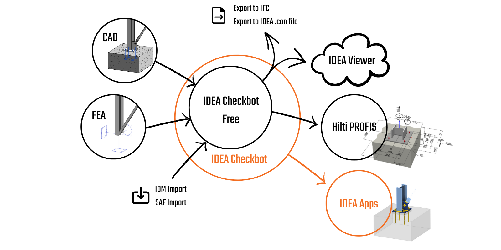
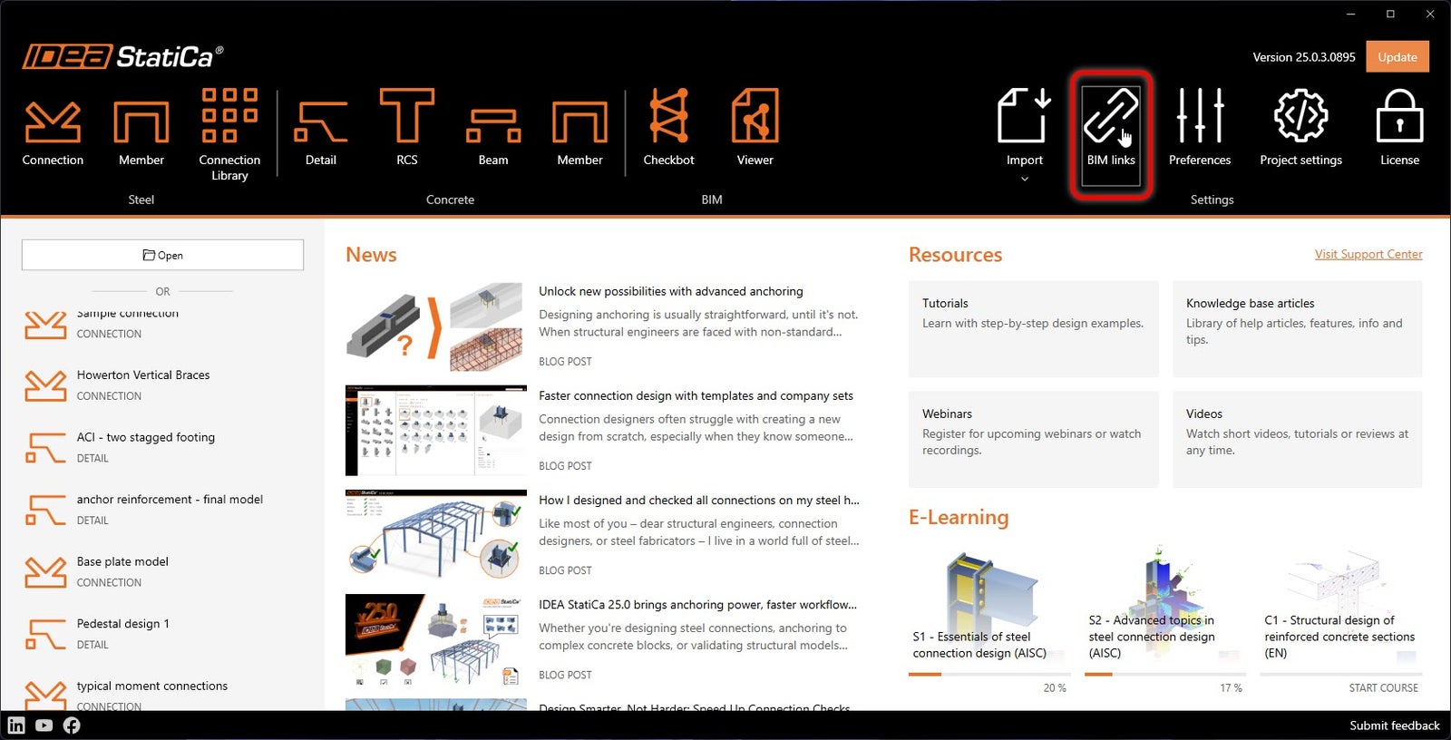
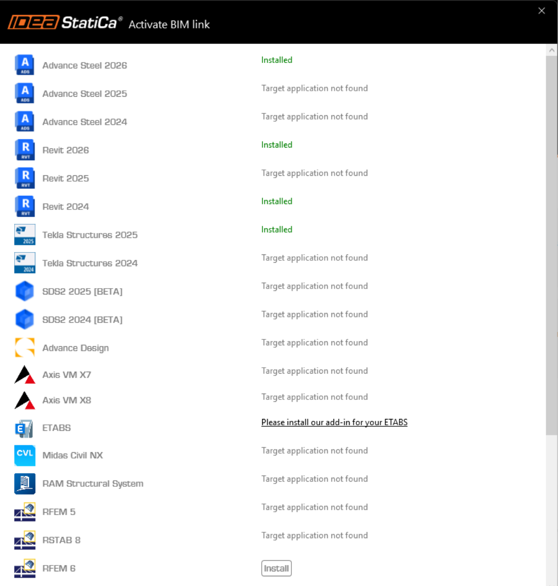
IDEA StatiCa integrates BIM links into your FEA software during its installation. You can check the status and eventually integrate more BIM links by running IDEA StatiCa and opening the BIM links. Please note that some FEA software require additional steps to fully activate their BIM link to IDEA StatiCa.
A notification "Do you want to allow this app to make changes to your device?" may appear, if so, please confirm with the Yes button.
By clicking Install, the BIM link for the selected software is integrated. The screen also tells you the status of other BIM links.
How to use the link
We have two RSA models for you to use: EN (for EC3 and European sections) or BS (for EC3 and British Standard sections).
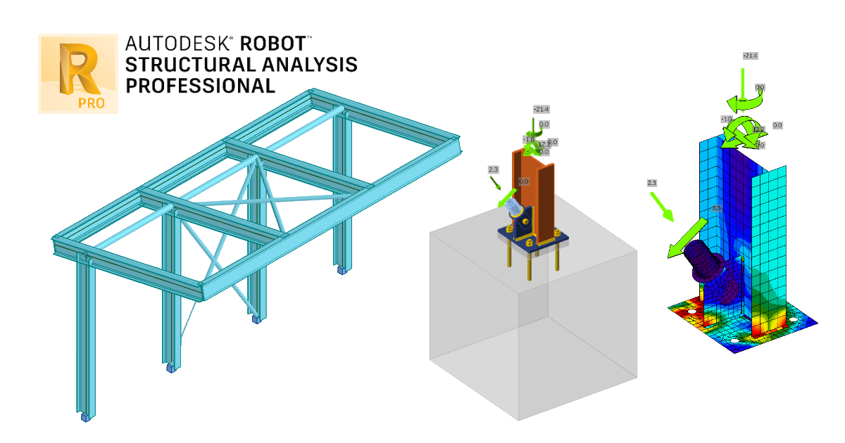
Open the model which best suits your region in Robot Structural Analysis, calculate and save it.
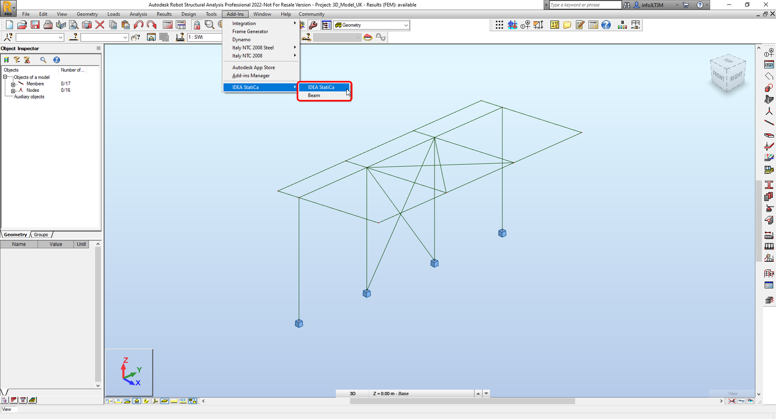
The BIM link is automatically integrated. You can find it in the top ribbon under Add-Ins -> IDEA StatiCa -> IDEA StatiCa. This will open the Checkbot application.
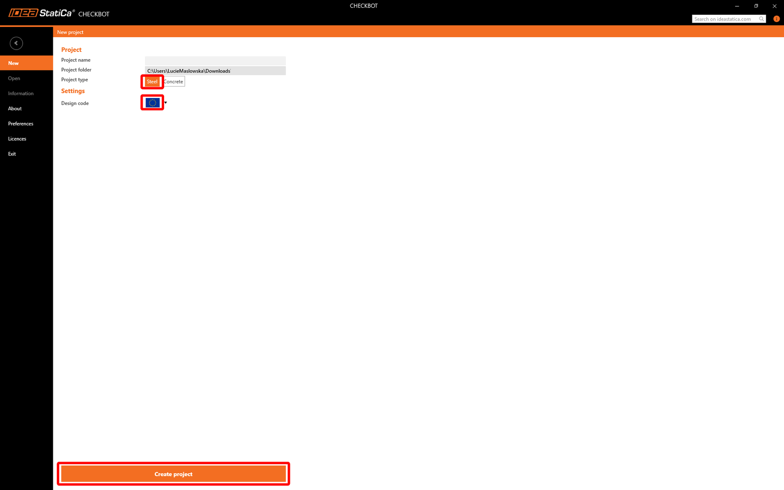
Select the New option with project type Steel and design code EN. Then select Create project.
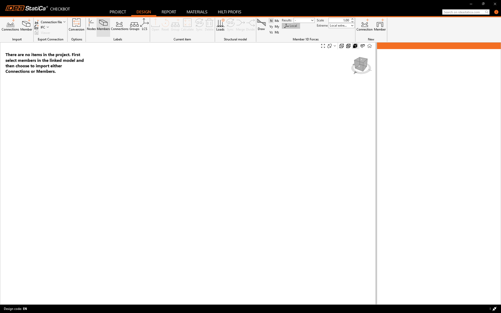
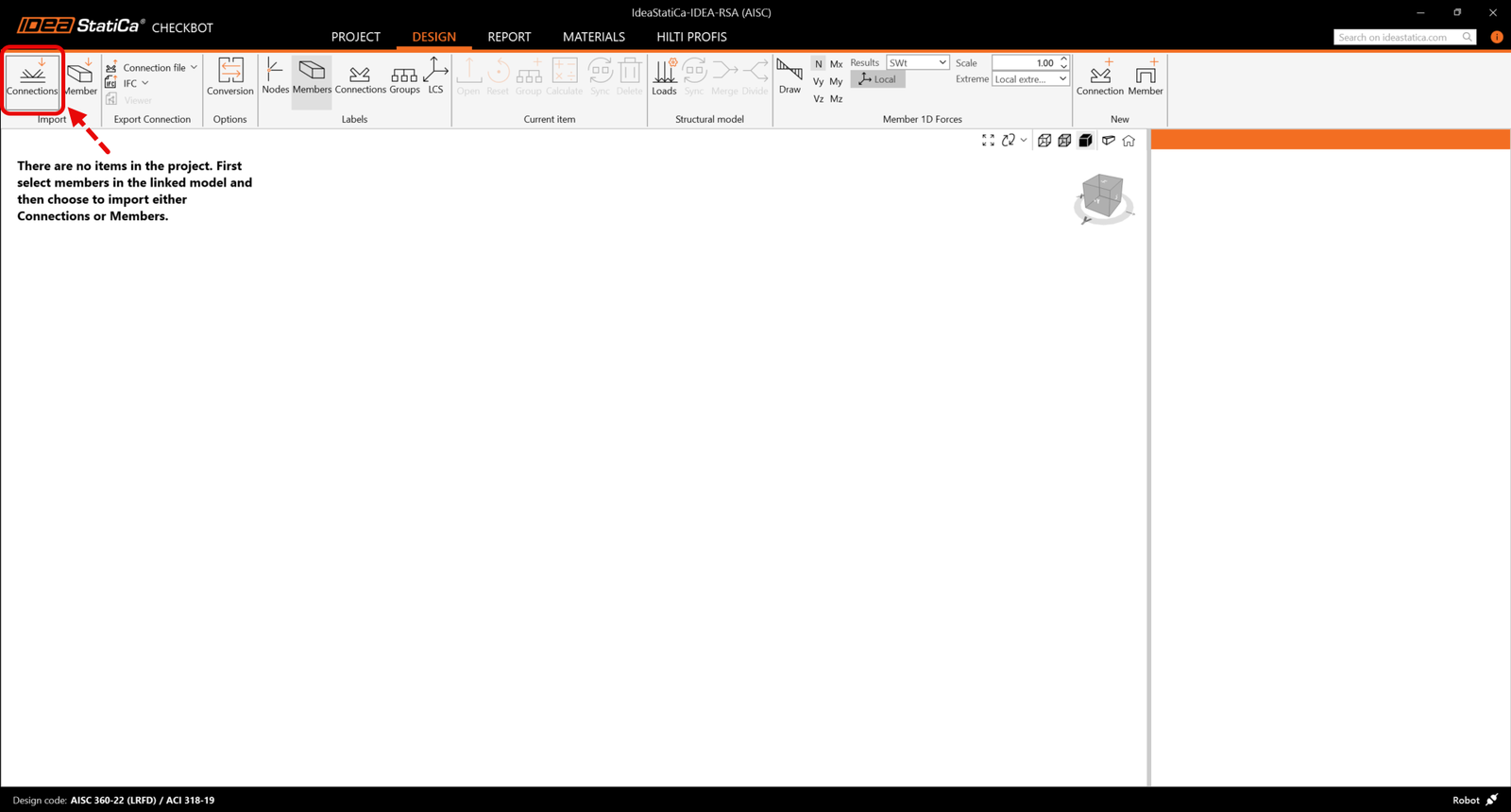
The new Checkbot project is ready to import connections from Robot Structural Analysis.
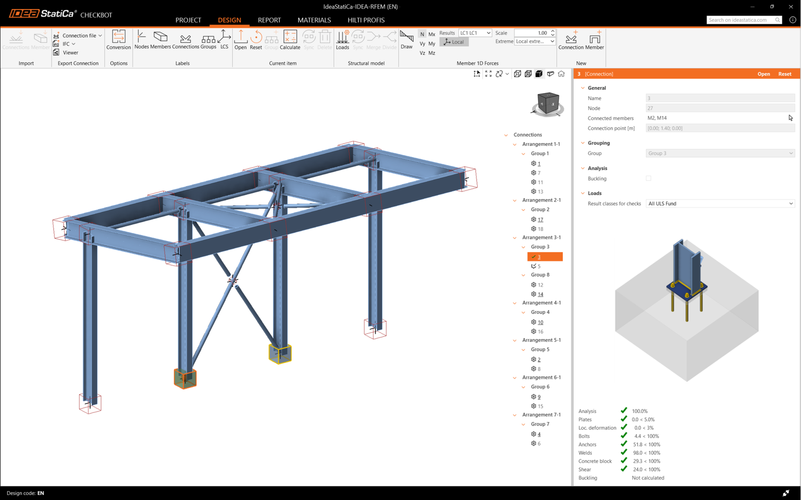
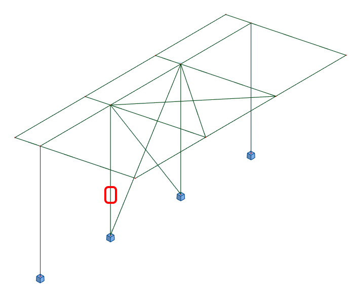
In Robot Structural Analysis, select one of the inside columns with bracing making sure you also select the lowest node.
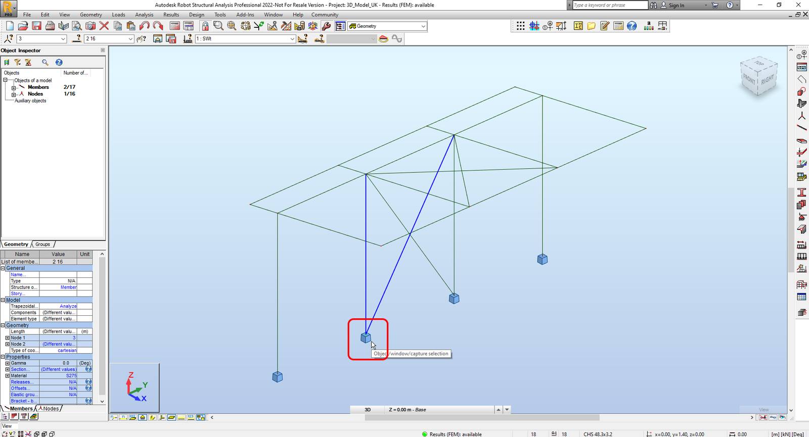
Then in Checkbot select Connections.
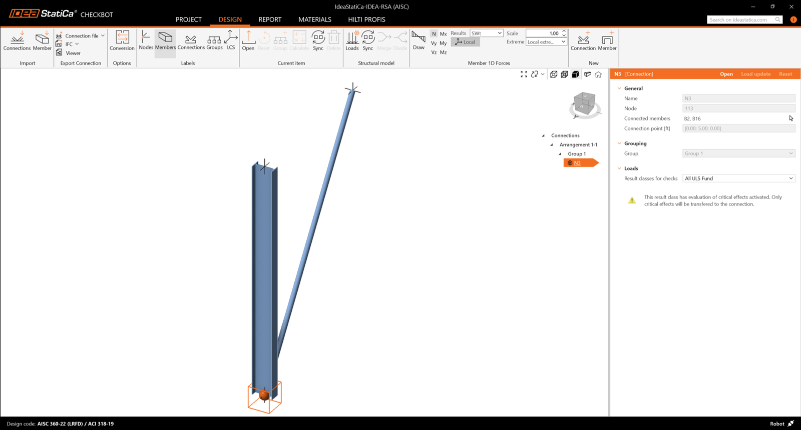
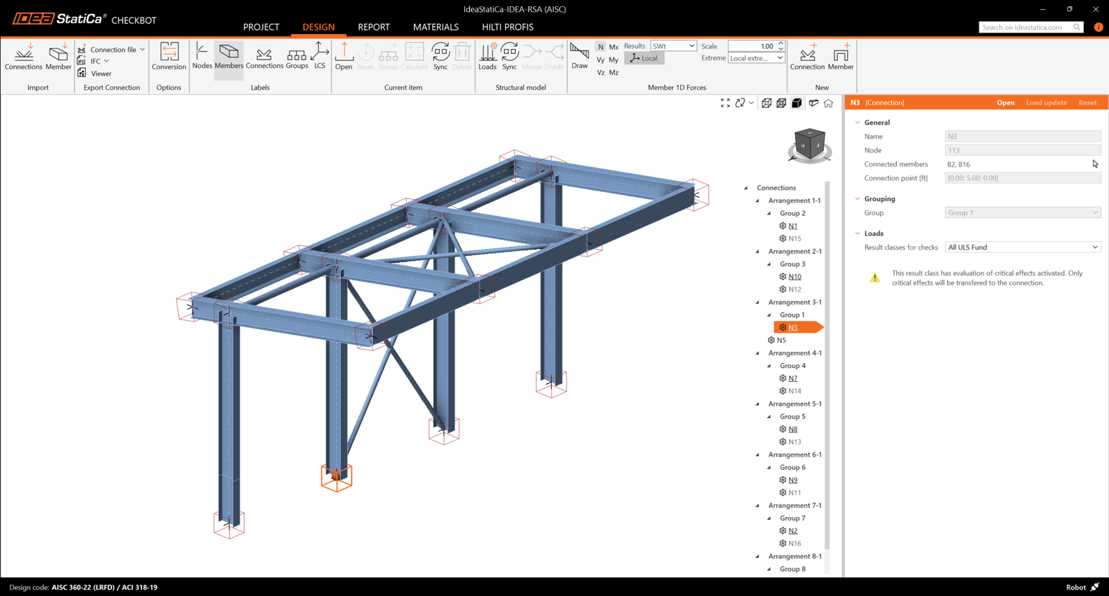
This will import the column and its load effects into Checkbot - with the same coordinates, orientations, and section sizes as per the FEA model.
Please note that your node and member numbering might be different.
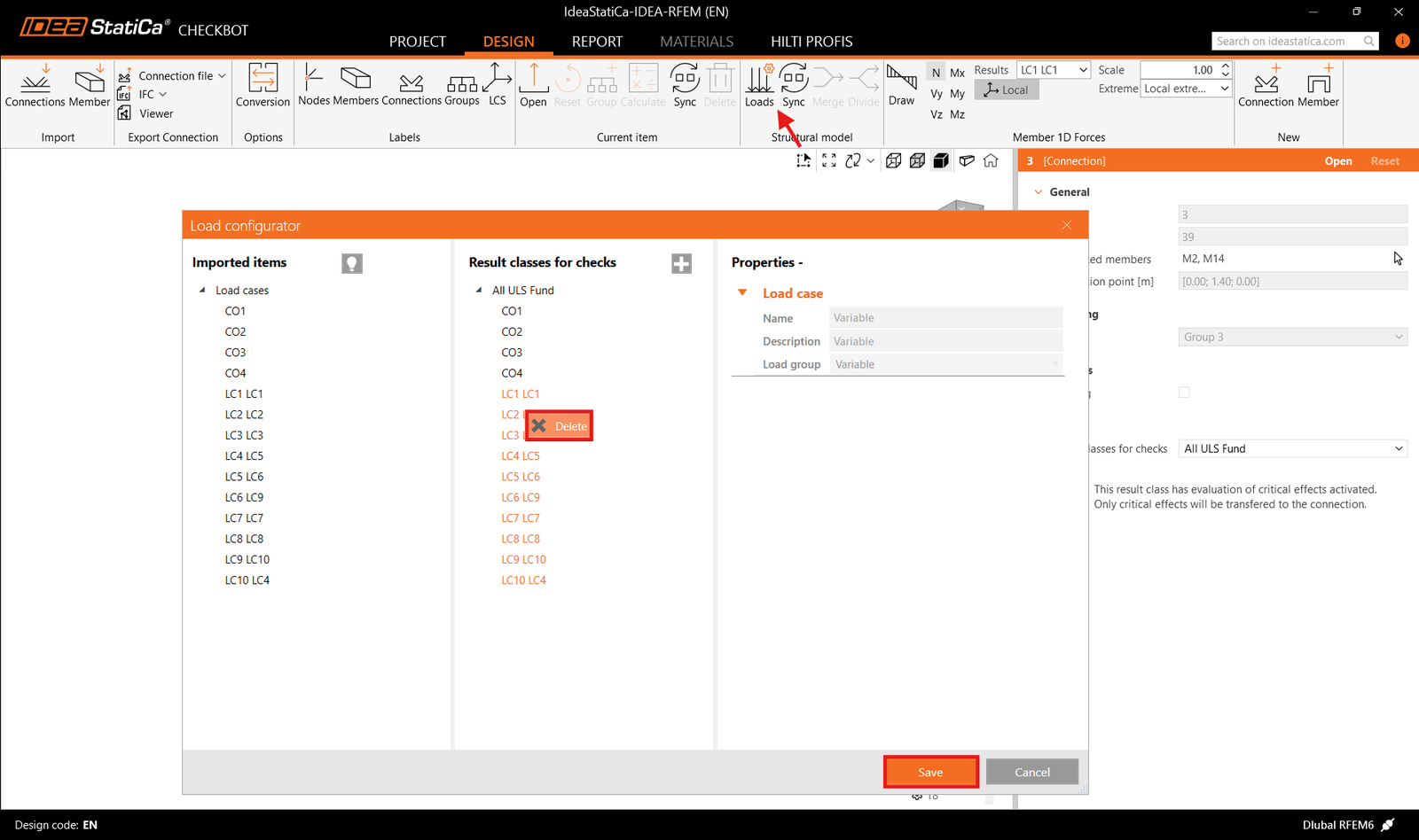
Before running the analysis, make sure to review the Result classes for checks and adjust the load cases accordingly. In the Load configurator dialog, you can see all imported load cases and load combinations on the left and the result classes used for checks in the middle. If some load cases are not relevant for your design verification, exclude them by right-clicking on the selected loads and removing them from the result classes list.
Please note the 3D workspace is designed to show an overview of the imported structure and not a detailed view of the actual connections. For more information on Checkbot, see here.
For several FEA solutions, you can also import multiple connections into Checkbot in the same manner as above. Instead of selecting one node and the connected members, you can select multiple nodes and members and import them all at once.
In the list of project items under Connections and with a connection highlighted in Checkbot you can either right-mouse click and select Open or click the ribbon command Open to start designing, code-checking, and reporting.
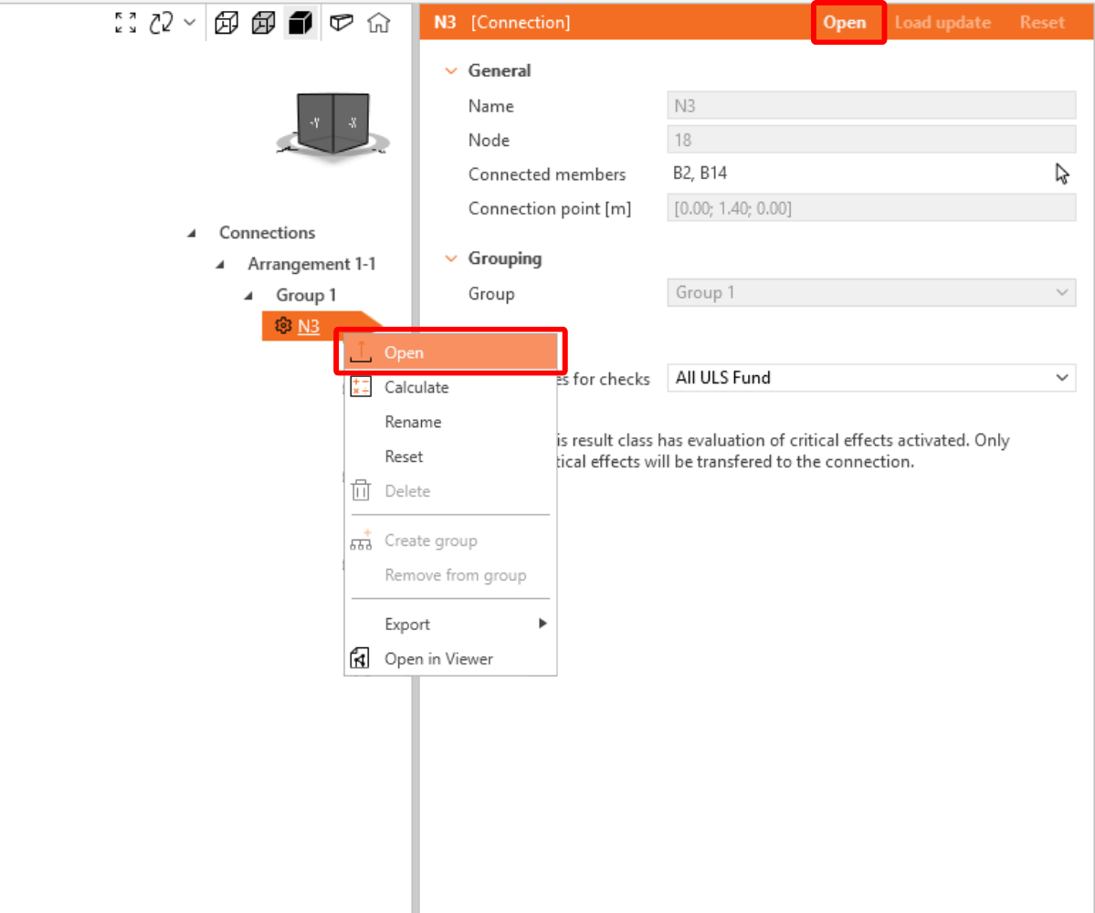
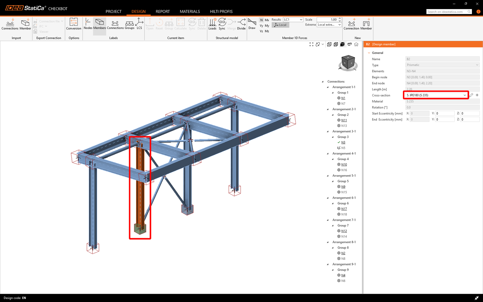
The settings of members are taken from the original FEA application. You can, however, change the section size of any member on the main Checkbot screen, but this will break the link with the FEA application in this session unless it's synchronized again.
The imported connection is opened in the IDEA StatiCa Connection application.
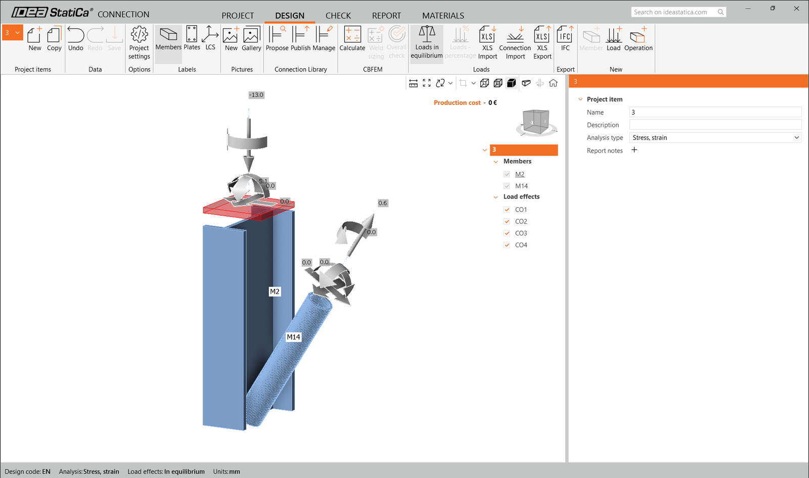
You may see none or different Load effects from your FEA solution, depending on how the load case combinations have been defined. By default, IDEA StatiCa will choose the most critical for code-checking purposes. (* Some BIM solutions are not able to store the load case combination results)
For more information on Load effects, see here.
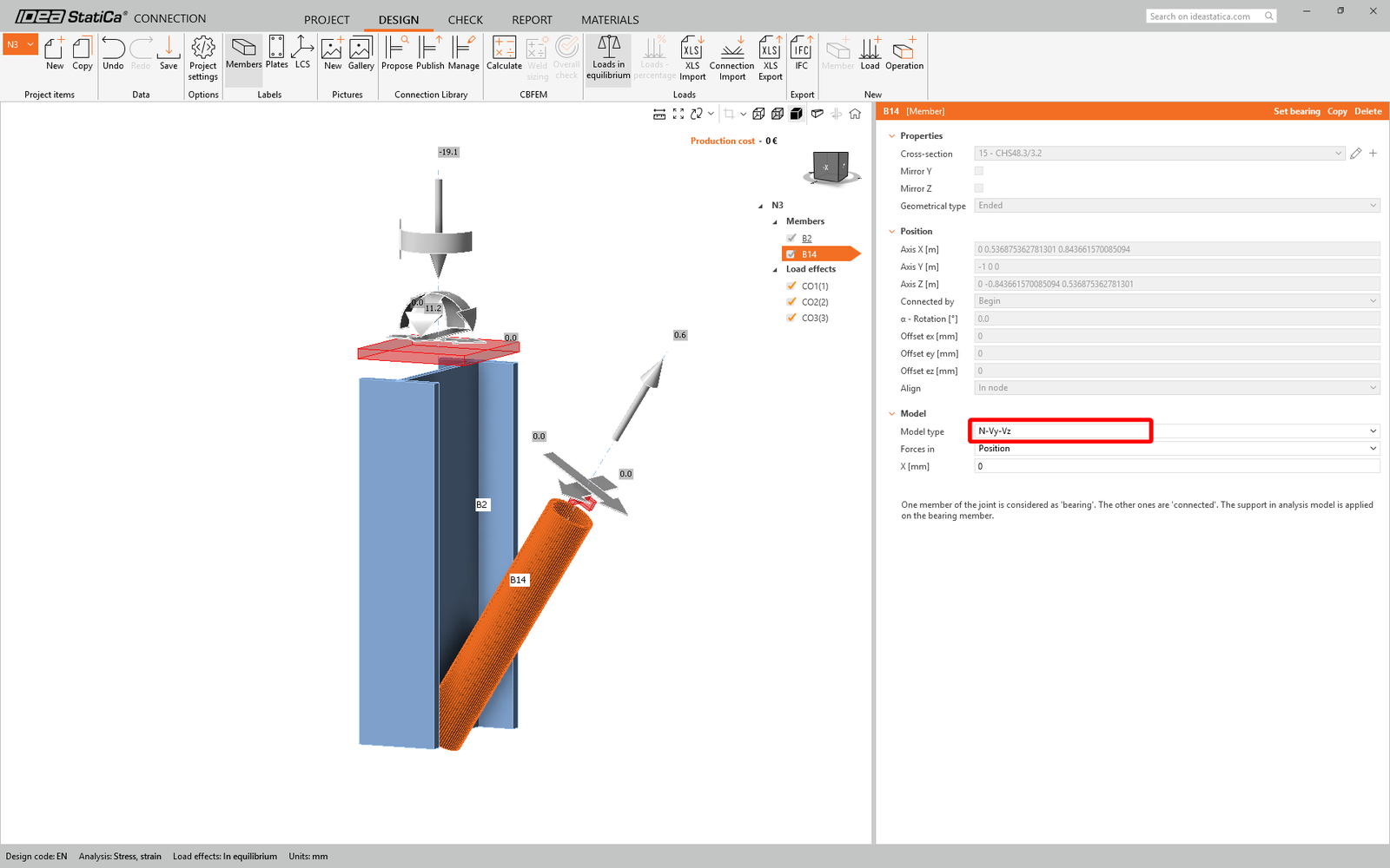
We are going to be using a single bolt connection for the diagonal brace. For this type of connection, we must also change the Model type of the brace member to N-Vy-Vz. Select the brace in the list of Members and modify the Model type in the drop-down list.
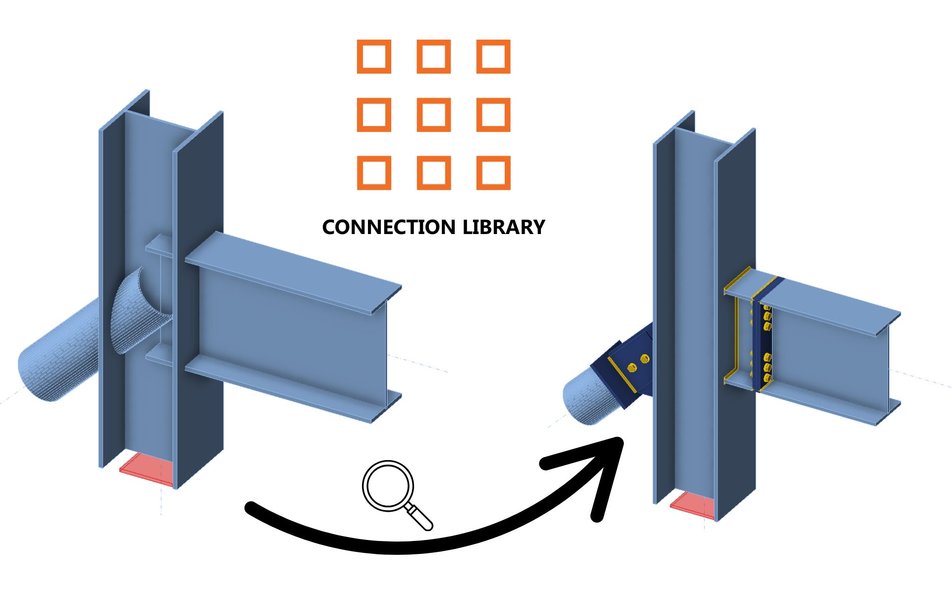
We are going to use the Connection Library to generate a connection. Select Propose and IDEA StatiCa will put forward possible solutions for the current geometry.

Connection Library shows you the possible solutions for the current geometry. Choose the template Column I base plate 4 bolts diagonal bolted weak and press OK.
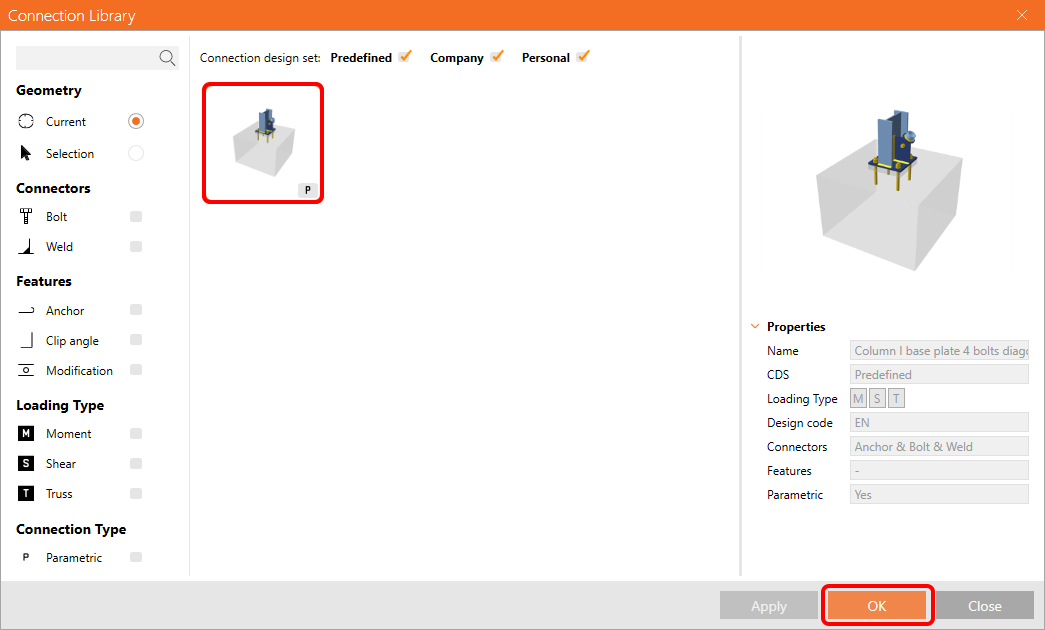
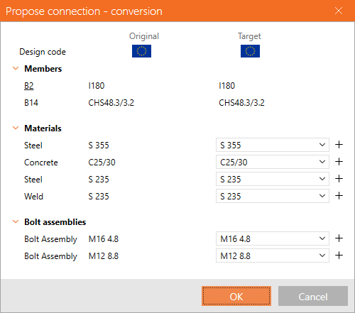
Accept the proposed values in the conversion tab and press OK.
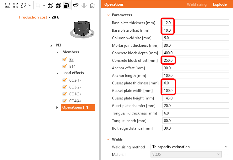
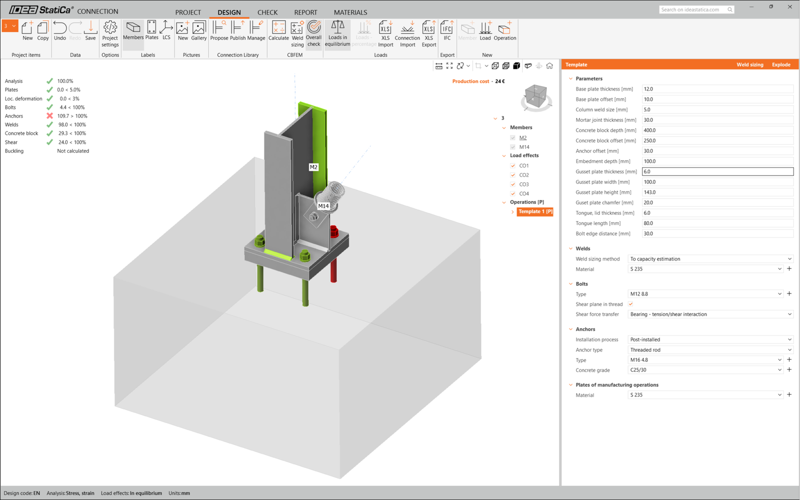
Edit the parameters of this template to fit the desired design – Base plate thickness to 12 mm, Base plate offset to 10 mm, Concrete block offset to 250 mm, Gusset plate thickness to 6 mm, and Gusset plate width to 100 mm.
This is what the initial connection looks like.
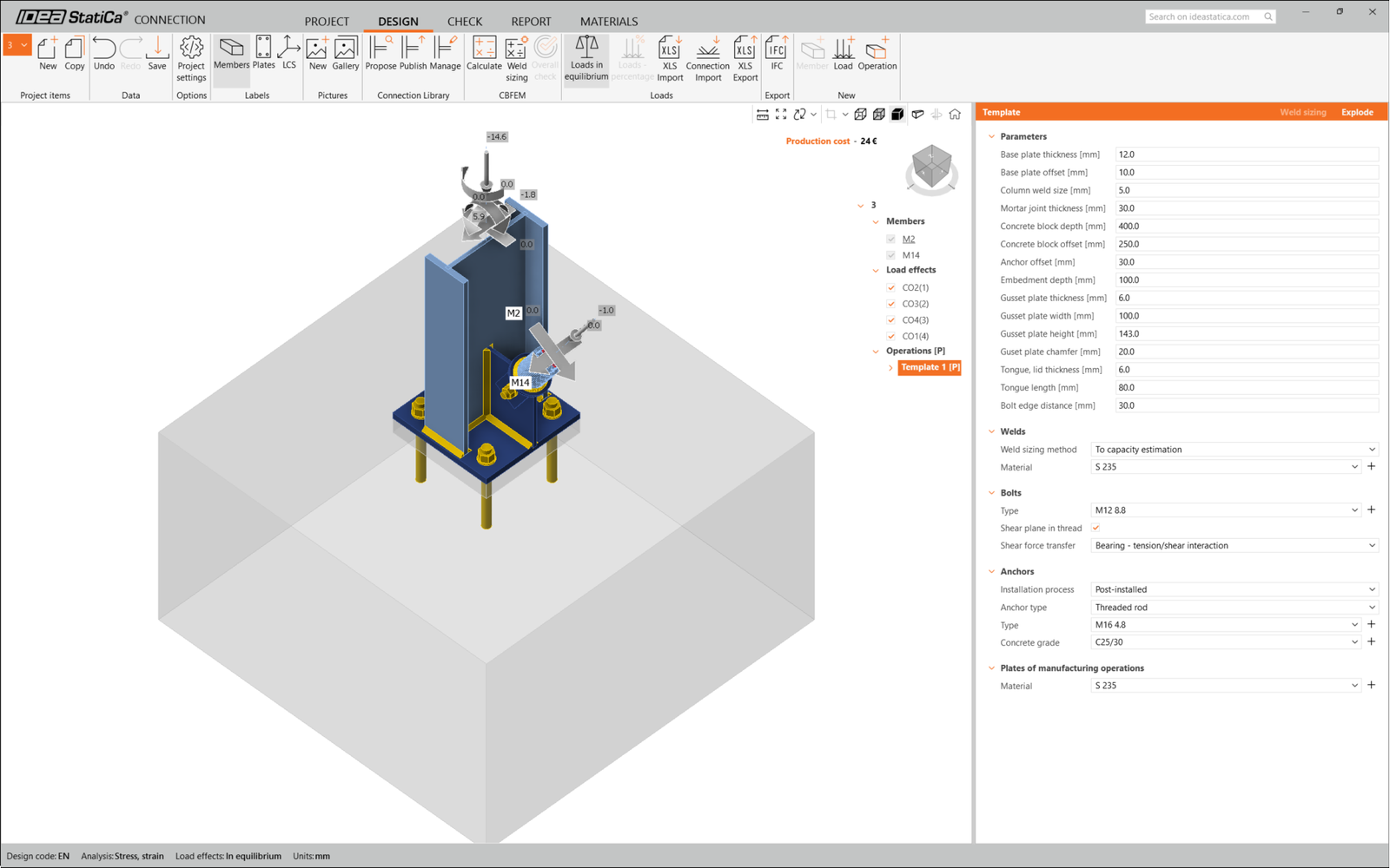
That completes the design of the connection for the column base plate with a diagonal brace.
Code-check and Report
Now run a code-check using the Calculate icon in the CBFEM panel from the top ribbon.
Within IDEA StatiCa Connection, you can carry out many different types of analysis and code-checks. For more information, please see here.

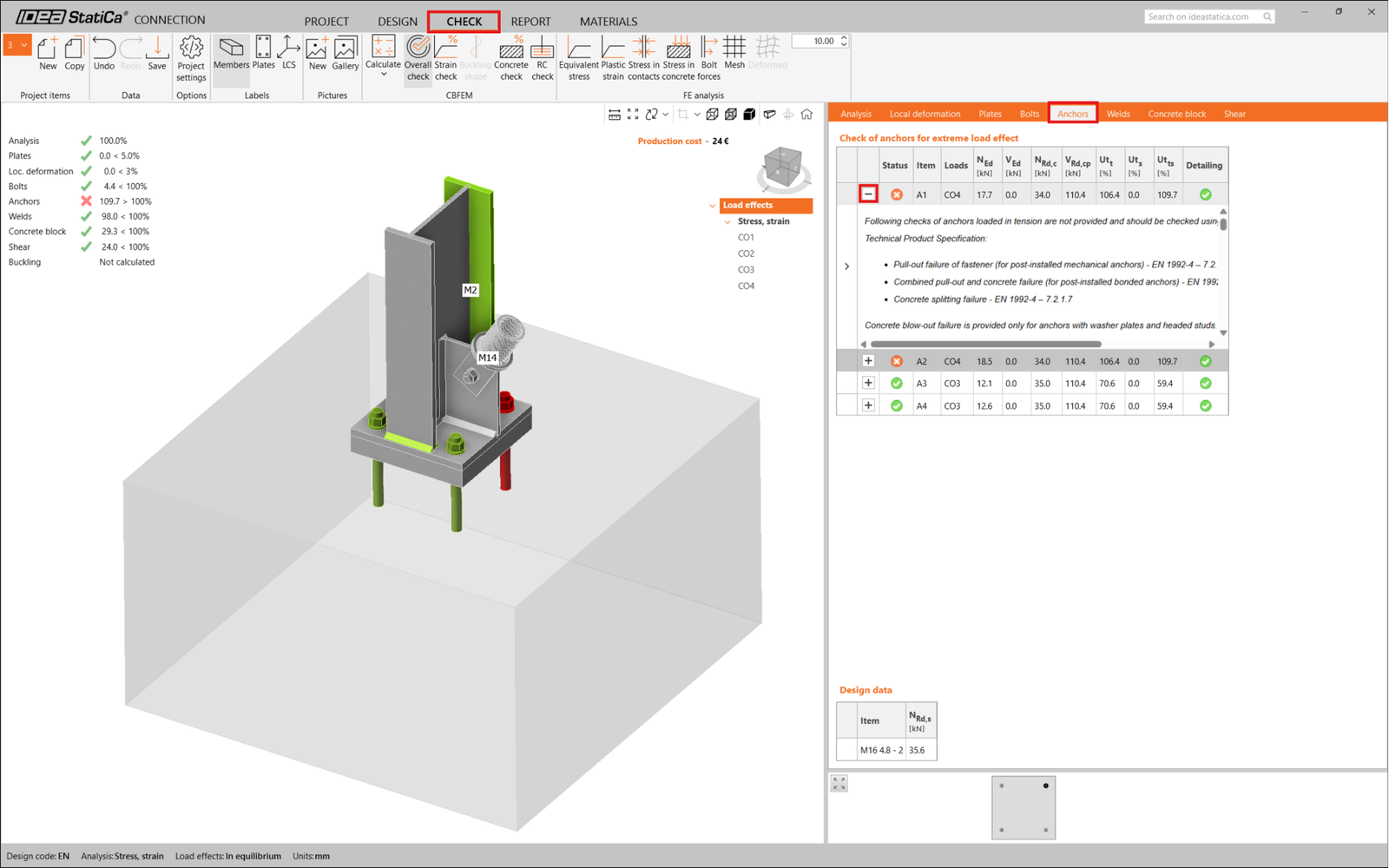
The results might not be acceptable. In this case, the anchors fail because of their low design capacity.
You can go to the Check tab to review the results and take a closer look at the anchors by expanding the calculation using the '+' symbol. You can see that the anchors are failing in tension in the concrete block.
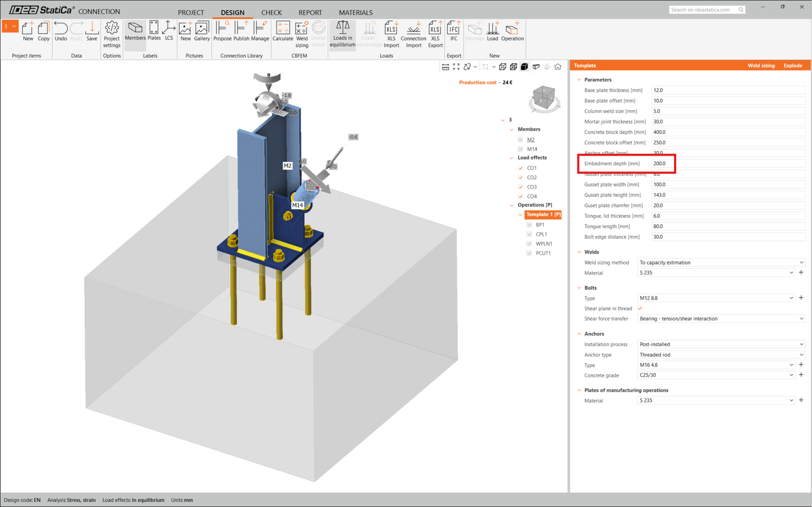
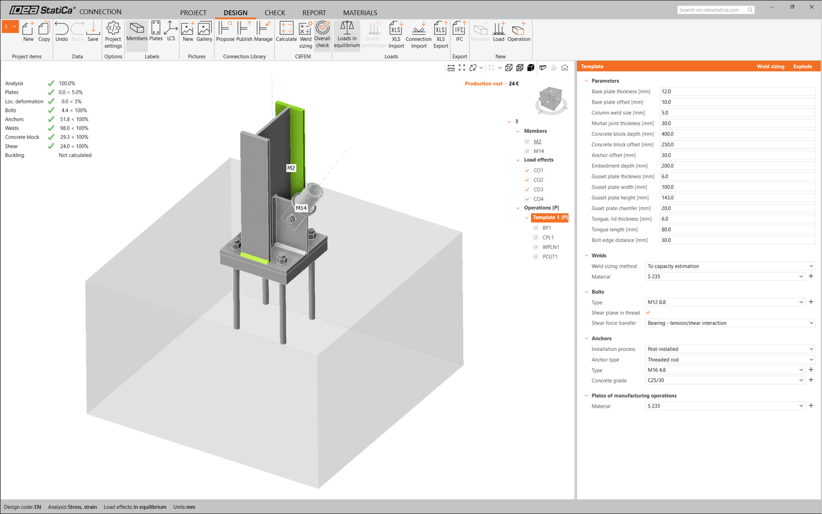
We must optimize the design to find the passing solution. Go back to the Design tab, click on the operation, and change the Anchoring length to 200 mm. Then run the analysis and code-check again.
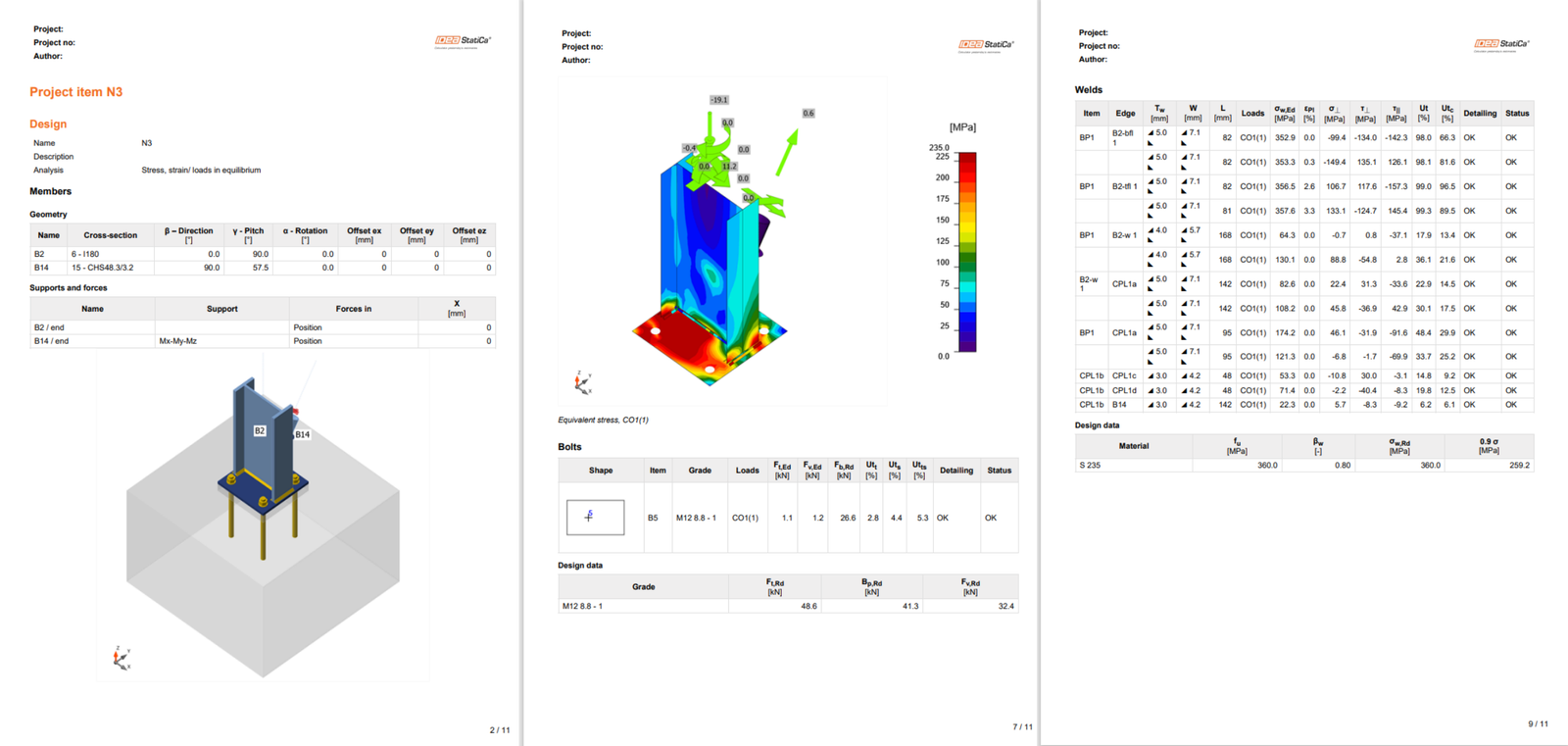
Once the code-check is finished in the Report tab, you can create the report containing results and diagrams for your connection model.
The report can be printed or saved in several formats. For more information, please see here.
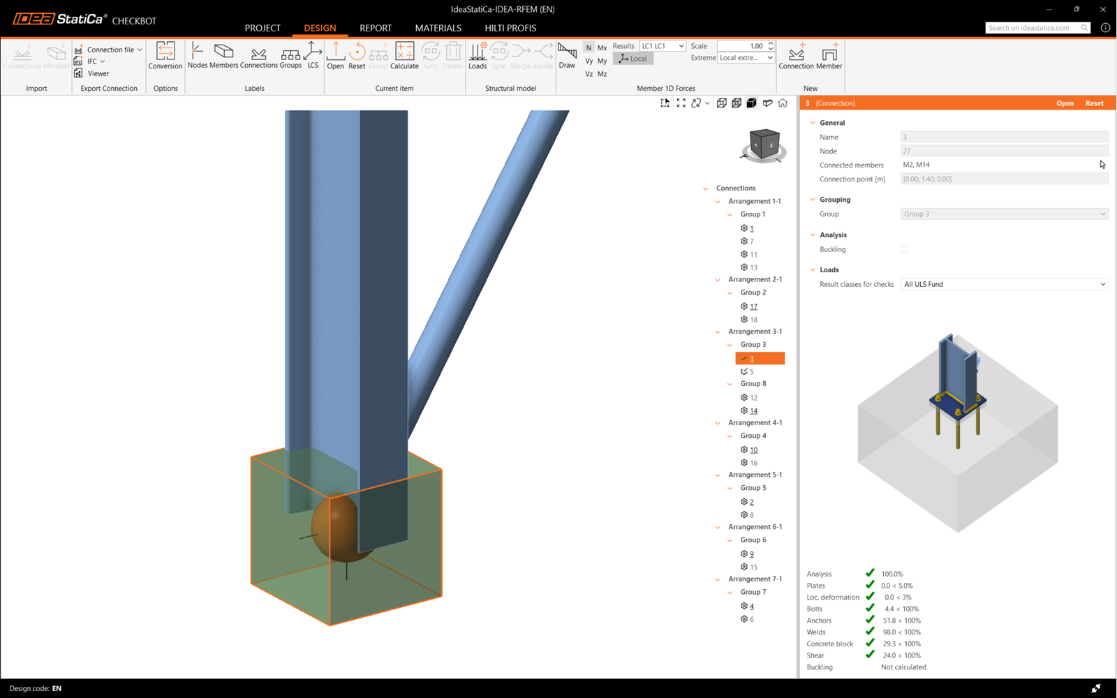
Save this connection and switch back to the Checkbot window (you can keep the Connection window open).
In Checkbot, you will see a green tick next to the connection and the node box filled with green color. This means that the connection has passed all code-checks. In the Connection panel, you can also see a representation of the connection and a summary of the code-check results.
In the example below, you can see that only one connection has passed the respective code-check while the remaining connections have yet to be designed.
You can continue with the design of other connections, either one by one or using the bulk workflows.
Sometimes, there are changes to your FEA model, such as different member cross-section or increased load. These can be synchronized between Checkbot and the FEA model.
There are two possible alternatives:
- Synchronize the Current item (if one or more joints are selected)
- Synchronize the whole imported Structural model
To test this feature, you can change a member cross-section in your FEA application. Remember to re-analyze the FEA model to synchronize fresh results as well.
In Checkbot, select the designed connections (there may be more than one) and from the Current item panel select Sync.

The Checkbot project will be updated. The previously finished connection design is preserved, but the code-checks will be invalidated. You can see that the column is now updated - matching the change in the FEA model.
Simply code-check the highlighted connections again by selecting Calculate from the Current item panel.
If the connections do not give the desired results, then you can open them again to optimize the design (i.e. strengthen if they fail the code-check or lighten if the utilization is too low).
Bigger changes in the FEA model might require synchronization of the whole structural model in Checkbot, instead of just the current item.

Please note that newly added members or loads can not be synchronized, and a new Checkbot project has to be created.
You have successfully linked Robot Structural Analysis with IDEA StatiCa Connection via Checkbot.
Learn how to use IDEA StatiCa effectively with our self-paced e-learning courses
Start learning