Key principles of
IDEA StatiCa Connection

Introduction

IDEA StatiCa Connection is a Component-Based Finite Element Method (CBFEM) design software intended for use by qualified structural engineers familiar with steel connection design. It relies on the users’ understanding of the engineering principles to simulate each joint correctly and interpret the resulting behavior following the FE analysis. As such, it is not intended to replace the user’s engineering knowledge, but to enhance their design capabilities by leveraging the underlying CBFEM engine.

This guide summarises some key elements of the software and is advised to be read by all users of IDEA StatiCa. By doing so, the user will avoid common mistakes that can potentially lead to erroneous results. Moreover, the online sources in the Support Center are constantly updated with new information about the use and principles of using the software. Last, but not least, we strongly advise that you read the theoretical background and its national appendixes as well.

IDEA StatiCa has been developed to model & design steel connections. In this respect, the connection must feature a single identifiable node where all members converge, no matter how complex this connection can be. Please bear in mind that small eccentricities of some members in relation to the node are taken into account by the Finite Element model and do not create any issues to the fictional node concept.

On the other hand, if more than one node can be identified in the model, then this can probably be classified as a structure and the approach followed by IDEA StatiCa might be inappropriate and lead to erroneous results.

The Engineer must use his/her engineering judgment to identify if a connection can be considered as one or more nodes and use the appropriate approach.

As a general rule, the node in IDEA StatiCa must include only the members that are included in the global analysis software, as the forces from the analysis will include only forces for these members. Of course, this is subject to engineering judgment and may vary from case to case.

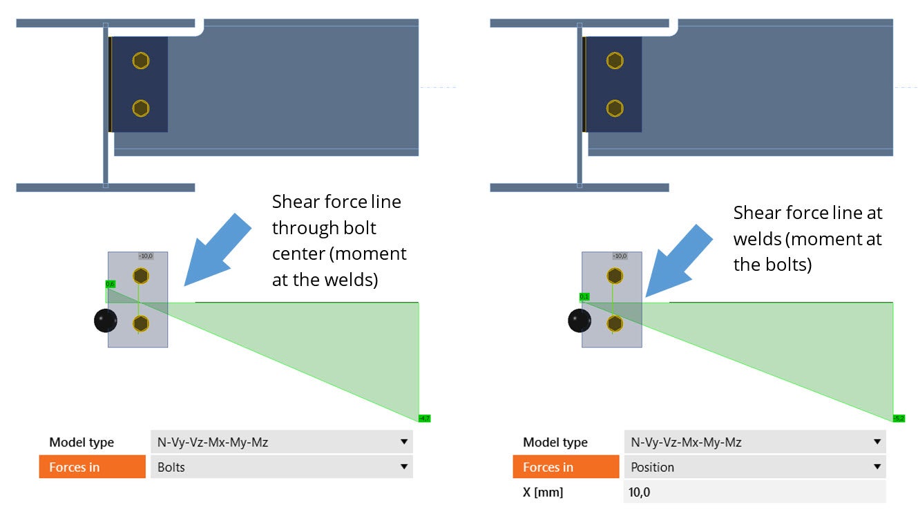
Load effects are defined at the fictional node by default. The user is free to modify the location of the load definition on a member-by-member basis, though. This is something that is a requirement for some cases either from the code (e.g. AISC or SCI fin plate design) or the design specification.

Before using this feature, the user must be aware that different load positions produce different results.

It is common practice for consultants to distribute loads for connection design in the form of loading tables from envelope results, meaning that stress components are non-coexistent.

These loads create an unrealistic stress field. In our solution, this unrealistic stress state is reflected on the model and can potentially lead to failures.

Please note, that this is not a peculiarity of IDEA StatiCa, as such stress states would produce failures in the original global design model if these maximum stress components were applied simultaneously. This problem is exacerbated by the number of connecting members.

To avoid this situation, it is strongly advised to use more than one combination for your designs, originating from the original global design model. It is known that results for each combination are in equilibrium around nodes.

The use of our BIM links makes the transition from the global model to connection design simple and error-proof.

Furthermore, IDEA StatiCa offers a very easy way to identify any unbalanced forces in your model, by enabling the Loads in Equilibrium button. These are the forces that will be balanced by the reactions of the members that are defined as bearing.

The sign of moments does not follow the classic statics convention. Moments follow the right-hand rule around the local axis of the member.

To display the local axis of a member, you should activate the LCS button in the Labels ribbon pane.

To define a positive moment around an axis, the user must point with his right thumb to the positive side of this axis. Then the curl of the fingers represents a rotation that reflects the positive moment around this axis.

Please note that BIM links take care of the required transformations automatically during load transfer from analysis software.

IDEA StatiCa allows the definition of different Model type options in members, with each one influencing what type of constraint will be applied at the member end (with N-Vy-Vz-Mx-My-Mz being a free/unconstrained end). In essence, it is used to ensure that the applied loading corresponds to the global model behavior.

For example, if a bracing member is expected to carry axial and shear loads but no moment then using an unconstrained model would not be adequate since the bracing member would develop a moment along its length. This can be prevented by using an N-Vy-Vz model, where the constraints themselves will resist the moment (which will be shown as Nonconformity under the Check -> Analysis tab). These constraints can also be used to ensure stability in a given model by removing some degrees of freedom. A key example of this is a single bolt bracing connection, where the bracing would be free to rotate about the bolt axis. In this case, using a suitable model type prevents the development of a mechanism.

In general, if the value of the forces/moments being resisted exceeds the applied loading significantly (subject to the designer's judgment), then this could be an indication that the chosen Model type may not be appropriate for the joint and could lead to a nonconservative design. In those cases, it is best to select an alternate model type that corresponds to the loading/support conditions expected or use the unconstrained N-Vy-Vz-Mx-My-Mz model.

The model type choice is generally subject to the designer's judgment, as the constraints required will most often depend on the project specifications and the loading conditions that must be simulated in the model.

Example of a single bolt bracing connection where the model type needs to be N-Vy-Vz, to prevent a mechanism


Although it is possible that for stocky connections buckling analysis may not be critical, it is considered an integral part of the CBFEM method. As such, it is highly recommended to perform buckling analysis after the standard Stress/Strain analysis, to ensure that its limits (see our theoretical background), are respected, and to prove that the strength predicted from the stress-strain analysis can be fully developed.

Additionally, buckling of connection components can influence the stability of the whole structure. In this case, we can say that the type of buckling mode is global. Otherwise, the buckling mode is called local.

It is very important to point out, that different critical factor lower limits (αcr, limit) are applicable for different types of buckling modes. For local buckling modes, a critical factor lower limit of 3 can be adopted, while for global buckling modes, a lower limit of 15 should be adopted (for detailed information see section 4.9 of our Eurocode theoretical background part).

Unfortunately, the type of buckling shape is subject to engineering judgment and cannot be decided by the software. It is the responsibility of the user to decide which type of buckling applies to his model by looking at the deformed buckling shapes.

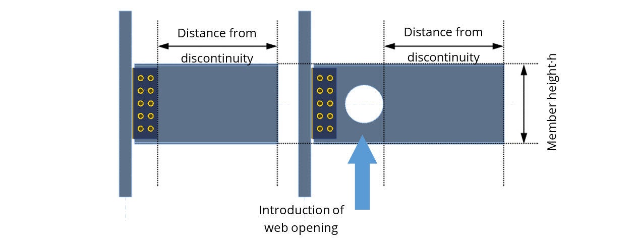
When we add a member to the model, its length is calculated automatically by the software based on the height of the cross-section. The calculation algorithm is part of the CBFEM method and is calibrated after numerical and experimental results.

The calculated member length ensures that proper stress diffusion will take place in accordance with the CBFEM methodology.

In case an element or a modification (bolt holes, notches, openings, etc) is added to this member the software will adjust the overall length accordingly in order to maintain a distance from the discontinuity.

However, the software allows the change of the default factor for the member length calculation, through the “Code setup” settings, which then influences the overall length. Users are strongly advised to leave this value as default, as such changes can influence the results significantly. All our verifications were performed with the default settings.

In rare cases, the default values of this setting may lead to a failure that would not otherwise occur. Examples of rare scenarios might be 1. overly deep beams (e.g. 1.5+ m.) leading to excessive distance from the nearest discontinuity or, 2. high localized shear force applied on a short-length section (e.g. a short console holding crane runway girder), which IDEA StatiCa would, by default, model longer than in reality. Both cases would result in high bending at the loaded end.

It is for this reason that this setting is available, to provide experienced users some flexibility when dealing with these rare cases where a reduced length might be necessary.

In such cases, where it is absolutely clear that the issue is due to the member length alone, the user would need to conduct a study to examine the impact of any reduction in the member depth/length ratio on the model behavior (stress/strain fields and forces in the various components). Should the output match, a reduction in the parameter may be possible, though this may need to be done in conjunction with the mesh settings in some models.

In other words, if the user decides to modify this setting, he/she must be able to adequately justify this by referring to output from an associated study demonstrating that the reduction has not influenced the output in the joint components.

For this reason, we recommend getting in touch with our support team before modifying any of these critical parameters.

Example study demonstrating a reduction in member length/depth ratio without significant impact on stress field and component loading.

It is important to know that different codes use different conventions for the weld definition. The American code, for example, uses leg lengths while Eurocode uses throat thicknesses for the calculation. This convention is respected throughout the whole project, including the report output and drawings.

Therefore, it is the user’s responsibility to adjust these weld sizes when required, in order to communicate them with third parties (e.g. fabricators) that use different conventions.

IDEA StatiCa Connection is a tool primarily dedicated to the assessment of connections of hot-rolled members, which are not significantly affected by buckling. Geometrically linear and material non-linear analysis is performed because of its fast and stable calculation. However, this type of analysis does not account for the loss of stability for each calculation step, as the buckling analysis is linear, while loss of stability requires a geometrically nonlinear analysis to be performed.

If you insist on using IDEA StatiCa Connection for checking thin-walled (cold-formed) member connections, make sure that you are an experienced user of the software and be prepared to carefully apply your engineering judgement to, at least, the following points:

  • Perform linear buckling analysis and carefully evaluate each buckling shape. Please bear in mind that the 5 first calculated buckling shapes might not be enough.
  • Do not rely on the plasticity of thin-walled members, and instead limit the von Mises stress to yield strength or even lower if required.
  • Be aware that the development of local buckling, which is not accounted for in each calculation step, can redistribute internal forces in components differently.
  • Be aware that the stiffness of components may differ, due to different failure modes or their combination.
  • Be aware that presented checks and detailing of components (e.g. bolts, welds) are following code provisions applicable to hot-rolled members. In case relevant code provisions for thin-walled members are different, then the provided checks are not applicable to them.

In IDEA StatiCa Connection, the user is free to model connection topologies that were impossible to be designed previously. The range of provided tools and different types of analysis (buckling, stiffness, etc), offers far greater insight into the behavior of the designed connections than before.

It is the responsibility of the user to learn, understand and apply these tools to his/her designs, especially if he/she decides to deviate from established and tested connection topologies.

It must be clear that IDEA StatiCa is unable to “correct” conceptual design errors. Although it can help to prevent them, with the correct application of the provided toolset.

A conceptually wrong connection with the missing top row seemingly passes all code checks, but with the use of the Deformed shape tool, excessive deformation and concentration of plastic strains is revealed. This can probably cause serviceability problems but without catastrophic failure (such as a fracture).

The calculation method regarding plates is based on non-linear material properties, so it is valid independent of code provisions.

Since in its default state the software uses the stock Eurocode text values, it is the user’s responsibility to verify that the code setup settings are aligned with the desired regional NA provisions.