


Beam IPE 450 to column HEB 340
Type of connection: Single sided haunched joint
Unit system: Metric
Designed acc. to: EN 1993-1-8 and EN 1998-1
Investigated: Plates, bolts
Steel: Grade S355
Bolts: M30 Grade 10.9
The example is taken from R. Landolfo et al. Design of Steel Structures for Buildings in Seismic Areas, ECCS Eurocode Design Manual. Wiley, 2017.
Geometry
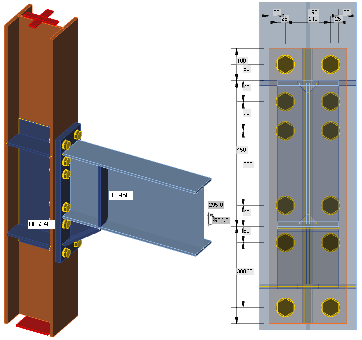
Beam IPE 450 is connected to column HEB 340 via haunched end plate joint. The haunch is under 35° with the web and flange thicknesses of 9.4 mm and 18 mm, respectively. The height of the haunch is 178 mm and the length is 250 mm. The column is stiffened by continuous plates with the thickness of 15 mm and by web doublers from both sides with the thickness of 10 mm each. The height of the doublers is the same as the height of the end plate. The end plate has the thickness of 35 mm.
Applied load
The joint is loaded by the probable bending moment at the formation of plastic hinge in the beam MEd = γsh ⋅ fy,ov ⋅ Wpl and corresponding shear load VEd = 2 ⋅ MEd / Lh, where:
- γsh = 1.2 – strain-hardening factor
- fy,ov = γov ⋅ fyk = 1.25 ⋅ 355 = 443.75 MPa – probable yield strength of the beam
- γov = 1.25 – overstrength factor
- fyk = 355 MPa – characteristic yield strength
- Lh = 6 150 mm – distance between plastic hinges on the beam
The position of the load in the beam is set to the expected position of plastic hinge.

Manual calculation
The components of the connection are loaded by a bending moment at the column face, i.e. Mj,Ed = 981.5 kNm.
The plastic bending resistance of the haunched cross-section: 955.6 kNm – Failed
Column web panel in shear: Loaded by shear force Vwp,Ed = 1581.2 kN, component resistance Vwp,Rd = 1631.5 kN – OK
T-stubs of the end plate for hogging bending moment (only 3 furthest bolt rows are taken into account): MT,Rd = 1018.8 kNm – OK
T-stubs of the end plate for sagging bending moment (only 3 furthest bolt rows are taken into account): MT,Rd = 1080.6 kNm – OK
T-stubs of the column flange for hogging bending moment (only 3 furthest bolt rows are taken into account): MT,Rd = 876.1 kNm – Failed
T-stubs of the column flange for sagging bending moment (only 3 furthest bolt rows are taken into account): MT,Rd = 929.2 kNm – Failed
The connection resistance for hogging bending moment is Mj,Rd = 876.1 kNm and for sagging bending moment is Mj,Rd = 929.2 kNm.
Moment at the column face without the overstrength and strain-hardening factors for the beam: MEd = 654.3 kNm, corresponding shear force VEd = 196.5 kNm. All component checks pass for this load.
The macrocomponents can be classified:
- column web panel – strong
- connection – balanced
Results of IDEA StatiCa
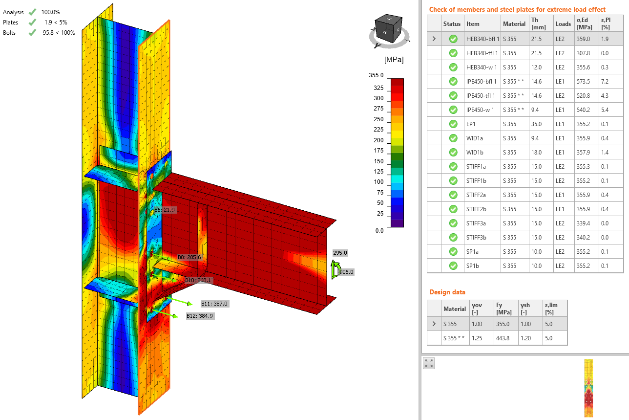
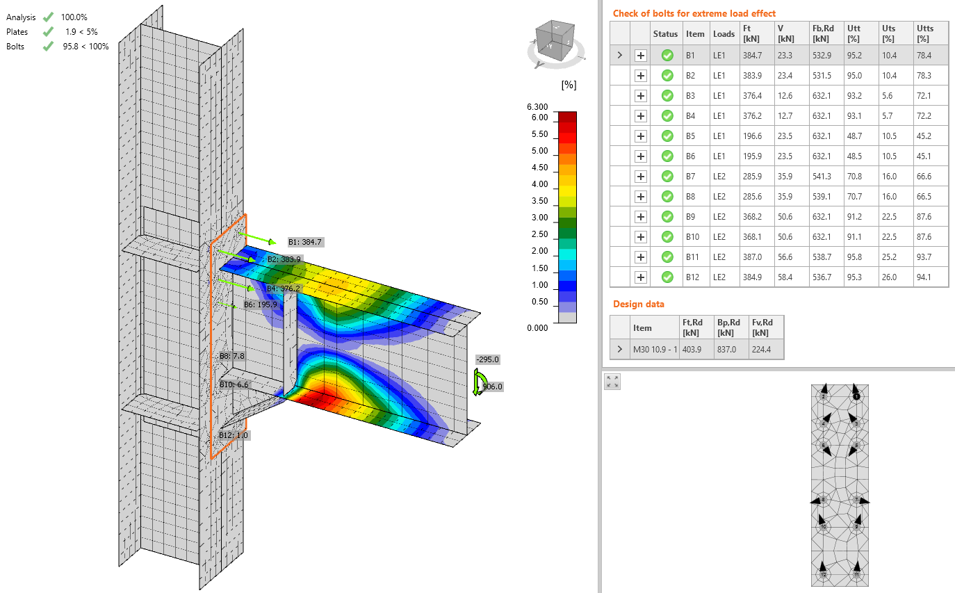
All the components and strain checks on non-dissipative plates pass and thus the macrocomponents can be classified as:
- column web panel: strong
- connection: strong
To determine the maximum load resistance in IDEA Connection, the strain-hardening was iteratively increased alongside with the applied load until the checks failed. The load resistance of this connection is 1 016 kNm at the column face and the corresponding shear force 305 kN.
Comparison
The manual calculation according to Component method (EN 1993-1-8) determines the bending resistance of the connection Mj,Rd = 876.1 kNm with the assumptions of axis of rotation at the middle of the haunch height and only three furthest rows contributing to the bending resistance. The connection is therefore balanced.
IDEA Connection uses Component based finite element method and determines the bending resistance at the column face Mj,Rd = 1 016 kNm. The difference is 15 % compared to the manual calculation. The connection according to CBFEM method is strong.
Welds
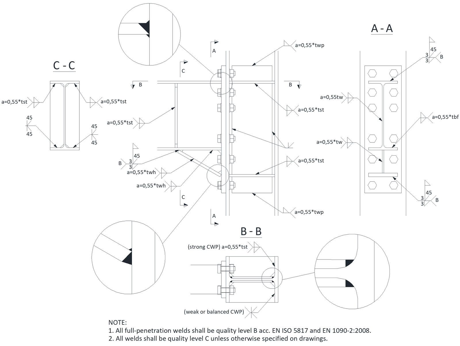
The welds are not checked because the detailing of welds is prescribed according to Equaljoints (R. Landolfo et al. European pre-QUALified steel JOINTS – EQUALJOINTS, Final report, 2016). In IDEA project, all welds are set as butt welds.
Beam IPE 360 to column HEB 280
Type of connection: Single sided haunched joint
Unit system: Metric
Designed acc. to: EN 1993-1-8 and EN 1998-1
Investigated: Plates, bolts
Steel: Grade S355
Bolts: M27 Grade 10.9
The example is taken from EQUALJOINTS example No. 264: https://itunes.apple.com/us/app/equal-joints/id1406825195?mt=8
Geometry
Beam IPE 360 is connected to column HEB 280 via haunched end plate joint. The haunch is under 45° with the web and flange thicknesses of 8 mm and 12.7 mm, respectively. The height and length of the haunch are 200 mm. The column is stiffened by continuous plates with the thickness of 12 mm and by web doublers from both sides with the thickness of 10 mm each. The height of the doublers is the same as the height of the end plate. The end plate has the thickness of 25 mm.
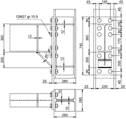
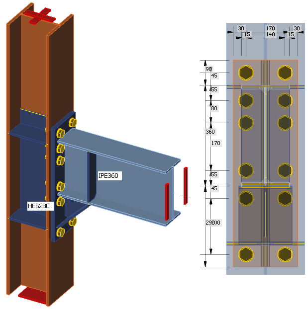
Applied load
The joint is loaded by the probable bending moment at the formation of plastic hinge in the beam MEd = γsh ⋅ fy,ov ⋅ Wpl and corresponding shear load VEd = 2 ⋅ MEd / Lh, where:
- γsh = 1.2 – strain-hardening factor
- fy,ov = γov ⋅ fyk = 1.25 ⋅ 355 = 443.75 MPa – probable yield strength of the beam
- γov = 1.25 – overstrength factor
- fyk = 355 MPa – characteristic yield strength
- Lh = 7 320 mm – distance between plastic hinges on the beam
The position of the load in the beam is set to the expected position of plastic hinge.

Manual calculation
The components of the connection are loaded by a bending moment at the column face, i.e. Mj,Ed = 572.8 kNm.
The plastic bending resistance of the haunched cross-section: 582.3 kNm – OK
Column web panel in shear: Loaded by shear force Vwp,Ed = 1 034.6 kN, component resistance Vwp,Rd = 1 202.8 kN – OK
T-stubs of the end plate for hogging bending moment (only 3 furthest bolt rows are taken into account): MT,Rd = 573.0 kNm – OK
T-stubs of the end plate for sagging bending moment (only 3 furthest bolt rows are taken into account): MT,Rd = 697.5 kNm – OK
T-stubs of the column flange for hogging bending moment (only 3 furthest bolt rows are taken into account): MT,Rd = 545.4 kNm – Failed
T-stubs of the column flange for sagging bending moment (only 3 furthest bolt rows are taken into account): MT,Rd = 579.5 kNm – Failed
The connection resistance for hogging bending moment is Mj,Rd = 545.4 kNm and for sagging bending moment is Mj,Rd = 579.5 kNm.
Moment at the column face without the overstrength and strain-hardening factors for the beam: MEd = 381.9 kNm, corresponding shear force VEd = 98.9 kNm. All component checks pass for this load.
The macrocomponents can be classified:
- column web panel – strong
- connection – balanced
Results of IDEA StatiCa
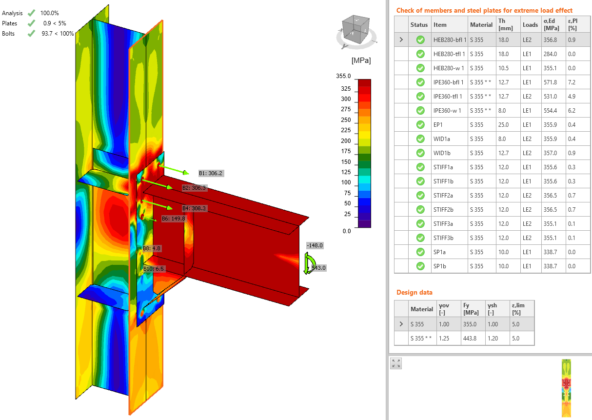
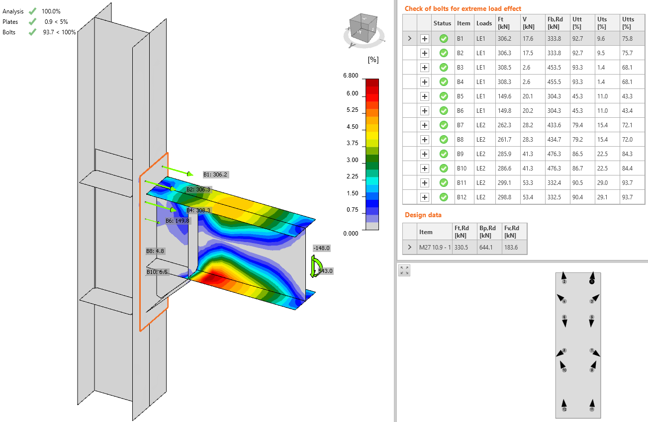
All the components and strain checks on non-dissipative plates pass and thus the macrocomponents can be classified as:
- column web panel: strong
- connection: strong
To determine the maximum load resistance in IDEA Connection, the strain-hardening was iteratively increased alongside with the applied load until the checks failed. The load resistance of this connection is 657.4 kNm at the column face and the corresponding shear force 170.3 kN.
Comparison
The manual calculation according to Component method (EN 1993-1-8) determines the bending resistance of the connection Mj,Rd = 545.4 kNm with the assumptions of axis of rotation at the middle of the haunch height and only three furthest rows contributing to the bending resistance. The connection is therefore balanced.
IDEA Connection uses Component based finite element method and determines the bending resistance at the column face Mj,Rd = 657.4 kNm. The difference is 20 % compared to the manual calculation. Increasing the mesh density slightly reduces the joint resistance. With dense mesh – 24 elements on member's web, the utilization of bolts is 99 % and plastic strain on end plate is 4.1 % at the set load. Therefore, Mj,Ed = 572.8 kNm at column face is very close to the limit resistance. This resistance is 15 % lower than with default mesh density and 5 % higher than according to manual calculation. It is recommended to increase mesh density for long end plates. The connection according to CBFEM method is strong.
Beam IPE 600 to column HEB 500
Type of connection: Single sided haunched joint
Unit system: Metric
Designed acc. to: EN 1993-1-8 and EN 1998-1
Investigated: Plates, bolts
Steel: Grade S355
Bolts: M36 Grade 10.9
The example is taken from EQUALJOINTS example No. 267: https://itunes.apple.com/us/app/equal-joints/id1406825195?mt=8
Geometry
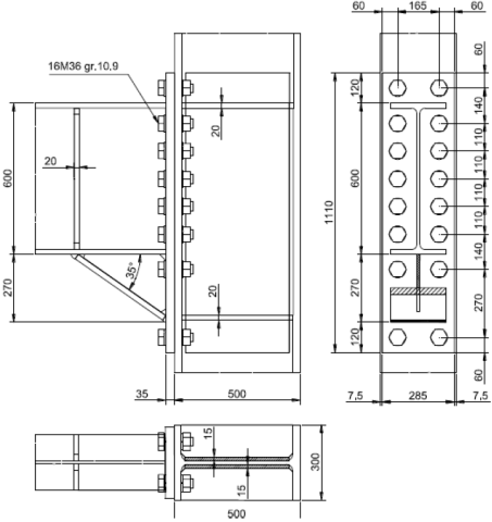
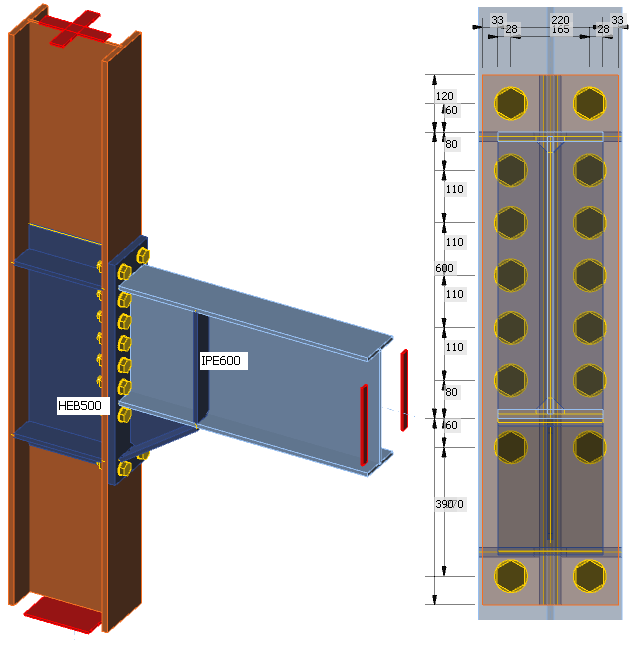
Beam IPE 600 is connected to column HEB 500 via haunched end plate joint. The haunch is under 35° with the web and flange thicknesses of 12 mm and 19 mm, respectively. The height and length of the haunch are 270 mm and 386 mm, respectively. The column is stiffened by continuous plates with the thickness of 20 mm and by web doublers from both sides with the thickness of 15 mm each. The height of the doublers is the same as the height of the end plate. The end plate has the thickness of 35 mm.
Applied load
The joint is loaded by the probable bending moment at the formation of plastic hinge in the beam MEd = γsh ⋅ fy,ov ⋅ Wpl and corresponding shear load VEd = 2 ⋅ MEd / Lh, where:
- γsh = 1.2 – strain-hardening factor
- fy,ov = γov ⋅ fyk = 1.25 ⋅ 355 = 443.75 MPa – probable yield strength of the beam
- γov = 1.25 – overstrength factor
- fyk = 355 MPa – characteristic yield strength
- Lh = 6 658 mm – distance between plastic hinges on the beam
The position of the load in the beam is set to the expected position of plastic hinge.

Manual calculation
The components of the connection are loaded by a bending moment at the column face, i.e. Mj,Ed = 2 105.4 kNm.
The plastic bending resistance of the haunched cross-section: 1 903.3 kNm – Failed
Column web panel in shear: Loaded by shear force Vwp,Ed = 2 446.8 kN, component resistance Vwp,Rd = 2 773.7kN – OK
T-stubs of the end plate for hogging bending moment (only 4 furthest bolt rows are taken into account): MT,Rd = 1 998.9 kNm – Failed
T-stubs of the end plate for sagging bending moment (only 4 furthest bolt rows are taken into account): MT,Rd = 2 317.7 kNm – OK
T-stubs of the column flange for hogging bending moment (only 4 furthest bolt rows are taken into account): MT,Rd = 2 015.1 kNm – Failed
T-stubs of the column flange for sagging bending moment (only 4 furthest bolt rows are taken into account): MT,Rd = 2 106.5 kNm – OK
The connection resistance for hogging bending moment is Mj,Rd = 1 903.3 kNm and for sagging bending moment is Mj,Rd = 1 903.3 kNm. The bending resistance of the haunched cross-section is decisive. The overstrength factor is used for the whole beam and thus, the increased yield strength could be used for the haunched cross-section as well and the bending resistance would be higher. Next weakest components are T-stubs of end plate and column flange. The connection resistance for hogging and sagging bending moment would be Mj,Rd = 1 998.9 kNm Mj,Rd = 2 106.5 kNm, respectively. With this assumption, the connection would be full strength for γsh = 1.1 as suggested by EN 1998-1.
Moment at the column face without the overstrength and strain-hardening factors for the beam: MEd = 1 403.6 kNm, corresponding shear force VEd = 374.3 kNm. All component checks pass for this load.
The macrocomponents can be classified:
- column web panel – strong
- connection – balanced
Results of IDEA StatiCa
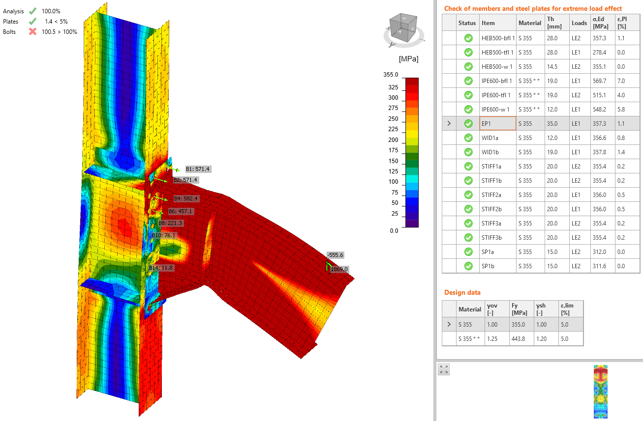
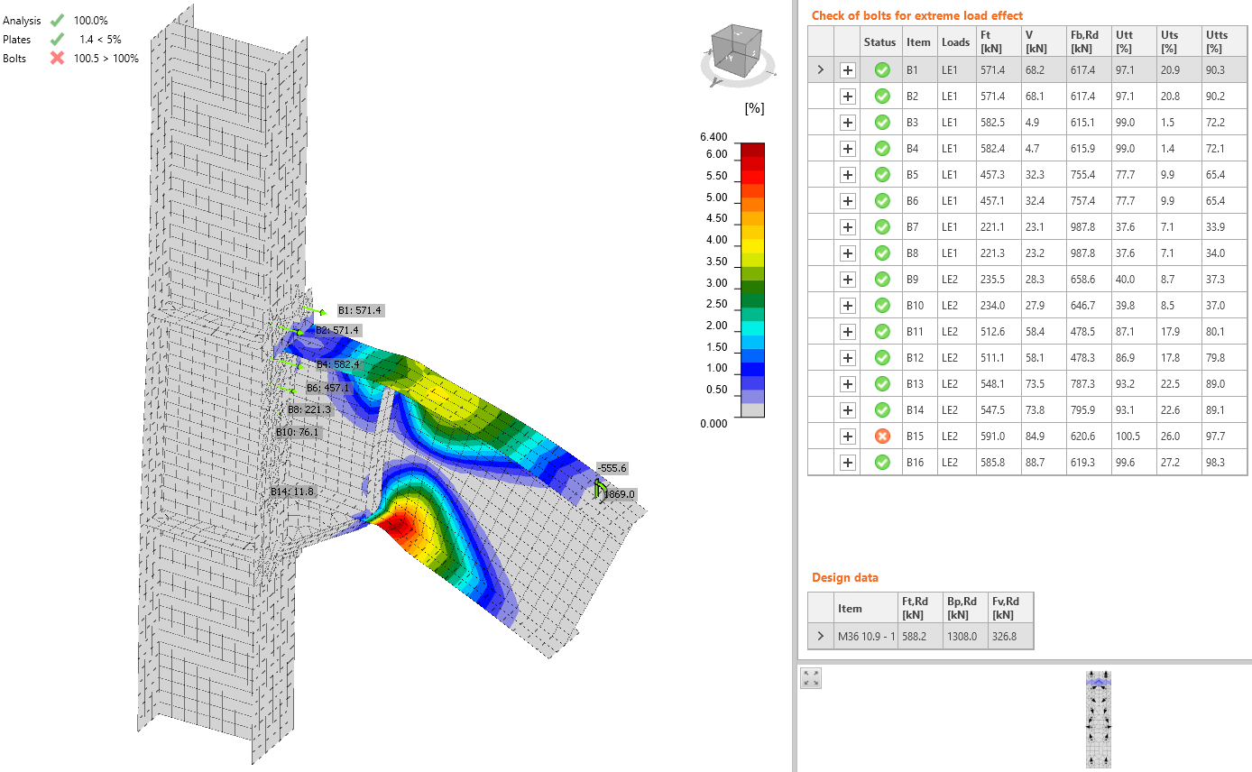
The deformed shape with deformation scale 5 is shown and the plastic hinge is clearly visible. The bolts are just slightly over 100 % utilization and the maximum plastic strain of most stressed plates are 1.4, 1.1, and 1.1 for the flange of the widener, the end plate, and the column flange, respectively. The resistance is expected very slightly below the set loads. The macrocomponents can be classified as:
- column web panel: strong
- connection: balanced
Comparison
The manual calculation according to Component method (EN 1993-1-8) determines the bending resistance of the connection Mj,Rd = 1 903.3 kNm with the assumptions of axis of rotation at the middle of the haunch height and only three furthest rows contributing to the bending resistance. The connection is therefore balanced. Considering the increase in the yield strength of the beam at the end plate face, the resistance of the governing component would be higher. Next governing component is the end plate with Mj,Rd = 1 998.9 kNm.
IDEA Connection uses Component based finite element method and determines the bending resistance at the column face Mj,Rd = 2 100 kNm. The difference is 5 % compared to the manual calculation. Increasing the mesh density slightly reduces the joint resistance. With dense mesh – 16 elements on member's web, the resistance drops by only 2 %. The connection according to CBFEM is balanced.