Stiffness analysis and deformation capacity of steel joints
Joints are classified according to stiffness to rigid, semirigid, and pinned. The engineer should ensure the stiffness of the joint confirms the stiffness set in the CAE software.
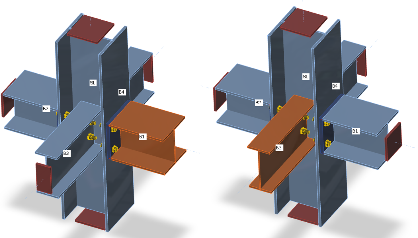
The CBFEM method analyzes the stiffness of connection of individual joint members. For the proper stiffness analysis, a separate analysis model must be created for each analyzed member. Then, the stiffness analysis is not influenced by the stiffness of other members of joint but only by the node itself and the construction of the connection of the analyzed member. Whereas the bearing member is supported for the strength analysis (member SL in the figure below), all members except the analyzed one are supported by the stiffness analysis (see two figures below for stiffness analysis of members B1 and B3). The exception is the column base where supports are provided by the concrete foundation, only the analyzed member is loaded, and other members have restrains only according to their model type.
Supports on members for strength analysis
| Supports on members for stiffness analysis of member B1 | Supports on members for stiffness analysis of member B3 |
Loads can be applied only to the analyzed member. If bending moment, My, is defined, the rotational stiffness about the y-axis is analyzed. If bending moment Mz is defined, the rotational stiffness about the z-axis is analyzed. If axial force N is defined, the axial stiffness of the connection is analyzed.
The program generates a complete diagram automatically, it is directly displayed in GUI and can be added to the output report. Rotational or axial stiffness can be studied for specific design loads. IDEA StatiCa Connection can also deal with the interaction of the other internal forces.
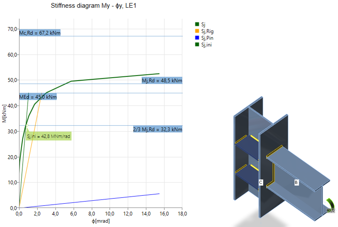
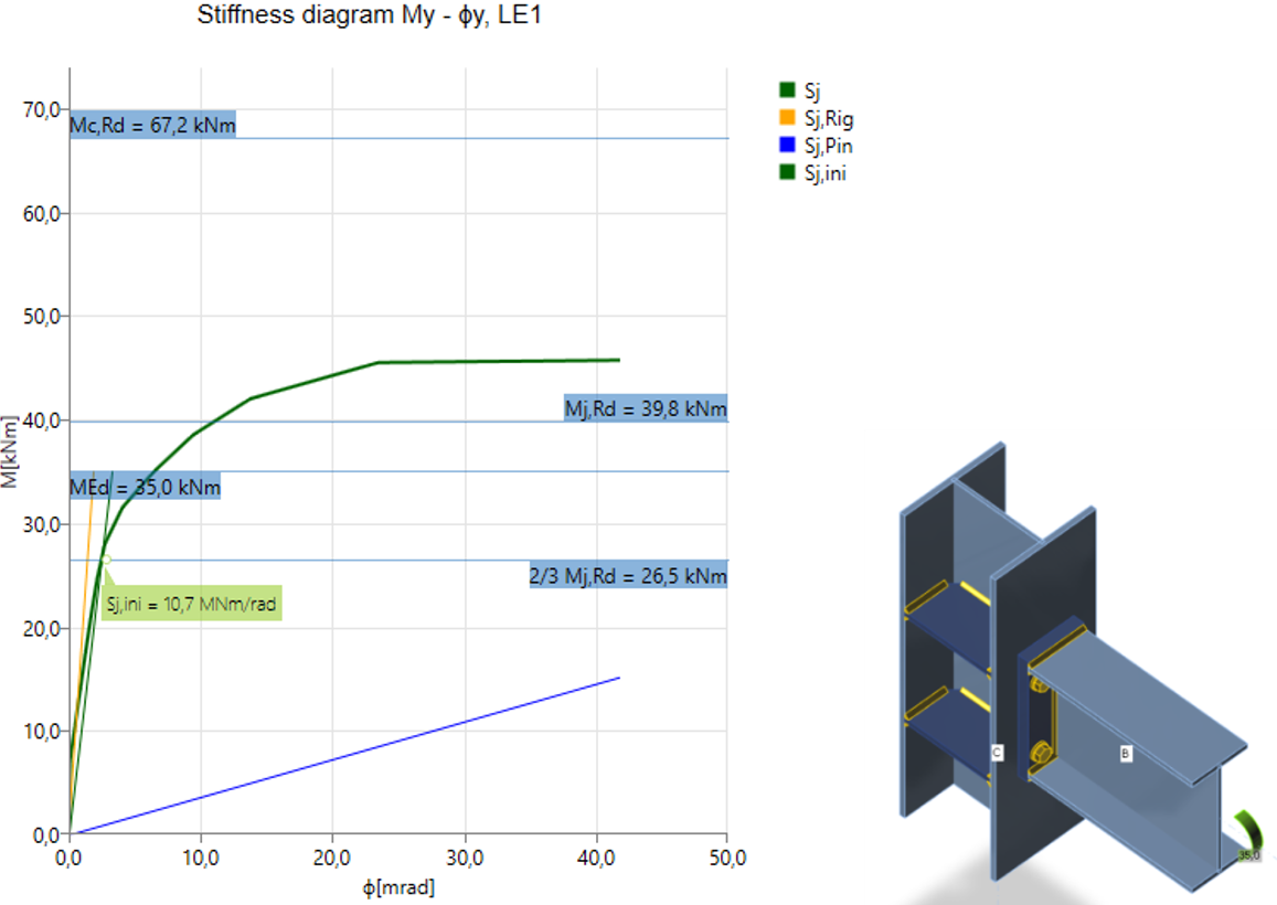
Diagram shows:
- Level of design load MEd
- Limit value of capacity of connection for 5% equivalent strain Mj,Rd; limit for plastic strain may be changed in Code setup
- The limit value of capacity of connected member (useful also for seismic design) Mc,Rd
- 2/3 of limit capacity for calculation of initial stiffness
- Value of initial stiffness Sj,ini
- Value of secant stiffness Sjs
- Limits for the classification of connection – rigid and pinned
- Rotational deformation Φ
- Rotational capacity Φc
Rigid welded connection
Semi-rigid bolted connection
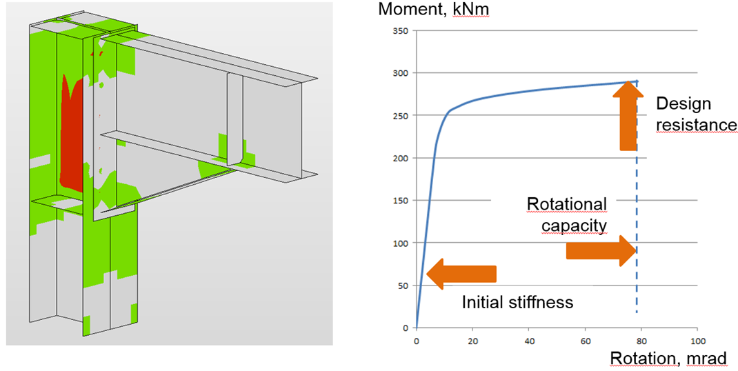
After reaching the 5 % strain in the column web panel in shear, the plastic zones propagate rapidly
The joint is classified according to its stiffness into rigid, semi-rigid, or pinned category according to the relevant code. The theoretical length of the member can be set for the analyzed member:
How are the loads applied?
Only one member is loaded and investigated in the stiffness analysis. The analyzed member may be loaded by:
- Normal force N
- Shear forces Vy and Vz
- Bending moments My and Mz
- Torsion Mx
All load effects are applied simultaneously. If the applied loads are too small, they are all increased by a factor so that the joint resistance is reached. When creating the moment-rotation or load-deformation diagrams, all the load effects are increased in steps proportionally.
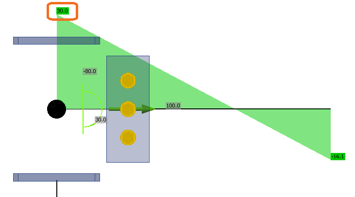
For example, the analyzed member is loaded by:
- Normal force N = 50 kN
- Shear force Vz = -80 kN
- Bending moment My = 30 kNm
The member resistances are:
- Normal resistance NR = 2 111 kN
- Shear resistance Vz,R = 763 kN
- Bending moment resistance My,R = 226 kNm
The loads are multiplied by a factor:
\[ \alpha = \textrm{min} \left \{ \frac{N_R}{N}, \, \frac{M_{y,R}}{M_y}, \, \frac{M_{z,R}}{M_z} \right \} \]
Note that if the shear force is not applied in the node, i.e. it acts on a lever arm, the bending moment is affected. The bending moment in the node, as seen in a wireframe model, is used as a set load.
In this example, the factor is \( \alpha = 7.53 \). Set loads are multiplied and then applied in steps, and the results are plotted in the Stiffness diagram. The applied loads are divided into 12 steps, and when the connection is nearing its resistance, the steps are further refined. The example of the first three steps is in the following table:
| Set loads | Applied loads | First step | Second step | Third step | |
| 100% | 8.33% | 16.67% | 25.00% | ||
| N | 50 | 377 | 31 | 63 | 94 |
| Vy | 0 | 0 | 0 | 0 | 0 |
| Vz | -80 | -603 | -50 | -100 | -151 |
| Mx | 0 | 0 | 0 | 0 | 0 |
| My | 30 | 226 | 19 | 38 | 57 |
| Mz | 0 | 0 | 0 | 0 | 0 |
Deformation capacity
The deformation capacity/ductility δCd belongs with the resistance and the stiffness to the three basic parameters describing the behavior of connections. In moment-resistant connections, the ductility is achieved by a sufficient rotation capacity φCd. The deformation/rotation capacity is calculated for each connection in the joint separately.
The software estimates the deformation capacity as a point where one of the following conditions is achieved:
- Bolt or anchor resistance in tension, shear, or tension/shear interaction is reached
- Weld resistance is reached
- Plastic strain in plates is 15 %
The estimation of the rotation capacity is important in connections exposed to seismic, see Gioncu and Mazzolani (2002) and Grecea (2004) and extreme loading, see Sherbourne and Bahaari (1994 and 1996). The deformation capacity of components has been studied from the end of the last century (Foley and Vinnakota, 1995). Faella et al. (2000) carried out tests on T-stubs and derived the analytical expressions for the deformation capacity. Kuhlmann and Kuhnemund (2000) performed tests on the column web subjected to transverse compression at different levels of compression axial force in the column. Da Silva et al. (2002) predicted deformation capacity at different levels of axial force in the connected beam. Based on the test results combined with FE analysis, deformation capacities are established for the basic components by analytical models by Beg et al. (2004). In the work, components are represented by non-linear springs and appropriately combined in order to determine the rotation capacity of the joint for the end-plate connections, with an extended or flush end-plate and welded connections. For these connections, the most important components that may significantly contribute to the rotation capacity were recognized as the web in compression, column web in tension, column web in shear, column flange in bending, and end-plate in bending. Components related to the column web are relevant only when there are no stiffeners in the column that resist compression, tension, or shear forces. The presence of a stiffener eliminates the corresponding component, and its contribution to the rotation capacity of the joint can be therefore neglected. End-plates and column flanges are important only for end-plate connections where the components act as a T-stub, where also the deformation capacity of the bolts in tension is included. The questions and limits of the deformation capacity of connections of high-strength steel were studied by Girao et al. (2004).


