
IDEA StatiCa Checkbot for Autodesk Advance Steel (BETA)
IDEA StatiCa Checkbot is available for a selected group of testers only. If you want to be one of them, fill in the request form. If you are selected for the application tests, you will receive the plugin installation file via email.
1 How to activate the plugin
- Install the Checkbot for Advance Steel plugin (receive the installation setup separately by email)
- Make sure you are using the supported version of Autodesk Advance Steel (recommended Advance Steel 2021)
- The displayed table will show you the status of the installation.
- Please note that you need an internet connection to work with the Checkbot plug-in.

When you open Autodesk Advance Steel, there is a new tab IDEA StatiCa added to the top ribbon containing the Checkbot command.
2 How to use the plugin
Open the attached project (below this tutorial) in Advance Steel. Then choose IDEA StatiCa in the upper ribbon and open the Checkbot.

In the tab Load You can adjust the increments of internal forces as the load percentage based on the connected member resistance, the default values are recommended.

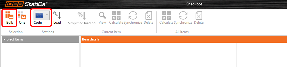
Choose the desired Code and click Bulk to start the selection of the joints for code-check.
Select the joints that you want to code-check and press the spacebar to confirm. There is a check for missing welds, that would add them automatically to the non-connected plates. Click No, since there are no missing welds in this project.

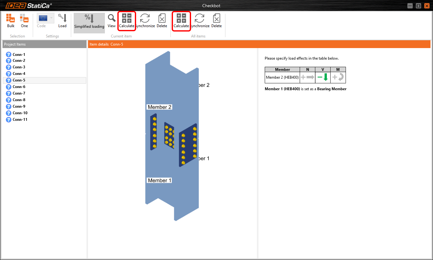
All connections are imported to the Checkbot tab. Select each joint in the list and activate the design load scenario of the simplified loading by clicking on the internal forces symbols. Clicking repeatedly switches the directions of the acting forces. The bearing member is selected automatically.

When you are done with setting the load effects, run the CBFEM cloud analysis with the command Calculate for the selected joint or for all joints at once.
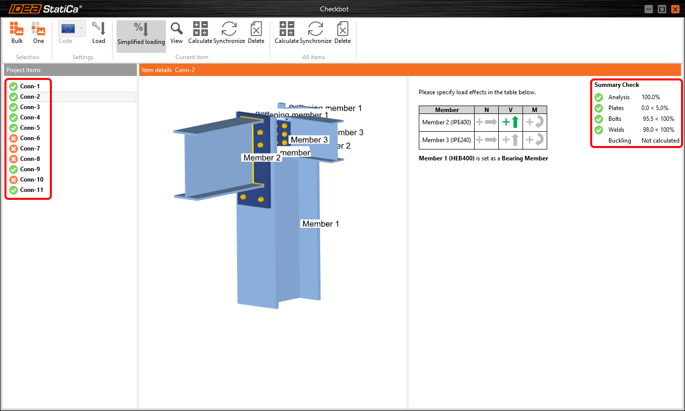
When the analysis is finished, you can browse the overall results of all components, such as plates, bolts, welds, etc.
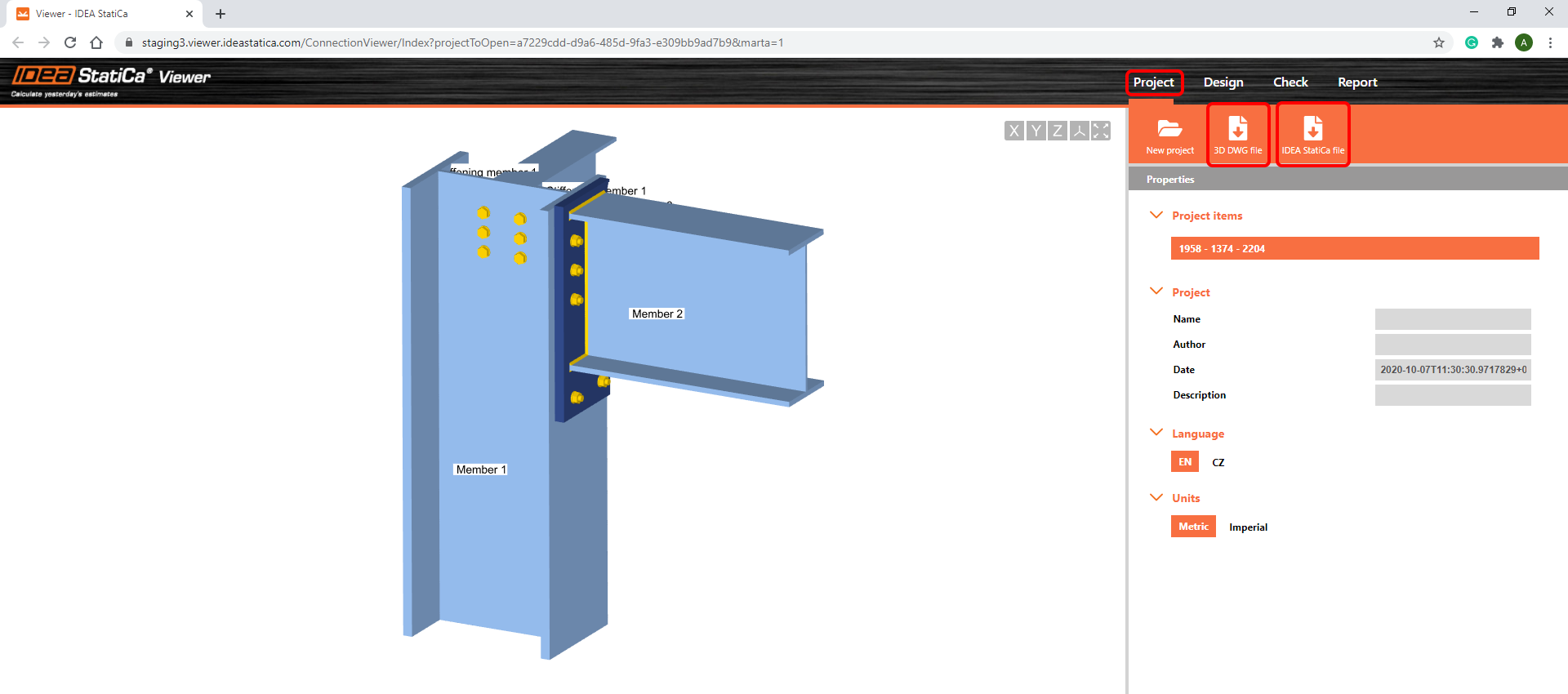
To see the details of the CBFEM analysis and to print out the report, click on the command View to open the connection in the browser application IDEA StatiCa Viewer.

In the Viewer tab Check, you can browse the detailed results e.g. for welds as well as display the stresses and strains in the connection.
NOTE: If you don't see the results here, they haven't been uploaded from the Checkbot. Please click the Calculate button to repeat the analysis in the Viewer.

Finally, go to the Report tab. Here you can modify the content to be printed out in the report. Select it in the list and click Create report. The report is generated and can be printed to PDF or paper with the Print report command.

In the Viewer tab Project, you can also download the IDEA StatiCa file for the desktop application Connection and generate a 3D DWG file of the single joint.
Connections that did not pass the code-checks can be modified in the Advance Steel model, synchronized and recalculated. The Synchronize function updates the model data such as plate thickness, position and amount of bolts, weld size, etc. You can either synchronize and calculate one selected joint or the whole list at once.

Watch the video below to see how to work with the IDEA StatiCa Checkbot.
Known limitations for Checkbot for Autodesk Advance Steel
For now, the Checkbot works for a wide variety of connections/joints. However, please take into account yet unsupported functionality.
Bulk selection
- The bulk selection functionality may not identify all connections properly, or fail to import all relevant entities (plates, bolts, welds). In such cases, please use the One selection instead.
- The Bearing Member is chosen automatically. Currently, the only way to change it is to use the One selection instead, then it will be the first member selected.
- Up to 30 unique load cases can be calculated in parallel, you may start to experience delays in calculation times above this limit.
Viewer
- A connection that has been calculated in the Checkbot and consequently opened in the Viewer requires recalculation, the results are not stored.
- There is no clear indication of the direction of input loads in the Viewer.
Import
- The import of loads directly from the CAD model is not currently supported.
- The following limitations for the general BIM link may apply as well