
Tekla Structures BIM link for the structural design of a steel connection (EN)
1 How to activate the link
- Download and install (as administrator) the latest version of IDEA StatiCa
- Make sure that you are using the supported version of Tekla Structures
IDEA StatiCa automatically integrates the BIM link into your CAD/CAE software during its installation. You can check the status and activate more BIM links for later installed software in the BIM link installer.
Open IDEA StatiCa and navigate to the panel BIM and open the BIM link installer. A notification "Run as administrator" may appear, please confirm with the Yes button.

Select the software to integrate the IDEA StatiCa BIM link into, click the Install button, and check the Installed status.

2 How to use the link
Open the attached project in Tekla Structures. Then choose the IDEA StatiCa tab in the top ribbon. The Code-check manager can be started from the selected ribbon.

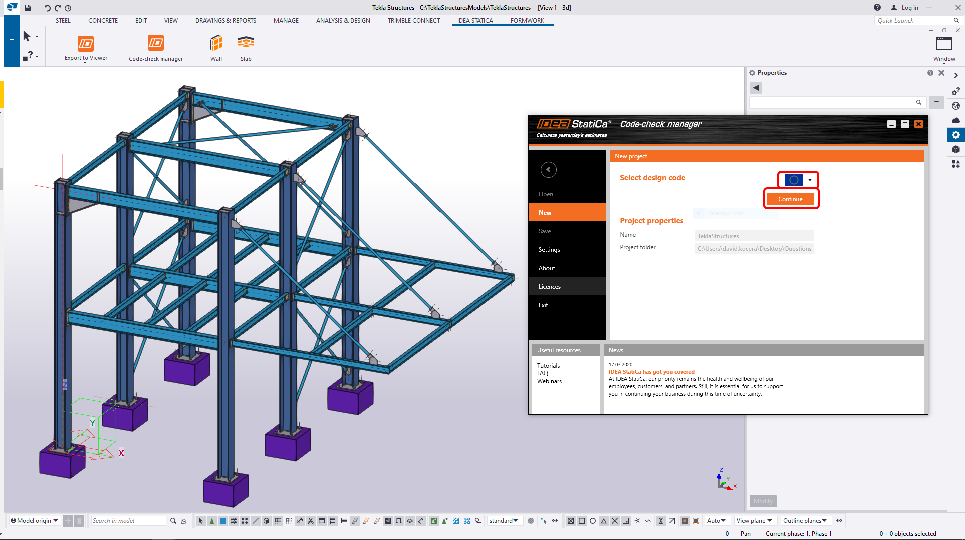
The Code-check manager, the application for BIM imports, automatically appears. You can proceed with selecting the EN code and confirmation with the Continue command to start the BIM import.
The new project was created and you can start with the exports. The first step is the export to the Connection application.

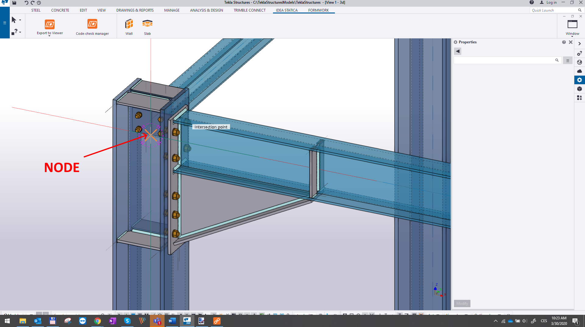
Now the whole joint has to be defined. The application tells us what to do at the bottom command line. In this step, you should choose the node which will be representing the node of the joint. The selection can be confirmed by the spacebar.
In the next step, the members have to be chosen. The first chosen member will be the bearing one. When all members all selected, confirm with the spacebar.

In the end, select all the remaining entities of the connection such as plates, bolts, and welds, and confirm with the spacebar.

After the confirmation automatic data transfer is performed, the Code-check manager imports the connection and creates the item in the list of exported connections. The connection and its components are highlighted in the Tekla Structures window.

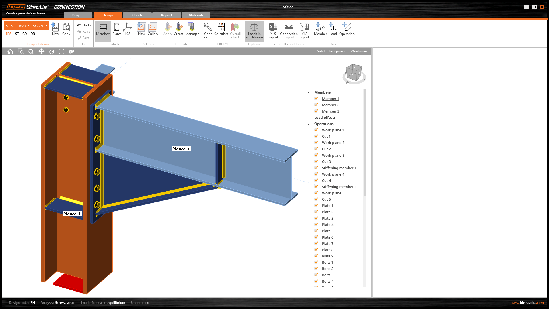
Let's proceed with the Open button in the Code-check manager. In a while, the IDEA StatiCa Connection application window automatically appears with the exported connections. All members, plates, welds, etc. were added automatically.
3 Load effects
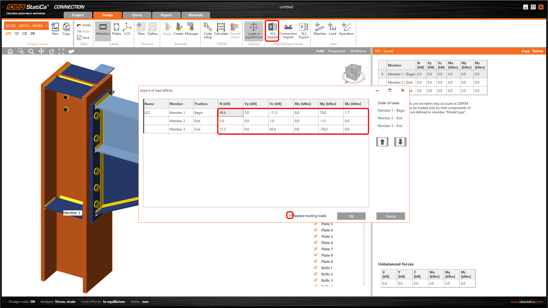
When you import a model from CAD program like Tekla Structures, you need to input the internal forces to load the members. In this example where you have many members, you can easily import the forces from the attached excel sheet.
To import the forces, you can check workflow in the Knowledgebase: How to import load effects from an Excel sheet.
4 Design
If you would like to or it is necessary, you could change whatever you want in IDEA StatiCa (change settings, add some operations, etc.). Regarding our connection, we have finished the design.
5 Calculation and Check
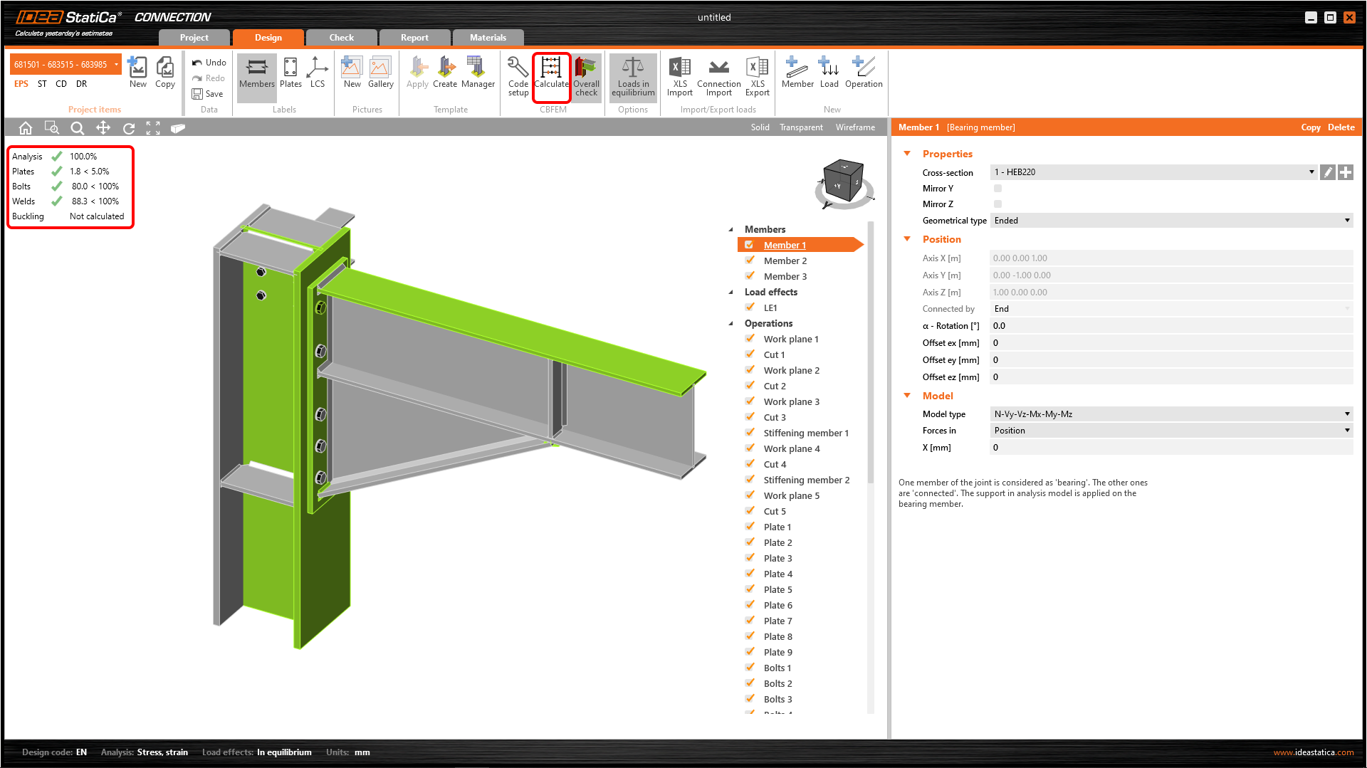
You can start the analysis by clicking Calculate in the ribbon. The analysis model is automatically generated, the calculation is performed and you can see the Overall check displayed together with basic values of check results.
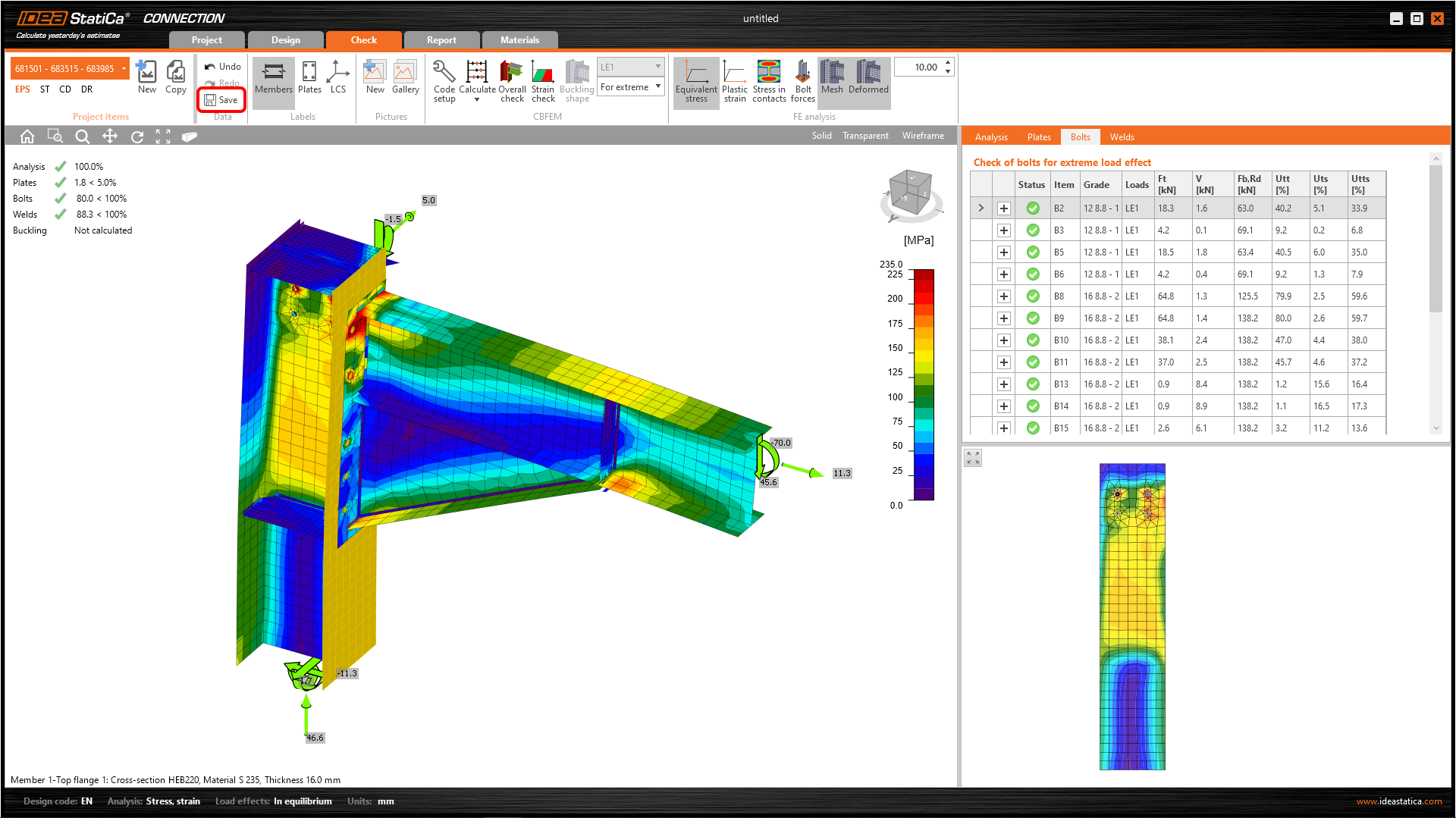
Go to the display tab Check and there activate Equivalent stress, Mesh, and Deformed from the ribbon to get a full picture of what is happening in the joint. To explore the detailed results for Bolts, expand the results for the bolt B3.

6 Report
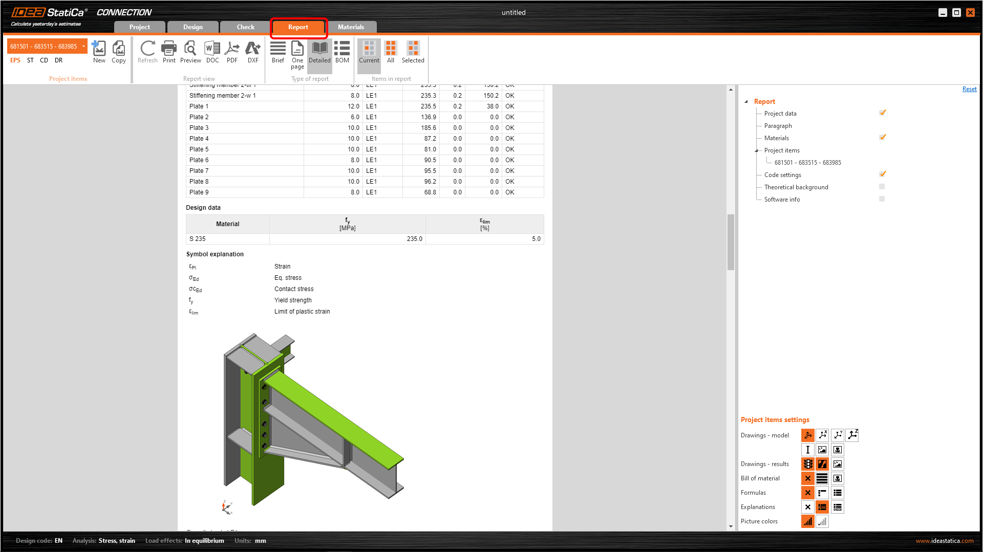
Next, go to the tab Report. IDEA StatiCa offers a fully customizable report to print out or save in an editable format.
You can take advantage of the Synchronize function. With this function, you can easily update an existing design of the IDEA StatiCa Connection project exported from the Tekla Structures. The originally defined Load effects are saved. This function is crucial to the link between the IDEA StatiCa project file and the Tekla Structures source file. You must not change the directory of the IDEA StatiCa project file or its name. You have to use the Save function.
And finally, close the Connection application window. Check out what kind of information is provided in the Code-check manager window.

7 Synchronize models
The design process is an iterative way how to mechanically arrange the structure parts in a way that it will work and pass the code-check. Usually, it takes a few changes in the whole process. Take advantage of the Synchronization function for the current item. For the sake of the example, you will change a few items.
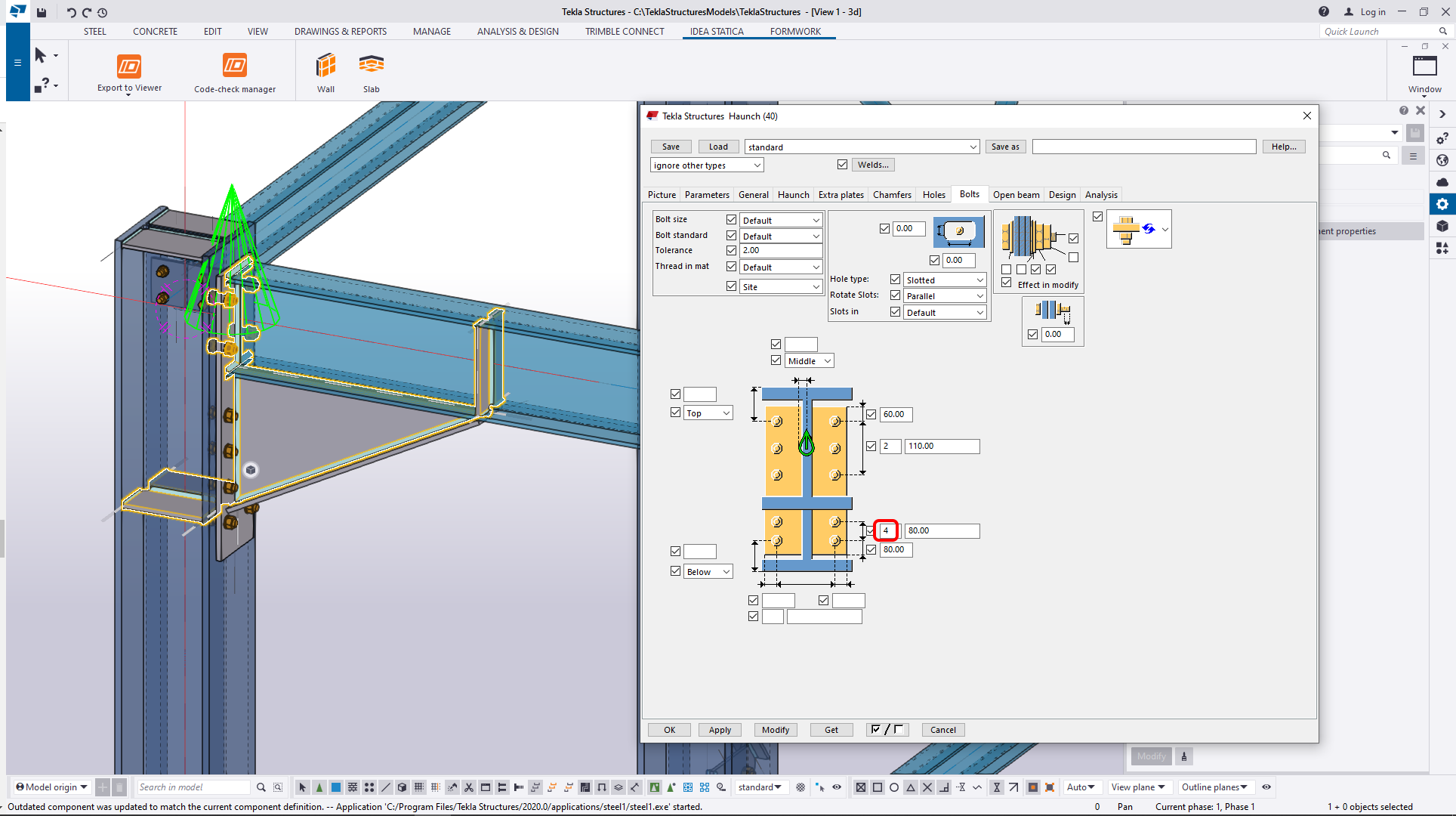
Just follow the figures below. First, lengthen the endplate.
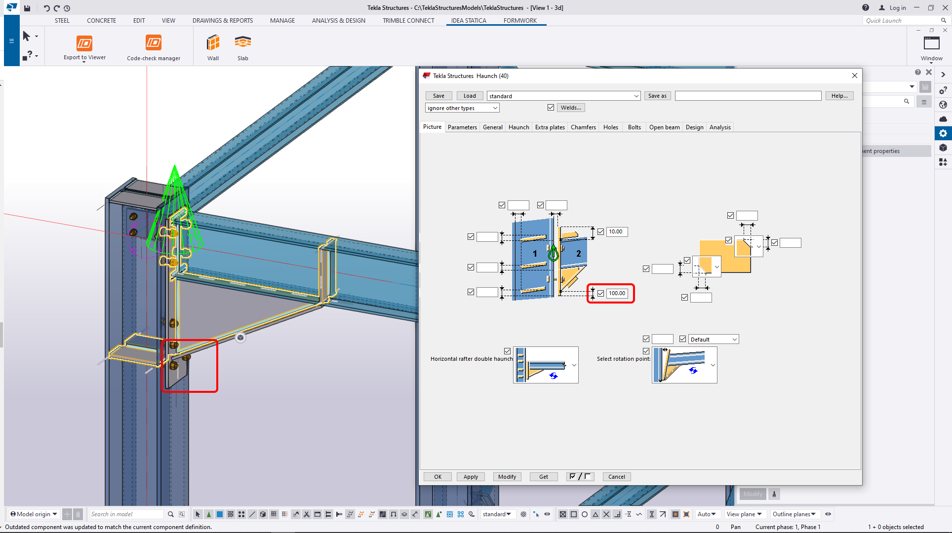
And add one row of bolts.
The change in the structural model is imminent and now you can choose to Synchronize (IDEA StatiCa detects changes in already imported entities – changes in thickness, changes in cross-section, modification of properties of welds, bolts, etc.) and update the project in IDEA StatiCa Connection. After a while, the connection data will be updated.

And in the next step, you can open the updated project.

Note:
Kindly be aware that IDEA StatiCa syncs with a model of the 3rd party application, not the other way around. If we add operations in IDEA StatiCa and then use the options described above (Synchronize/Synchronize All; Calculate/Calculate all), the additionally added operations will be deleted.
8 Import of other connections
For the tutorial demonstration, additional connections will be imported. According to the figure below, import the four other connections.
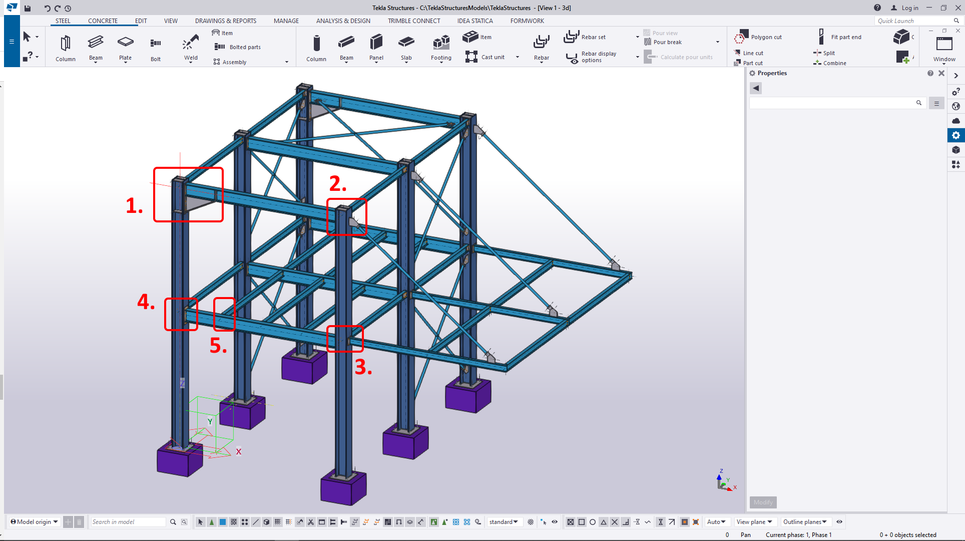
The second imported connection is the top part of one of the columns. Start with the Connection command in the Code-check manager and then the selection must be made. The figure below will guide you (A - node selection; B1,B2,B3,B4 - members; C - all other entities).

After the import, the Conn-2 will be listed in the Code-check manager, and connection components highlighted in the project window.

The third connection for import is a middle-right frame corner. After a successful import, you can see the list according to the picture below.

The fourth connection for import is the middle-left frame corner. After a successful import, you can see the list according to the picture below.

The fifth connection for import is the middle platform. After a successful import, you can see the list according to the picture below.

9 Update of more connections
Let's take advantage of the commands in the Code-check manager to update the model. You are going to do a different approach. If more changes in the project are needed and more exported joints are affected, you can use Synchronize all (tab All items) command. This will save your time and you will update the connection data in one push.
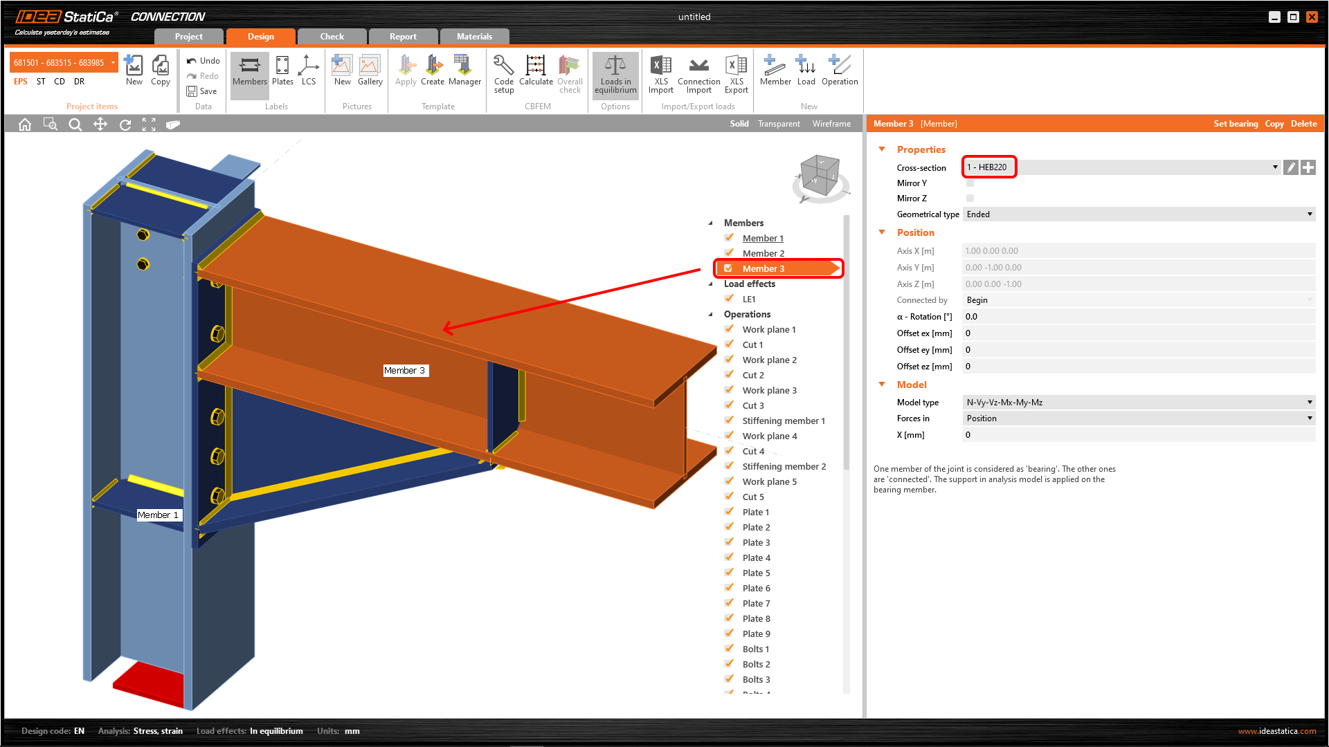
For example, you can change the cross-section, which is common for Conn-1 and Conn-2. The original one is IPE220. Change it to the HEB220 from the Tekla Structures library.

Now, proceed with the command Synchronize all (tab All items).

After a while, the synchronization process is done and we can open the Conn-1 or Conn-2 items and check out the cross-section of the member.
10 Known limitations
BIM link now works for a wide variety of connections/joints. However, please take into account the yet unsupported functionality:
Tips and limitations for exporting from Tekla Structures