Check of steel connection components (EN)
CBFEM method combines advantages of the general Finite Element Method (FEM) and standard Component Method (CM). The stresses and internal forces calculated on the accurate CBFEM model are used in checks of all components.
Individual components are checked according to Eurocode EN 1993-1-8.
Code-check of steel plates (EN)
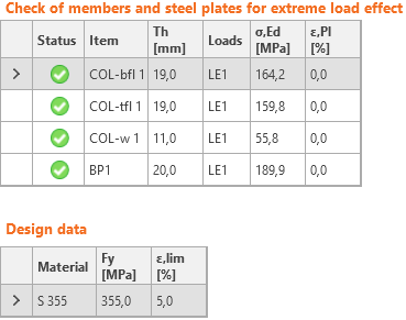
The resulting equivalent stress (Huber-Mises-Hencky – HMH, von Mises) and plastic strain are calculated on plates. The elasto-plastic material model is used for steel plates. A check of an equivalent plastic strain is performed. The limiting value of 5 % is suggested in Eurocode (EN 1993-1-5, app. C, par. C8, note 1), this value can be modified by the user in Code setup.
The plate element is divided across its thickness into five layers of finite element shells, and elastic/plastic behavior is investigated in each layer separately. Output summary lists the most critical check from all five layers.
CBFEM method can provide stress rather higher than yield strength. The reason is the slight inclination of the plastic branch of the stress-strain diagram, which is used in the analysis to improve the stability of interaction calculation. This is not a problem for practical design. At higher loads, the equivalent plastic strain rises, and the joint fails while exceeding the plastic strain limit.
Code-check of welds (EN)
Fillet welds are checked according to EN 1993-1-8. The strength of butt welds is assumed the same as the base metal and is not checked.
Fillet welds
Design resistance
The plastic redistribution in welds is used to automatically avoid the stress singularities in weld elements to redistribute the stress further along the weld length. The strength of the weld approximately matches the hand calculation, and the stress is correctly distributed for complicated issues like welding to an unstiffened flange (EN 1993-1-8 – Cl. 4.10). The stress in the throat section of a fillet weld is determined according to EN 1993-1-8 Cl. 4.5.3. Stresses are calculated from the stresses in weld element. Bending moment around the longitudinal weld axis is not taken into account.
\[ \sigma_{w,Ed}=\sqrt{\sigma_{\perp}^2 + 3 \left ( \tau_{\perp}^2 + \tau_{\parallel}^2 \right )} \]
\[ \sigma_{w,Rd} = \frac{f_u}{\beta_w \gamma_{M2}} \]
Weld utilization
\[ U_t = \min \left\{ \frac{\sigma_{{w,Ed}}}{\sigma_{w,Rd}}, \frac{\sigma_{\perp}}{0.9 f_u / {\gamma_{M2}}} \right\} \]
where:
- σw,Ed – equivalent stress in the weld
- σw,Rd – weld resistance
- βw – correlation factor (EN 1993-1-8 – Table 4.1)
- fu – ultimate strength, chosen as the lower of the two connected base materials or according to material chosen by user
- γM2 – safety factor (EN 1993-1-8 – Table 2.1; editable in Code setup)
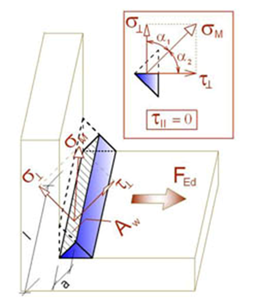
- σ┴, τ┴, τ‖ – stresses in weld according to the figure below:
All values required for check are printed in tables. Ut is the utilization of the most stressed element. Since plastic redistribution of stress in weld is used, it is the decisive utilization. Utc provides information about utilization along the weld length. It is the ratio of actual stress at all elements of the weld to the design resistance of the stress of the whole length of the weld.
The equivalent stress in the weld diagram shows the following stress:
\[ \sigma = \max \left \{ \frac{\sigma_{\perp}}{0.9 \beta_w}, \, \sqrt{\sigma_{\perp}^2 + 3 \tau_{\perp}^2 + 3 \tau_{\parallel}^2} \right \} \]
Butt welds
Welds can be specified as butt welds. Complete joint penetration is considered for butt welds, and therefore such welds are not checked.
Detailing
Minimum plate thickness of welded connections are checked according to EN 1993-1-8 – 4.1(1):
- For hollow steel section, the plate thickness should be at least 2.5 mm
- For other plates, the plate thickness should be at least 4 mm
Maximum weld throat thickness of fillet welds is checked for parallel plates. An error is issued, such weld is not feasible due to geometric constraints.
Minimum weld throat thickness of fillet welds should be at least 3 mm according to EN 1993-1-8 – 4.5.2(2). An error is issued when this requirement is not satisfied.
A warning is issued when weld throat thickness is smaller than the requirement in DIN EN 1993-1-8 – NA to 4.5.2:
\[a \le \sqrt{t_{max}}-0.5\]
where:
- \(a\) – weld throat thickness
- \(t_{max}\) – thickness of the thicker connected plate
- units must be in [mm]
Infomation is issued when weld throat thickness is smaller than the requirement for minimum ductility of welded joints in FprEN 1993-1-8:2023 – 6.9(4). This requirement is checked for double-sided fillet welds by:
\[a/t=\frac{\beta_w\gamma_{M2} f_y}{\sqrt{2} f_u \gamma_{M0} } \cdot \min \left \{1.0, 1.1\frac{f_y}{f_u} \right \}\]
where:
- \(a\) – weld throat thickness
- \(t\) – thickness of the plate connected by edge
- \(\beta_w\) – weld correlation factor
- \(\gamma_{M2}\) – safety factor for bolts and welds; editable in Code setup
- \(f_y\) – plate yield strength
- \(f_u\) – weld ultimate strength
- \(\gamma_{M0}\) – safety factor for plates; editable in Code setup
The weld throat thickness for single-sided fillet weld is twice larger than that for double-sided fillet weld.
Code-check of bolts and preloaded bolts (EN)
Bolts
The initial stiffness and design resistance of bolts in shear are in CBFEM modeled according to Cl. 3.6 and 6.3.2 in EN 1993-1-8. The spring representing bearing and tension has a bi-linear force-deformation behavior with an initial stiffness and design resistance according to Cl. 3.6 and 6.3.2 in EN 1993-1-8.
Design tension resistance of bolt (EN 1993-1-8 – Table 3.4):
\[ F_{t,Rd}=0.9 f_{ub} A_s / \gamma_{M2} \]
Design punching shear resistance of bolt head or nut (EN 1993-1-8 – Table 3.4):
\[ B_{p,Rd} = 0.6 \pi d_m t_p f_u / \gamma_{M2} \]
Design shear resistance per one shear plane (EN 1993-1-8 – Table 3.4):
\[ F_{v,Rd} = \alpha_v f_{ub} A_s / \gamma_{M2} \]
Design shear resistance can be multiplied by reduction factor βp if packing is present (EN 1993-1-8 – Cl. 3.6.1. (12)), and this option is selected in Code setup.
Design bearing resistance of plate (EN 1993-1-8 – Table 3.4):
\( F_{b,Rd} = k_1 \alpha_b f_u d t / \gamma_{M2} \) for standard holes
\( F_{b,Rd} = 0.6 k_1 \alpha_b f_u d t / \gamma_{M2} \) for slotted holes
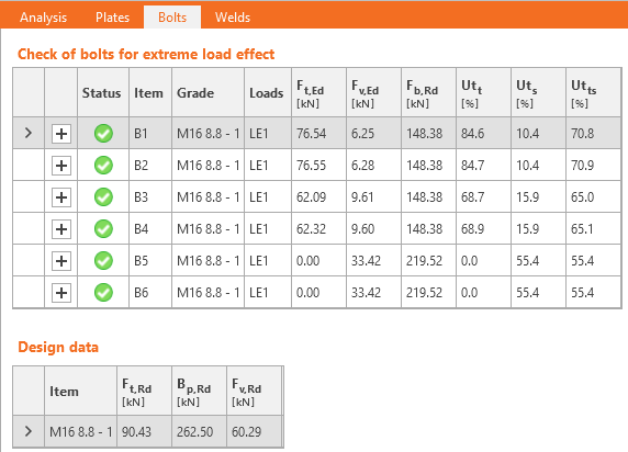
Utilization in tension [%]:
\[ Ut_t = \frac{F_{t,Ed}}{\min (F_{t,Rd},\, B_{p,Rd})} \]
Utilization in shear [%]:
\[ Ut_s = \frac{F_{v,Ed}}{\min (F_{v,Rd},\, F_{b,Rd})} \]
Interaction in shear and tension [%]:
\[ Ut_{ts}=\frac{F_{v,Ed}}{F_{v,Rd}}+\frac{F_{t,Ed}}{1.4 F_{t,Rd}} \]
where:
- As – tensile stress area of the bolt
- fub – ultimate tensile strength of the bolt
- dm – mean of the across points and across flats dimensions of the bolt head or the nut, whichever is smaller
- d – bolt diameter
- tp – plate thickness under the bolt head/nut
- fu – ultimate steel strength
- αv = 0.6 for grades 4.6, 5.6, 8.8 and 0.5 for grades 4.8, 5.8, 6.8, 10.9
- \( k_1 = \min \left \{2.8 \frac{e_2}{d_0}-1.7, \, 1.4 \frac{p_2}{d_0}-1.7, \, 2.5 \right \} \) – factor from Table 3.4
- \(\alpha_b = 1.0\) if the bearing check with \(\alpha_b\) is deactivated in Code setup; if the check is activated, the value of αb is determined according to EN 1993-1-8 – Table 3.4: \( \alpha_b = \min \left \{ \alpha_d, \, \frac{f_{ub}}{f_u}, \, 1.0 \right \} \)
- \(\alpha_d = \min \left \{ \frac{e_1}{3 d_0}, \, \frac{p_1}{3 d_0}-\frac{1}{4} \right \} \)
- e1, e2 – edge distances in the direction of the load and perpendicular to the load
- p1, p2 – bolt pitches in the direction of the load and perpendicular to the load
- Ft,Ed – design tensile force in bolt
- Fv,Ed – design shear force in bolt
- γM2 – safety factor (EN 1993-1-8 – Table 2.1; editable in Code setup)
Edge distances used for bolt bearing resistance must be relevant for general plate geometries, plates with openings, cutouts, etc.
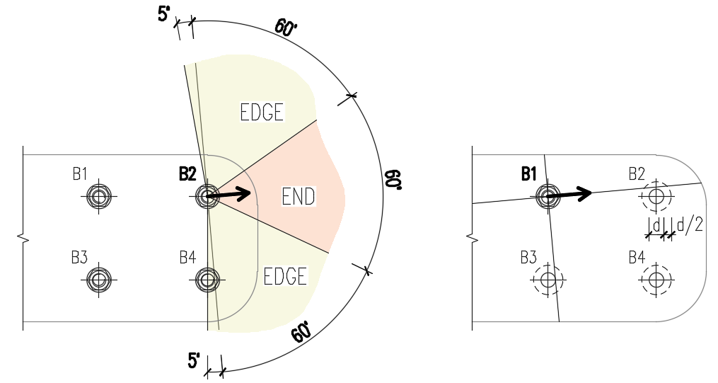
The algorithm reads the real direction of the resulting shear force vector in a given bolt and then calculates the distances needed for the bearing check.
The end (e1) and edge (e2) distances are determined by dividing the plate contour into three segments. The end segment is indicated by a 60° range in the direction of the force vector. The edge segments are defined by two 65° ranges perpendicular to the force vector. The shortest distance from a bolt to a relevant segment is then taken as an end, or an edge distance.
The spacing distances between bolt holes (p1; p2) are determined by virtually enlarging the surrounding bolt holes by half of their diameter, then drawing two lines in direction and perpendicular to the shear force vector. The distances to the enlarged bolt holes that are intersected by these lines are then considered as p1 and p2 in the calculation.
Bolts connecting thin-walled plates
Bolts connecting plates thinner than 3 mm, the provisions of EN 1993-1-3, Table 8.4 are used instead.
Bearing resistance:
\[F_{b,Rd}=2.5\cdot \alpha_b \cdot k_t \cdot f_u \cdot d \cdot t /\gamma_{M2}\]
where:
- \( \alpha_b=\min \left \{ 1.0, e_1/(3d) \right \} \)
- \(k_t = (0.8 t+1.5)/2.5 \) for 0.75 mm \(\le t \le\) 1.25 mm; \( k_t=1.0 \) for \(t>1.25\) mm
- \(f_u\) – ultimate strength of the connected plate
- \(d\) – bolt diameter
- \(t\) – thickness of the connected plate
- \(\gamma_{M2}\) – partial safety factor for connections editable in Code setup; by default \(\gamma_{M2}=1.25\)
Shear resistance, tension resistance, interaction of tension and shear, and punching shear resistance are determined according to EN 1993-1-8 – the same way as bolts connecting plates with a thickness higher than 3 mm.
Range of validity:
\[e_1 \ge 1.0 d_0 \]
\[p_1 \ge 3 d_0 \]
\[e_2 \ge 1.5 d_0 \]
\[p_2 \ge 3 d_0 \]
\[ f_u \le 550 \textrm{ MPa} \]
\[3 \textrm{ mm} > t \ge 0.75 \textrm{ mm} \]
Minimum bolt size: M6 – checked as \(d \ge 6\) mm
Bolt strength grades: 4.6 – 10.9 – checked as \(f_u \le 1000\) MPa
The bolts will be marked as failing if they are outside the range of validity.
Preloaded bolts
Design slip resistance per bolt grade 8.8 or 10.9 (EN 1993-1-8, Cl. 3.9 – Equation 3.8):
\[ F_{s,Rd} =\frac{k_s n \mu (F_{p,C} - 0.8 F_{t,Ed})}{\gamma_{M3}} \]
The preload (EN 1993-1-8 – Equation 3.7)
Fp,C = 0.7 fub As
The preloading force factor 0.7 can be modified in Code setup.
Utilization [%]:
\[ Ut_s = \frac{V}{F_{s,Rd}} \]
where:
- As – tensile stress area of the bolt
- fub – ultimate tensile strength
- ks – a coefficient (EN 1993-1-8 – Table 3.6; ks = 1 for normal round holes, ks = 0.63 for slotted holes)
- μ – slip factor editable in Code setup (EN 1993-1-8 – Table 3.7)
- n – number of the friction surfaces. Check is calculated for each friction surface separately
- γM3 – safety factor (EN 1993-1-8 – Table 2.1; editable in Code setup – recommended values are 1.25 for ultimate limit state and 1.1 for serviceability limit state design)
- V – design shear force in bolt
- Ft,Ed – design tensile force in bolt
If slip of preloaded bolts is checked for serviceability limit state, they should be afterward switched to "bearing – tension/shear interaction" and checked for the ultimate limit state.
Fire design
Preloaded bolts are assumed to slip, so that the checks of bearing bolts and preloaded bolts are the same.
Checks at fire and at ambient temperature are both performed and the minimum is selected as a design load resistance.
At elevated temperature, bolts are checked according to EN 1993-1-2, Annex D. Note that the area reduced by threads is always used in shear check according to D1.1.1.
Detailing
Detailing checks of bolts are performed if the option is selected in Code setup. Dimensions from bolt center to plate edges and between bolts are checked. Edge distance e = 1.2 and spacing between bolts p = 2.2 are recommended in Table 3.3 in EN 1993-1-8. User can modify both values in Code setup.
Minimum plate thickness of plates connected by bolts is checked. Plate thickness must be higher than 0.75 mm according to EN 1993-1-3 – Table 8.4.
Information is issued if ductility and rotation capacity requirements for bolted connection in tension according to EN 1993-1-8 – 6.4.2 are not met. If bolt is loaded predominantly in tension, the thinner connected plate should satisfy:
\[t \le 0,36d \sqrt{\frac{f_{ub}}{f_y}}\]
The default sizes of bolt assemblies are according to EN ISO 4014 – Hexagon bolt heads, EN ISO 4032 – Hexagon regular nuts, and EN ISO 7089 – Plain washers – Normal series – Product grade A.
Code-check of anchors (EN)
Four anchor bolt types are available:
- Straight (assumed post-installed)
- Washer plate - Circular (assumed cast-in)
- Washer plate - Rectangle (assumed cast-in)
- Hook (assumed cast-in)
The steel resistances are determined according to EN 1993-1-8 and EN 1992-4 for cast-in anchors and post-installed fasteners, respectively.
The concrete resistances are determined according to EN 1992-4.
In case of post-installed (straight) fasteners, pull-out failure, combined pull-out and concrete failure of bonded anchors, and concrete splitting failure are not checked due to missing information available only for the particular anchor and glue type from the anchor manufacturer.
In the Project settings, settings are available to activate/deactivate concrete cone breakout checks in tension and shear. If the concrete cone breakout check is not activated, it is assumed that the dedicated reinforcement is designed to resist the force. The magnitude of the force is provided in formulas. User may use link to Detail application to perform the checks of reinforced concrete.
Furthermore, the concrete can be set as cracked or uncracked. Uncracked concrete should be in permanent compression that prevents shrinkage cracks. The resistances of uncracked concrete are higher.
Tensile steel resistance (EN 1993-1-8, Table 3.4)
Cast-in anchors are checked according to steel design code.
\[ F_{t,Rd} = \frac{c \cdot k_2 \cdot f_{ub} \cdot A_s}{\gamma_{M2}} \]
where:
- c – decrease in tensile resistance of bolts with cut thread according to EN 1993-1-8 – Cl. 3.6.1. (3) editable in Project Settings
- k2 = 0.9 – factor for non-countersunk anchors
- fub – anchor bolt ultimate tensile strength
- As – anchor bolt tensile stress area
- \(\gamma_{M2}=1.25\) – partial safety factor for bolts (EN 1993-1-8, Table 2.1) editable in Project Settings
Tensile steel resistance (EN 1992-4, Cl. 7.2.1.3)
Post-installed fasteners are checked according to concrete design code
\[ N_{Rd,s} = \frac{N_{Rk,s}}{\gamma_{Ms}} \]
where:
- NRk,s = c ∙ As ∙ fuk – characteristic resistance of a fastener in case of steel failure
- c – decrease in tensile resistance of bolts with cut thread according to EN 1993-1-8 – Cl. 3.6.1. (3) editable in Code setup
- As – anchor bolt tensile stress area
- fuk – anchor bolt characteristic ultimate tensile strength
- \(\gamma_{Ms}=1.2 \cdot \frac{f_{uk}}{f_{yk}} \ge 1.4\) – partial safety factor for steel failure in tension (EN 1992-4, Table 4.1)
- fyk – anchor bolt characteristic yield strength
Concrete cone failure resistance of anchor or group of anchors (EN 1992-4, Cl. 7.2.1.4):
\[ N_{Rd,c} = \frac{N_{Rk,c}}{\gamma_{Mc}} \]
where:
- \(N_{Rk,c}=N_{Rk,c}^0 \cdot \frac{A_{c,N}}{A_{c,N}^0} \cdot \psi_{s,N} \cdot \psi_{re,N} \cdot \psi_{ec,N} \cdot \psi_{M,N}\) – characteristic resistance of a fastener, a group of fasteners and the tensioned fasteners of a group of fasteners in case of concrete cone failure
- \(N_{Rk,c}^0 = k_1 \sqrt{f_{ck}} h_{ef}^{1.5}\) – characteristic resistance of a single fastener placed in concrete and not influenced by adjacent fasteners or edges of the concrete member
- k1 – factor taking into account concrete condition and anchor type; for cast-in headed anchors (with washer plates) k1 = 8.9 for cracked concrete and k1 = 12.7 for non-cracked concrete; for post-installed fasteners (straight anchors) k1 = 7.7 for cracked concrete and k1 = 11.0 for non-cracked concrete
- fck – characteristic concrete compressive cylinder strength
- hef – embedment depth of the anchor in concrete; for three or more close edges, EN 1992-4, Cl. 7.2.1.4 (8) applies and effective \(h'_{ef} = \max \left \{ \frac{c_{max}}{c_{cr,N}} \cdot h_{ef}, \, \frac{s_{max}}{s_{cr,N}} \cdot h_{ef} \right \}\) is used instead in formulas for NRk,c0, ccr,N, scr,N, Ac,N, Ac,N0, ψs,N, and ψec,N
- Ac,N – actual projected area, limited by overlapping concrete cones of adjacent fasteners as well as by edges of the concrete member
- Ac,N0 = scr,N2 – reference projected area, i.e. area of concrete of an individual anchor with large spacing and edge distance at the concrete surface
- \(\psi_{s,N}=0.7+0.3 \cdot \frac{c}{c_{cr,N}} \le 1\) – factor taking into account disturbance of the distribution of stresses in the concrete due to the proximity of an edge of the concrete member
- c – smallest edge distance
- ccr,N = 1.5 ∙ hef – characteristic edge distance for ensuring the transmission of the characteristic resistance of an anchor in case of concrete break-out under tension loading
- \(\psi_{re,N}=0.5+\frac{h_{ef}}{200} \le 1\) – shell spalling factor
- \(\psi_{ec,N}=\frac{1}{1+2 \cdot (e_N / s_{cr,N})} \le 1\) – factor taking into account group effect when different tension loads are acting on the individual fasteners of a group; ψec,N is determined separately for each direction and the product of both factors is used
- eN – eccentricity of resultant tension force of tensioned fasteners in respect to the center of gravity of the tensioned fasteners
- scr,N = 2 ∙ ccr,N – characteristic spacing of anchors to ensure the characteristic resistance of the anchors in case of concrete cone failure under tension load
- \(\psi_{M,N} = 2- \frac{z}{1.5 \cdot h_{ef}} \ge 1\) – factor taking into account effect of a compression force between fixture and concrete in cases of bending moments with or without axial force; this parameter is equal to 1 if c < 1.5 hef or the ratio of the compressive force (including the compression due to bending) to the sum of tensile forces in anchors is smaller than 0.8 or z / hef ≥ 1.5
- z – internal lever arm of a fastening
- γMc = γc ∙ γinst – partial safety factor (EN 1992-4, Table 4.1)
- γc – partial safety factor for concrete (editable in Code setup)
- γinst – partial safety factor taking account of the installation safety of an anchor system (editable in Code setup)
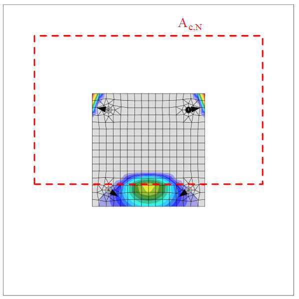
The concrete breakout cone area for a group of anchors loaded by tension that creates a common concrete cone, Ac,N, is shown by the red dashed line.
Pull-out resistance (EN 1992-4, Cl. 7.2.1.5)
Pull-out resistance is checked for cast-in anchors with washer plates according to EN 1992-4, Cl. 7.2.1.5:
\[ N_{Rd,p}=\frac{N_{Rk,p}}{\gamma_{Mc}} \]
where:
- NRk,p = k2 ∙ Ah ∙ fck – characteristic resistance in case of pull-out failure
- k2 – coefficient dependent on concrete condition, k2 = 7.5 for cracked concrete, k2 = 10.5 for non-cracked concrete
- Ah – bearing area of head of anchor; for circular washer plate \(A_h = \frac{\pi}{4} \left ( d_h^2 - d^2 \right )\), for rectangular washer plate \(A_h = a_{wp}^2 - \frac{\pi}{4} d^2\)
- dh ≤ 6 th + d – diameter of the head of the fastener
- th – thickness of the head of the headed fastener
- d – diameter of the shank of the fastener
- fck – characteristic concrete compressive cylinder strength
- γMc = γc ∙ γinst – partial safety factor (EN 1992-4, Table 4.1)
- γc – partial safety factor for concrete (editable in Code setup)
- γinst – partial safety factor taking account of the installation safety of an anchor system (editable in Code setup)
Pull-out resistance (EN 1992-1-1, Cl. 8.4.4)
Pull-out resistance is checked for cast-in anchors with hook according to EN 1992-1-1, Cl. 8.4.4. Plain rods are assumed that require double anchorage length than ribbed reinforcement (Table 3.26 in BS 8110-1).
\[N_{Rd,p}=A_a \cdot f_{ya} \cdot \frac{l_b}{l_{bd}}\]
where:
- Aa – tensile stress area of an anchor
- fya – anchor yield strength
- lb – anchor length embedded in concrete
- \(l_{bd} = \alpha_1 \cdot \alpha_2 \cdot \alpha_3 \cdot \alpha_4 \cdot \alpha_5 \cdot l_{b,rqd}\) – design anchorage length
- \(\alpha_1\) – factor for the effect of the shape of the bars assuming adequate cover
- \(\alpha_1 = 0.7\) for \(c_d > 3 \phi\)
- \(\alpha_1 = 1.0\) for \(c_d \le 3 \phi\)
- \(c_d = \min \{a/2, c_1\}\) – adequate cover
- a – clear distance between anchors
- c1 – clear distance to concrete block edge
- \(\phi\) – anchor diameter
- \(\alpha_2 = 1.0 - 0.15 \frac{c_d - \phi}{\phi}\) – factor for the effect of concrete minimum cover; \(0.7 \le \alpha_2 \le 1.0\)
- \(\alpha_3 = 1.0\) – factor for the effect of confinement by transverse reinforcement
- \(\alpha_4 = 1.0 \) – factor for the influence of one or more welded transverse bars along the design anchorage length
- \(\alpha_5=1.0\) – factor for the effect of the pressure transverse to the plane of splitting along the design anchorage length
- \(l_{b,rqd} = \frac{\phi}{4} \frac{f_{ya}}{f_{bd}}\) – required anchorage length
- \(f_{bd} = \frac{2.25 \cdot \eta_1 \cdot \eta_2 f_{ctd}}{2}\) – design value of the ultimate bond stress (assumed half that of ribbed reinforcement)
- \(\eta_1=1.0\) – coefficient related to the quality of the bond condition and the position of the bar during concreting; good conditions are assumed, which may be dangerous for the rare case of horizontal anchors placed at the top of the concrete
- \(\eta_2=\min \{1.0, \frac{132-\phi}{100}\) – coefficient related to the bar diameter
- \(f_{ctd}=\frac{\alpha_{ct} \cdot f_{ctk,0.05}}{\gamma_c}\) – design value of concrete tensile strength
- \(\alpha_{ct}=1.0\) – coefficient taking account of long term effects on the tensile strength and of unfavourable effects
- \(f_{ctk,0.05}\) – characteristic axial tensile strength of concrete (5% quantile)
- \(\gamma_c\) – safety factor for concrete editable in Project Settings
Several detailing rules are added:
- Anchor yield strength must not be higher than 300 MPa (EN 1993-1-8 – 6.2.6.12 (5))
- Minimum anchorage length \(l_{b,min}\) must be kept (EN 1992-1-1 – Equation (8.6)):
\[ l_b \ge l_{b,min} = \max \{ 0.3 \cdot l_{b,rqd}, 10\cdot \phi , 100 \}\]
- Anchorage length should be sufficient for the steel tensile failure mode to govern to facilitate plastic design
The pullout resistance of other types of anchors is not checked and must be guaranteed by the manufacturer.
Concrete blowout resistance (EN 1992-4, Cl. 7.2.1.8)
Blow-out failure is checked for cast-in headed anchors (Anchor type – washer) with edge distance c ≤ 0.5 hef according to EN 1992-4, Cl. 7.2.1.8. Anchors are treated as a group if their spacing near the edge is s ≤ 4 c1. Undercut anchors can be checked the same way but the value of Ah is unknown in the software. The blow-out failure of undercut anchors can be determined by selecting a washer plate with the corresponding dimension.
\[N_{Rd,cb} = \frac{N_{Rk,cb}}{\gamma_{Mc}}\]
where:
- \(N_{Rk,cb} = N_{Rk,cb}^0 \cdot \frac{A_{c,Nb}}{A_{c,Nb}^0} \cdot \psi_{s,Nb} \cdot \psi_{g,Nb} \cdot \psi_{ec,Nb}\) – characteristic resistance in case of concrete blow-out failure
- \(N_{Rk,cb}^0 = k_5 \cdot c_1 \cdot \sqrt{A_h} \cdot \sqrt{f_{ck}}\) – characteristic resistance of a single fastener, not influenced by adjacent fasteners or further edges
- Ac,Nb – actual projected area, limited by overlapping concrete break-out bodies of adjacent fasteners as well as by proximity of edges of the concrete member or the member thickness
- Ac,Nb0 = (4 c1)2 – reference projected area of a single fastener with an edge distance equal to c1
- \(\psi_{s,Nb} = 0.7+0.3 \frac{c_2}{2 c_1} \le 1\) – factor taking into account the disturbance of the distribution of stresses in the concrete due to the proximity of a corner of the concrete member
- \( \psi_{g,Nb} = \sqrt{n} + (1-\sqrt{n}) \frac{s_2}{4c_1} \ge 1 \) – factor taking into account group effect
- \(\psi_{ec,Nb} = \frac{1}{1+2 e_N / s_{cr,Nb}} \le 1\) – factor taking into account group effect, when different loads are acting on the individual fasteners of a group
- k5 – parameter related to the state of the concrete; for cracked concrete k5 = 8.7, for uncracked concrete k5 = 12.2
- c1 – edge distance of fastener in direction 1 towards the closest edge
- c2 – edge distance of fastener perpendicular to direction 1 that is the smallest edge distance in a narrow member with multiple edge distances
- Ah – area of the load-bearing head of the fastener; for circular washer plate \(A_h = \frac{\pi}{4} \left ( d_h^2 - d^2 \right )\), for rectangular washer plate \(A_h = a_{wp}^2 - \frac{\pi}{4} d^2\)
- d – anchor nominal diameter
- dh – circular washer plate diameter
- awp – side size of squared washer plate
- fck – characteristic compressive cylinder strength of concrete
- n – number of fasteners in a row parallel to the edge of the concrete member
- s2 – spacing of fasteners in a group perpendicular to direction 1
- scr,Nb = 4 c1 – spacing that is required for a fastener to develop its characteristic tensile strength against blow-out failure
Anchor shear steel resistance (EN 1993-1-8 – Cl. 6.2.2)
Anchor shear steel resistance of cast-in anchors is determined according to EN 1993-1-8 – 6.2.2 (7) regardless of direct or mortar joint stand-off. The addition of friction is problematic in practice and is not assumed. The background for Eurocode calculation is the Stevin Laboratory model presented in this paper. Holes should be standard, not oversized and the grout strength and thickness should be according to Cl. 6.2.5 (7).
\[F_{vb,Rd} = \min \{F_{1vb,Rd}, F_{2vb,Rd} \} \]
where:
- \(F_{1vb,Rd} = \frac{\alpha_v \cdot f_{ub} \cdot A}{\gamma_{M2}}\) – anchor shear resistance from Table 3.4
- αv = 0.6 for grades 4.6, 5.6, 8.8 and 0.5 for grades 4.8, 5.8, 6.8, 10.9
- fub – ultimate tensile strength of the bolt
- A – tensile stress area of the bolt
- A = A for shear plane excluded from threads; A is gross cross-section area of the anchor
- A = As for shear plane intercepted by threads; As is tensile stress area of the bolt
- γM2 – safety factor (EN 1993-1-8 – Table 2.1; editable in Project Settings)
- \(F_{2vb,Rd} = \frac{\alpha_b \cdot f_{ub} \cdot A_s}{\gamma_{M2}}\) – anchor shear resistance from Equation (6.2)
- \(\alpha_b = 0.44 - 0.0003 f_{yb}\) – coefficient depending on the yield strength the anchor bolt
- fyb – anchor yield strength; 235 MPa \(\le f_{yb} \le\) 640 MPa
- fub – anchor tensile strength
- As – tensile stress area
Anchor shear steel resistance (EN 1992-4 – Cl. 7.2.2.3)
Anchor shear steel resistance of post-installed fasteners is checked according to EN 1992-4 – Cl. 7.2.2.3. Friction is not taken into account. Shear with and without lever arm is recognized in dependence on base plate manufacturing operation settings.
\[V_{Rd,s} = \frac{V_{Rk,s}}{\gamma_{Ms}}\]
For stand-off: direct, the shear without lever arm is assumed (EN 1992-4 – Cl. 7.2.2.3.1):
VRk,s = k6 ∙ As ∙ fuk – characteristic resistance of a single fastener in case of steel failure; or fasteners with a ratio hef / dnom < 5 and a concrete compressive strength class < C20/25 the characteristic resistance VRk,s should be multiplied by a factor of 0.8.
For stand-off: mortar joint, the shear with lever arm is assumed (EN 1992-4 – Cl. 7.2.2.3.2):
\[V_{Rk,s}= \frac{\alpha_M \cdot M_{Rk,s}}{l_a}\]
where:
- k6 = 0.6 for anchors with fuk ≤ 500 MPa; k6 = 0.5 otherwise
- As – shear area of anchor; if shear plane in a thread is selected, the area reduced by threads is used; otherwise, full shank area is used
- fuk – anchor bolt ultimate strength
- αM = 2 – full restraint is assumed (EN 1992-4 – Cl. 6.2.2.3)
- \( M_{Rk,s} = M_{Rk,s}^0 \left ( 1 - \frac{N_{Ed}}{N_{Rd,s}} \right ) \) – characteristic bending resistance of the anchor decreased by the tensile force in the anchor
- MRk,s0 = 1.2 Wel fub – characteristic bending resistance of the anchor (ETAG 001, Annex C – Equation (5.5b))
- \( W_{el} = \frac{\pi d^3}{32}\) – section modulus of the anchor
- d – anchor bolt diameter; if the shear plane in a thread is selected, the diameter reduced by threads is used; otherwise, nominal diameter, dnom, is used
- NEd – tensile force in the anchor
- NRd,s – tensile resistance of the anchor
- la = 0.5 dnom + tmortar + 0.5 tbp – lever arm
- tmortar – thickness of mortar (grout)
- tbp – thickness of the base plate
- γMs = 1.0 ∙ fuk / fyk ≥ 1.25 for fuk ≤ 800 MPa and fyk / fuk ≤ 0.8; γMs = 1.5 otherwise – partial safety factor for steel failure (EN 1992-4 – Table 4.1)
Concrete pry-out failure (EN 1992-4 – Cl. 7.2.2.4):
\[ V_{Rd,cp}= \frac{V_{Rk,cp}}{\gamma_{Mc}} \]
where:
- VRk,cp = k8 ∙ NRk,c – characteristic resistance of concrete pry-out failure
- k8 = 1 for hef < 60 mm; k8 = 2 for hef ≥ 60 mm (ETAG 001, Annex C – Cl. 5.2.3.3)
- NRk,c – characteristic resistance of a fastener, a group of fasteners, and the tensioned fasteners of a group of fasteners in case of concrete cone failure; all anchors are assumed to be in tension
- γMc = γc – partial safety factor (EN 1992-4 – Table 4.1, γinst = 1.0 for shear loading)
- γc – partial safety factor for concrete (editable in Code setup)
Concrete edge failure (EN 1992-4 – Cl. 7.2.2.5):
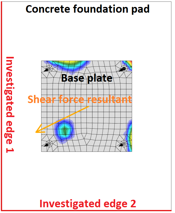
Concrete edge failure is a brittle failure, and the worst possible case is checked, i.e. only the anchors located near the edge transfer the full shear load acting on a whole base plate. If anchors are positioned in a rectangular pattern, the row of anchors at the investigated edge transfers the shear load. If anchors are positioned irregularly, the two anchors nearest to the investigated edge transfer the shear load. Two edges in the direction of the shear load are investigated, and the worst case is shown in the results.
Investigated edges in dependence on the direction of the shear force resultant
\[ V_{Rd,c} = \frac{V_{Rk,c}}{\gamma_{Mc}} \]
where:
- \( V_{Rk,c}= V_{Rk,c}^0 \cdot \frac{A_{c,V}}{A_{c,V}^0} \cdot \psi_{s,V} \cdot \psi_{h,V} \cdot \psi_{ec,V} \cdot \psi_{\alpha,V} \cdot \psi_{re,V} \) – characteristic resistance of a fastener or a group of fasteners loaded towards the edge
- \( V_{Rk,c}^0 = k_9 \cdot d_{nom}^\alpha \cdot l_f^\beta \cdot f_{ck}^{0.5} \cdot c_1^{1.5}\) – initial value of the characteristic resistance of a fastener loaded perpendicular to the edge
- k9 – factor taking into account concrete condition; k9 = 1.7 for cracked concrete, k9 = 2.4 for non-cracked concrete
- \( \alpha = 0.1 \left ( \frac{l_f}{c_1} \right ) ^{0.5} \)
- \( \beta = 0.1 \left ( \frac{d_{nom}}{c_1} \right ) ^{0.2} \)
- lf = min (hef, 12 dnom) for dnom ≤ 24 mm; lf = min [hef, max (8 dnom, 300 mm)] for dnom > 24 mm – effective length of the anchor in shear
- hef – embedment depth of the anchor in concrete
- c1 – distance from the anchor to the investigated edge; for fastenings in a narrow, thin member, the effective distance \( c'_1=\max \left \{ \frac{c_{2,max}}{1.5}, \, \frac{h}{1.5}, \, \frac{s_{2,max}}{3} \right \} \) is used instead
- c2 – smaller distance to the concrete edge perpendicular to the distance c1
- dnom – nominal anchor diameter
- Ac,V0 = 4.5 c12 – area of a concrete cone of an individual anchor at the lateral concrete surface not affected by edges
- Ac,V – actual area of the concrete cone of the anchorage at the lateral concrete surface
- \(\psi_{s,V} = 0.7+0.3 \frac{c_2}{1.5 c_1} \le 1.0 \) – factor which takes account of the disturbance of the distribution of stresses in the concrete due to further edges of the concrete member on the shear resistance
- \( \psi_{h,V} = \left ( \frac{1.5 c_1}{h} \right ) ^ {0.5} \ge 1.0 \) – factor which takes account of the fact that the shear resistance does not decrease proportionally to the member thickness as assumed by the ratio Ac,V / Ac,V0
- \( \psi_{ec,V} = \frac{1}{1+2 e_V / (3c_1)} \le 1 \) – factor which takes account of a group effect when different shear loads are acting on the individual anchors of a group
- \( \psi_{\alpha,V} = \sqrt{\frac{1}{(\cos \alpha_V)^2 + (0.5 \sin \alpha_V)^2}} \ge 1 \) – takes account of the angle αV between the load applied, V, and the direction perpendicular to the free edge of the concrete member
- ψre,V = 1.0 – factor takes account of the effect of the type of reinforcement used in cracked concrete
- h – concrete block height
- γMc = γc – partial safety factor (EN 1992-4 – Table 4.1, γinst = 1.0 for shear loading)
- γc – partial safety factor for concrete (editable in Code setup)
Interaction of tension and shear in steel (EN 1993-1-8 – Table 3.4)
The interaction of tension and shear for cast-in anchors is determined separately for steel and concrete. Steel failure mode is checked according to EN 1993-1-8 – Table 3.4. The interaction in steel is checked for each anchor separately.
\[ \frac{V_{Ed}}{F_{v,Rd}} + \frac{N_{Ed}}{1.4 \cdot F_{t,Rd}} \le 1.0 \]
Interaction of tension and shear in steel (EN 1992-4 – Table 7.3)
The interaction of tension and shear for post-installed fasteners is determined separately for steel and concrete failure modes according to Table 7.3. Interaction in steel is checked according to Equation (7.54). The interaction in steel is checked for each anchor separately.
\[ \left ( \frac{N_{Ed}}{N_{Rd,s}} \right )^2 + \left ( \frac{V_{Ed}}{V_{Rd,s}} \right )^2 \le 1.0 \]
Interaction of tension and shear in concrete
Interaction in concrete is checked according to Equation (7.55).
\[ \left ( \frac{N_{Ed}}{N_{Rd,i}} \right )^{1.5} + \left ( \frac{V_{Ed}}{V_{Rd,i}} \right )^{1.5} \le 1.0 \]
The largest value of \(N_{Ed} / N_{Rd,i} \) and \(V_{Ed} / V_{Rd,i} \) for the different failure modes shall be taken. Note that values of \(N_{Ed}\) and \(N_{Rd,i}\) often belong to a group of anchors.
Anchors with stand-off
An anchor with stand-off is designed as a bar element loaded by shear force, bending moment, and compressive or tensile force. These internal forces are determined by the finite element model. The anchor is fixed on both sides, one side is 0.5×d below the concrete level, and the other side is in the middle of the thickness of the plate. The buckling length is conservatively assumed as twice the length of the bar element. Plastic section modulus is used. The bar element is designed according to EN 1993-1-1. The shear force may decrease the yield strength of the steel according to Cl. 6.2.8 but the minimum length of the anchor to fit the nut under the base plate ensures that the anchor fails in bending before the shear force reaches half the shear resistance. The reduction is therefore not necessary. The interaction of bending moment and compressive or tensile strength is assessed according to Cl. 6.2.1.
Shear resistance (EN 1993-1-1 Cl. 6.2.6):
\[ V_{pl,Rd} = \frac{A_V f_y / \sqrt{3}}{\gamma_{M2}} \]
where:
- AV = 0.844 As – shear area
- As – bolt area reduced by threads
- fy – bolt yield strength
- γM2 – partial safety factor
Tensile resistance (EN 1993-1-8 – Cl. 3.6.1):
\[ F_{t,Rd}=\frac{c k_2 f_{ub} A_s}{\gamma_{M2}} \ge F_t \]
where:
- c – decrease in tensile resistance of bolts with cut thread according to EN 1993-1-8 – Cl. 3.6.1. (3) editable in Code setup
- k2 = 0.9 – factor from Table 3.4 in EN 1993-1-8
- fub – anchor bolt ultimate strength
- As – anchor bolt tensile stress area
- γM2 – safety factor (EN 1993-1-8 – Table 2.1; editable in Code setup)
Compressive resistance (EN 1993-1-1 Cl. 6.3):
\[ F_{c,Rd} = \frac{\chi A_s f_y}{\gamma_{M2}} \]
where:
- \( \chi = \frac{1}{\Phi + \sqrt{\Phi^2 - \bar\lambda^2}} \le 1 \) – buckling reduction factor
- \( \Phi = 0.5 \left [1+ \alpha (\bar\lambda - 0.2) + \bar\lambda^2 \right ] \) – value to determine buckling reduction factor χ
- α = 0.49 – imperfection factor for buckling curve c (belonging to the full circle)
- \( \bar\lambda = \sqrt{\frac{A_s f_y}{N_{cr}}} \) – relative slenderness
- \( N_{cr} = \frac{\pi^2 E I}{L_{cr}^2} \) – Euler's critical force
- \( I = \frac{\pi d_s^4}{64} \) – moment of inertia of the bolt
- Lcr = 2 l – buckling length; it is assumed on the safe side that the bolt is fixed in the concrete and able to rotate at the base plate freely
- l – length of the bolt element equal to half the base plate thickness + gap + half the bolt diameter; it is assumed on the safe side that the washer and a nut are not clamped to the concrete surface (ETAG 001 – Annex C – Cl. 4.2.2.4)
Bending resistance (EN 1993-1-1 Cl. 6.2.5):
\[ M_{pl,Rd} = \frac{W_{pl} f_y}{\gamma_{M2}} \]
- \( W_{pl}= \frac{d_s^3}{6} \) – section modulus of the bolt
- fy – bolt yield strength
- γM2 – partial safety factor
Anchor steel utilization (EN 1993-1-1 Cl. 6.2.1)
\[ \frac{N_{Ed}}{N_{Rd}} + \frac{M_{Ed}}{M_{Rd}} \le 1 \]
where:
- NEd – tensile (positive) or compressive (negative sign) design force
- NRd – tensile (positive, Ft,Rd) or compressive (negative sign, Fc,Rd) design resistance
- MEd – design bending moment
- MRd = Mpl,Rd – design bending resistance
Detailing
A detailing check of anchors is performed if the option is selected in the Code setup. Only minimum spacing between anchors (measured centreline to centreline) is checked. The minimum spacing differs for each anchor type and is given in the European Technical Product Specification. Users can modify limit spacing value in the Code setup as a multiple of anchor bolt diameter.
Edge distances to steel plates follow the rules for bolts, i.e. e = 1.2 is recommended in Table 3.3 in EN 1993-1-8. User can modify this value in Code setup.
Code-check of concrete blocks (EN)
Concrete below the base plate is simulated by the Winkler subsoil with uniform stiffness, which provides the contact stresses. The average stress at the effective area determined by EN 1993-1-8 is used for compressive check.
The resistance of concrete in 3D compression is determined based on EN 1993-1-8 by calculating the design bearing strength of concrete in the joint, fjd, under the effective area, Aeff, of the base plate. The design bearing strength of the joint, fjd, is evaluated according to Cl. 6.2.5 in EN 1993-1-8 and Cl. 6.7 in EN 1992-1-1. The grout quality and thickness is introduced by the joint coefficient, βjd. For grout quality equal or better than the quality of the concrete block, βjd = 1.0 is expected, EN 1993-1-8 recommends value βjd = 0.67. The effective area, Aeff,cm under the base plate is estimated to be of the shape of the column cross-section increased by additional bearing width, c.
\[ c = t \sqrt{\frac{f_y}{3 f_{jd} \gamma_{M0}}} \]
where t is the thickness of the base plate, fy is the base plate yield strength, and γM0 is the partial safety factor for steel.
The effective area is calculated by iteration until the difference between the additional bearing widths of current and previous iteration |ci – ci–1 | is less than 1 mm. For the first iteration, the area of the base plate is assumed as a bearing area, Ac0.
The area where the concrete is in compression is taken from results of FEA. This area in compression, Aeff,FEM, allows determining the position of the neutral axis. The user can modify this area by editing “Effective area – influence of mesh size” in Code setup. The default value is 0.1 for which the verification studies were made. It is not recommended to decrease this value. Increasing this value makes the assessment of concrete bearing resistance safer. The value in Code setup determines the boundary of the area, Aeff,FEM, e.g. the value of 0.1 takes into account only areas where stress in concrete is higher than 0.1 times the maximum stress in concrete, σc,max. The intersection of the area in compression, Aeff,FEM, and the effective area, Aeff,cm, allows to assess the resistance for generally loaded column base of any column shape with any stiffeners and is labeled Aeff. The average stress σ on the effective area, Aeff, is determined as the compression force divided by the effective area. Check of the component is in stresses σ ≤ fjd.
Concrete resistance at concentrated compression:
\[ f_{jd}= \beta_j k_j \frac{f_{ck}}{\gamma_c} \]
Concentration factor taking into account increase in concrete compressive resistance due to triaxial stress:
\[ k_j=\sqrt{\frac{A_{c1}}{A_{eff}}} \le 3.0 \]
where Ac1 is the supporting area determined according to EN 1992-1-1 – Cl. 6.7. The area must be concentric and geometrically similar to the bearing area Aeff.
Average stress under the base plate:
\[ \sigma = \frac{N}{A_{eff}} \]
Utilization in compression [%]:
\[ Ut = \frac{\sigma}{f_{jd}} \]
where:
- fck – characteristic compressive concrete strength
- βj = 0.67 – factor of grout quality editable in Code setup
- γc – safety factor for concrete
- Aeff – effective area on which the column normal force N is distributed
Effective area, Aeff,cm, as calculated according to EC for pure compression, is marked with a dashed line. The graphical representation shows the way of checking. Calculated effective area, Aeff,fem, is marked as green. The final effective area, Aeff, for contact stress check is highlighted as hatched.
For rare occasions, especially for column base loaded by tensile force only (compression in concrete is caused by prying forces) or tensile force and bending moment, the intersection of areas Aeff,cm and Aeff,fem is extremely small or none at all. For such cases, the compressive forces are generally very small, the check is outside of the scope of Eurocode, and the concrete in compression is not checked.
Mesh sensitivity
This procedure of assessing the resistance of the concrete in compression is independent on the mesh of the base plate as can be seen in the figures below. It is shown in the example of concrete in compression assessment according to EC. Two cases were investigated: loading by pure compression of 1200 kN and loading by a combination of compressive force 1200 kN and bending moment 90 kN.
Influence of number of elements on prediction of resistance of concrete in compression in case of pure compression
The influence of the number of elements on the prediction of resistance of concrete in compression in case of compression and bending
Shear in concrete block
Shear in the concrete block can be transferred via one of the three means:
- Friction
\( Ut = \frac{V}{V_{Rd}} \)
Vrd = N Cf
- Shear lug
\( Ut = \max \left ( \frac{V_y}{V_{Rd,y}}, \, \frac{V_z}{V_{Rd,z}}, \, \frac{V}{V_{c,Rd}} \right ) \) \(V_{Rd,y} = \frac{A_{Vy} f_y}{\sqrt{3} \gamma_{M0}} \)
\( V_{Rd,z} = \frac{A_{Vz} f_y}{\sqrt{3} \gamma_{M0}} \)
\( V_{c,Rd} = A \sigma_{Rd,max} \)
Shear iron and welds are also checked by FEM.
- Anchors
Check is provided according to ETAG 001 – Annex C
where:
- AV,y, AV,z – shear areas of shear iron cross-section in the direction of axes y and z
- fy – yield strength
- γM0 – safety factor
- Vy – shear force component in the base plate plane in y-direction
- Vz – shear force component in the base plate plane in z-direction
- V – shear force (vector sum of both shear forces components)
- N – force perpendicular to the base plate
- Cf – friction coefficient between steel and concrete/grout; editable in Code setup
- A = l b – projected area of the shear lug excluding the portion above concrete surface
- l – length of the shear lug excluding the portion above concrete surface
- b – projected width of the shear lug in the direction of the shear load
- σRd,max = k1 v' fcd – maximum stress which can be applied at the edges of the node
- k1 = 1 – factor (EN 1992-1-1 – Equation (6.60))
- v' = 1 – fck / 250– factor (EN 1992-1-1 – Equation (6.57N))
- \( f_{cd} = \alpha_{cc} \frac{f_{ck}} {\gamma_c} \) – design compressive strength of concrete
- αcc – coefficient for long term effects on compressive strength of concrete
- fck – characteristic compressive strength of concrete
- γc – safety factor for concrete
Capacity design (EN)
Capacity design is a part of a seismic check and ensures that the joint has sufficient deformation capacity.
The objective of capacity design is to confirm a building undergoes controlled ductile behavior to avoid collapse in a design-level earthquake. Plastic hinge is expected to appear in dissipative item and all non-dissipative items of the joint must be able to safely transfer forces due to the yielding in the dissipative item. The dissipative item is usually a beam in moment resisting frame but it may also be e.g. an end plate. The safety factor is not used for dissipative items. Two factors are assigned to the dissipative item:
- γov – overstrength factor – EN 1998-1, Cl. 6.2; the recommended value is γov = 1.25; editable in materials
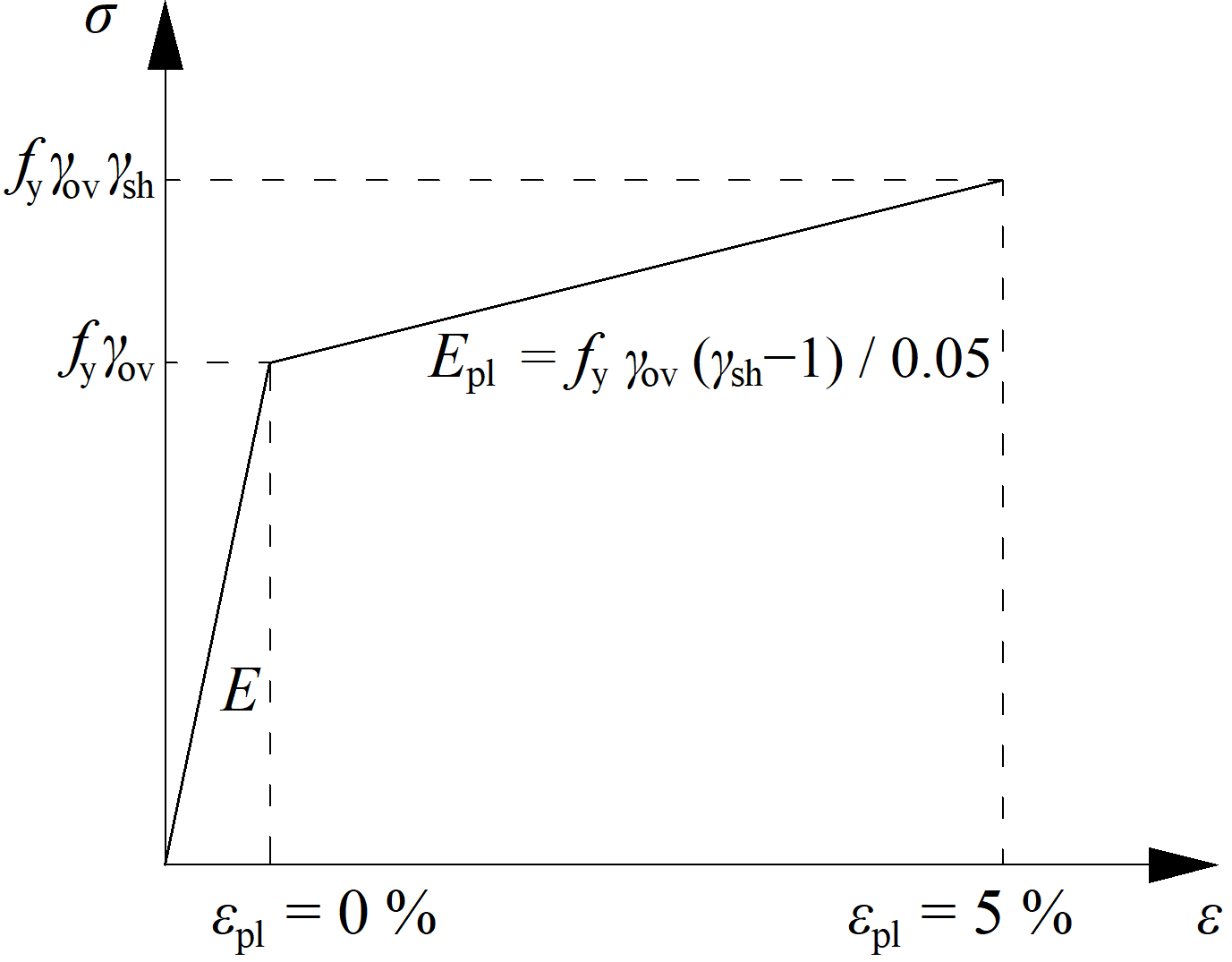
- γsh – strain-hardening factor; the recommended values are γsh = 1.2 for beam in moment resisting frame, γsh = 1.0 otherwise; editable in operation
The material diagram is modified according to the following figure:
The increased strength of the dissipative item allows for the input of loads that cause the plastic hinge to appear in the dissipative item. In the case of moment resisting frame and beam as the dissipative item, the beam should be loaded by My,Ed = γovγshfyWpl,y and corresponding shear forceVz,Ed = –2 My,Ed / Lh, where:
- fy – characteristic yield strength
- Wpl,y – plastic section modulus
- Lh – distance between plastic hinges on the beam
In the case of an asymmetric joint, the beam should be loaded by both sagging and hogging bending moments and their corresponding shear forces.
The plates of dissipative items are excluded from the check.
Buckling analysis (EN)
The load resistance of slender components may be determined by a combination of linear buckling analysis and materially nonlinear analysis.
There are five categories of finite element structural analysis with the following assumptions:
- Linear material, geometrically linear
- Nonlinear material, geometrically linear
- Linear material, linear loss of stability – buckling
- Linear material, geometrically nonlinear using imperfections
- Nonlinear material, geometrically nonlinear using imperfections
A design procedure that combines approaches 2 and 3 – material nonlinearity and stability analysis – is mentioned in Chapter 8 of EN 1993-1-6. The verification of buckling resistance based on the obtained FEM results is described in Annex B of EN 1993-1-5. This procedure is used for a wide range of structures except for very slender shells, where geometrically nonlinear analysis with initial imperfections is more suitable (4 and 5).
The procedure uses load amplifiers α, which are obtained as the results of FEM analysis and allow to predict of the post-buckling resistance of the joints.
The load coefficient, αult,k, is determined by reaching the plastic capacity without considering the geometrical nonlinearity. The check of plastic capacity and the general automatic determination of αult,k is implemented into the developed software.
The critical buckling factor, αcr, is determined, which is obtained using FEM analysis of linear stability. It is determined automatically in the software using the same FEM model as for the calculation of αult,k. It should be noted that the critical point in terms of plastic resistance is not necessarily assessed in the first critical buckling mode. More buckling modes need to be assessed in a complex joint because they are related to different parts of the joint.
The non-dimensional plate slenderness, \( \bar \lambda_p \), of the examined buckling mode is determined:
\[ \bar \lambda_p = \sqrt{\frac{\alpha_{ult,k}}{\alpha_{cr}}} \]
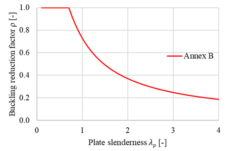
The reduction buckling factor ρ is determined according to Annex B of EN 1993-1-5. The reduction factor depends on the plate slenderness. The used buckling curve shows the influence of the reduction factor on the plate slenderness. The provided buckling factor applicable to non-uniform members is based on the buckling curves of a beam. The verification is based on the von Mises yield criterion and the reduced stress method. Buckling resistance is assessed as
\[ \frac{\alpha_{ult,k} \rho}{\gamma_{M2}} \ge 1 \]
Buckling reduction factor ρ according to EN 1993-1-5 Annex B
Although the process seems trivial, it is general, robust, and easily automated. The advantage of the procedure is the advanced FEM analysis of the whole joint, which can be applied to general geometry. Moreover, it is included in the valid Eurocode standards. The advanced numerical analysis gives a quick overview of the global behavior of the structure and its critical parts and allows fast stiffening to prevent instabilities.
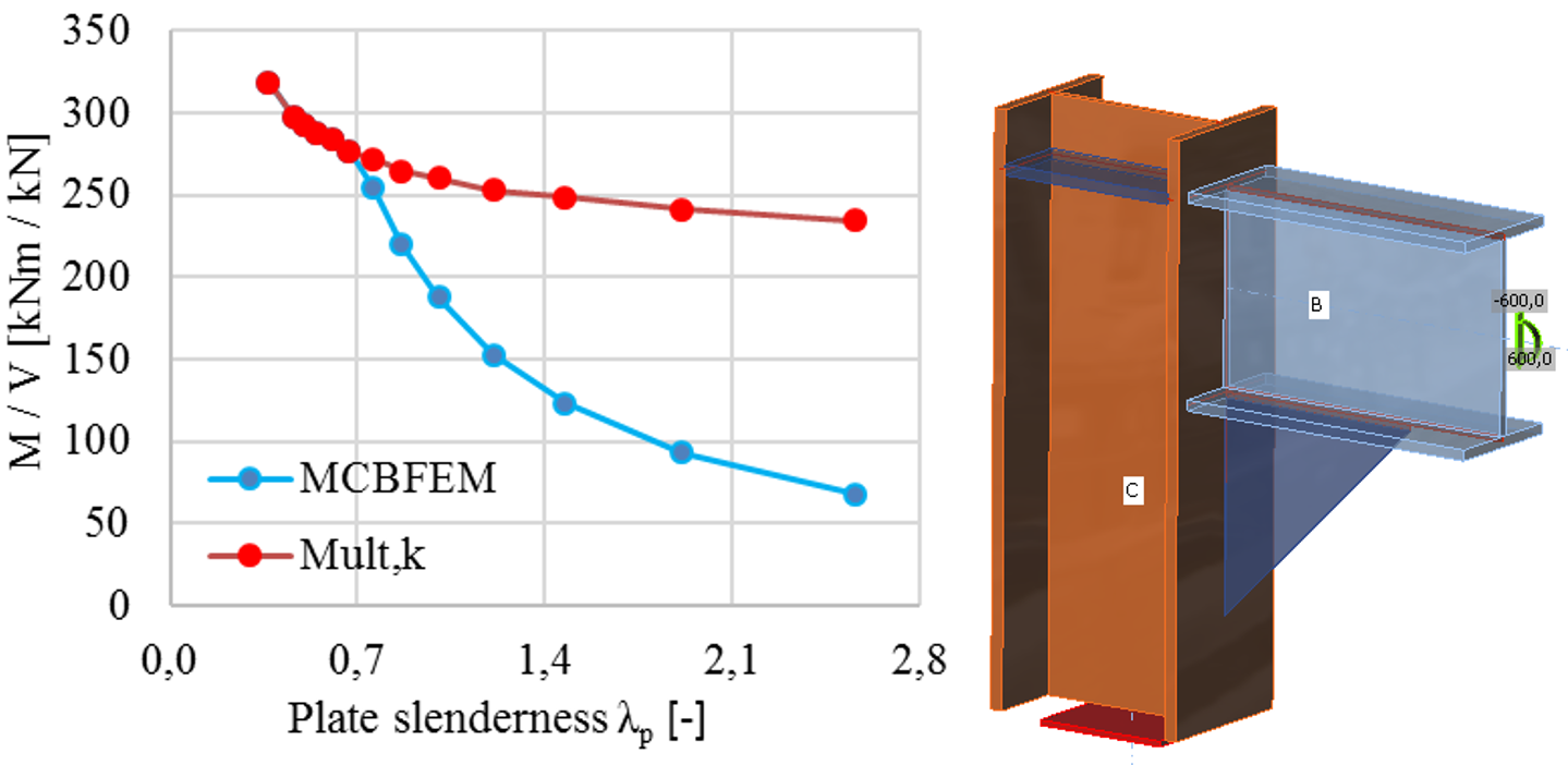
The limit slenderness, λp, is provided in Annex B of EN 1993-1-5 and sets all cases which must be assessed according to the previous procedure. The resistance is limited by buckling for plate slenderness higher than 0.7. With the decreasing slenderness, the resistance is governed by plastic strain. The limit critical buckling factor for plate slenderness equals to 0.7, and buckling resistance equal to the plastic resistance may be obtained as follows
\[ \alpha_{cr} = \frac{\alpha_{ult,k}}{\bar \lambda_p^2} = \frac{1}{0.7^2} = 2.04 \]
The influence of the plate slenderness on the plastic resistance, Mult,k, and buckling resistance, MCBFEM, is shown in the figure below. The diagram shows the results of a numerical study of a triangular stiffener in a portal frame joint.
The influence of plate slenderness on the resistance of portal frame joint with slender stiffener
Joint classification (EN)
Joints are classified according to joint stiffness to:
- Rigid – joints with insignificant change of original angles between members,
- Semirigid – joints which are assumed to have the capacity to furnish a dependable and known degree of flexural restraint,
- Pinned – joints which do not develop bending moments.
Joints are classified according to the EN 1993-1-8 – Cl. 5.2.2.
- Rigid – \( \frac{S_{j,ini} L_b}{E I_b} \ge k_b \)
- Semirigid – \( 0.5 < \frac{S_{j,ini} L_b}{E I_b} < k_b \)
- Pinned – \( \frac{S_{j,ini} L_b}{E I_b} \le 0.5 \)
where:
- Sj,ini – initial stiffness of the joint; the joint stiffness is assumed linear up to the 2/3 of Mj,Rd
- Lb – theoretical length of the analyzed member; set in member properties
- E – Young's modulus of elasticity
- Ib – moment of inertia of the analyzed member
- kb = 8 for frames where the bracing system reduces the horizontal displacement by at least 80 %; kb = 25 for other frames, provided that in every storey Kb/Kc ≥ 0.1. The value of kb = 25 is used unless the user sets "braced system" in Code setup.
- Mj,Rd – joint design moment resistance
- Kb = Ib / Lb
- Kc = Ic / Lc
Horizontal tying
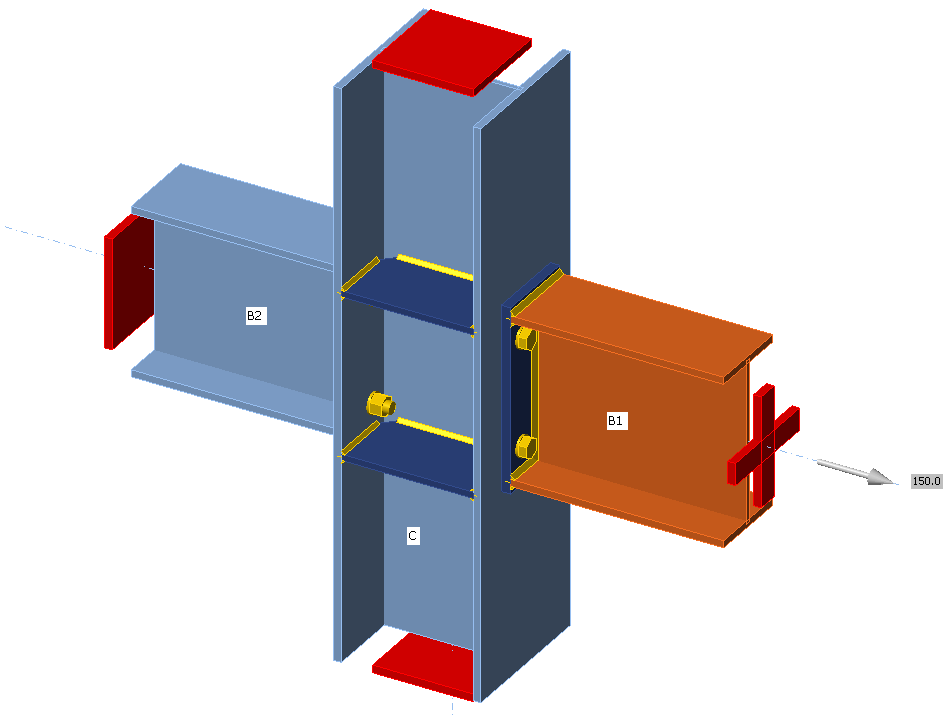
Connections must be designed to transform tensile force that is generated by second-order effects – column is removed and the floor acts as a membrane.
Supports
Only one member is analyzed and all other members are fixed at their ends. Only the normal force should be applied to the analyzed member, so its model type is set to N-Vy-Vz (bending moments and torsion are restricted).
Loading
Normal force acting on the analyzed member should be determined according to EN 1993-1-7, Cl. A.5.1:
For internal ties:
\[T_i=0.8(g_k+\psi q_k) s L \ge 75 \textrm{ kN} \]
For perimeter ties:
\[T_p=0.4(g_k+\psi q_k) s L \ge 75 \textrm{ kN} \]
where:
- \(g_k\) – characteristic permanent loading
- \(q_k\) – characteristic imposed loading
- \(s\) – spacing of ties
- \(L\) – span of the tie
- \(\psi\) – relevant factor in the expression for a combination of action effects for the accidental design situation (i.e. \(\psi_1\) or \(\psi_2\) in accordance with expression (6.11b) of EN 1990).
Material model and checks
According to SCI P358: Joints in steel construction: Simple Joints to Eurocode 3 – Appendix A, the partial safety factor for horizontal tying is introduced, \(\gamma_{Mu}\) with default value 1.1 editable in Code setup. This safety factor is used for plates, bolts, and welds in horizontal tying analysis.
Extreme loads and deformations are expected and the design of plates is based on the ultimate strength of plates, \(f_u\). That is why the material model for finite element analysis behaves elastically up to \(f_u / \gamma_{Mu}\). The slope of the plastic branch is Young's modulus of elasticity \(E/1000\). Check is performed for 5% plastic strain limit.
The resistances of bolts and welds are calculated with \(\gamma_{Mu}\) instead of \(\gamma_{M2}\). When using the default values of partial safety factors, the load resistances are higher by about 14 % than for the ultimate limit state.
Preloaded bolts are assumed to slip and they are checked as regular, snug-tight bolts.
References
EN 1993-1-7: Eurocode 1 – Actions on structures – Part 1-7: General actions – Accidental actions, CEN, 2006.
SCI P358: Joints in steel construction: Simple Joints to Eurocode 3

