Verifica delle componenti della connessione in acciaio (EN)
Il metodo CBFEM combina i vantaggi del metodo generale degli elementi finiti (FEM) e del metodo standard delle componenti (CM). Le sollecitazioni e le forze interne calcolate sul modello CBFEM accurato vengono utilizzate per le verifiche di tutte le componenti.
Le singole componenti sono verificate in base all'Eurocodice EN 1993-1-8.
Verifica delle piastre secondo codice EN (Eurocodice)
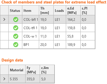
Le sollecitazioni equivalenti (Huber-Mises-Hencky - HMH, von Mises) e le deformazioni plastiche risultanti sono calcolate sulle piastre. Per le piastre in acciaio si utilizza il modello elasto-plastico del materiale. Viene eseguita una verifica della deformazione plastica equivalente. Il valore limite del 5% è suggerito dall'Eurocodice (EN 1993-1-5, app. C, par. C8, nota 1); questo valore può essere modificato dall'utente nella configurazione del Codice.
L'elemento piastra è diviso lungo il suo spessore in cinque strati di elementi finiti shells e il comportamento elastico/plastico è studiato in ogni strato separatamente. Il riassunto dell'output della verifica mostra la verifica più critica di tutti e cinque gli strati.
Il metodo CBFEM può fornire tensioni superiori al limite di snervamento. Il motivo è la leggera inclinazione del ramo plastico del diagramma sforzo-deformazione, utilizzato nell'analisi per migliorare la stabilità del calcolo dell'interazione. Questo non è un problema per la progettazione pratica. A carichi più elevati, la deformazione plastica equivalente aumenta e il giunto cede superando il limite di deformazione plastica.
Verifiche delle saldature secondo codice (EN)
Le saldature a cordoni d'angolo sono verificate in base all'EN 1993-1-8. La resistenza delle saldature di testa si presume uguale a quella del metallo di base e non viene verificata.
Saldature ad angolo
Saldature a cordoni d'angolo
Resistenza di progetto
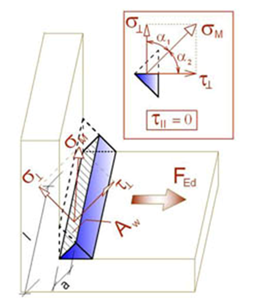
La ridistribuzione plastica nelle saldature è utilizzata per evitare automaticamente le singolarità di sollecitazione negli elementi di saldatura e ridistribuire le sollecitazioni lungo la lunghezza della saldatura. La resistenza della saldatura corrisponde approssimativamente al calcolo manuale e le sollecitazioni sono distribuite correttamente per questioni complesse come la saldatura su una flangia non rigida (EN 1993-1-8 - Cl. 4.10). La sollecitazione nella sezione di gola di una saldatura ad angolo è determinata in conformità alla norma EN 1993-1-8 Cl. 4.5.3. Le sollecitazioni sono calcolate a partire dalle sollecitazioni nell'elemento di saldatura. Il momento flettente attorno all'asse longitudinale della saldatura non è considerato.
\[ \sigma_{w,Ed}=\sqrt{\sigma_{\perp}^2 + 3 \left ( \tau_{\perp}^2 + \tau_{\parallel}^2 \right )} \]
\[ \sigma_{w,Rd} = \frac{f_u}{\beta_w \gamma_{M2}} \]
Utilizzo delle saldature
\[ U_t = \min \left\{ \frac{\sigma_{{w,Ed}}}{\sigma_{w,Rd}}, \frac{\sigma_{\perp}}{0.9 f_u / {\gamma_{M2}}} \right\} \]
dove:
- σw,Ed – sollecitazione equivalente nella saldatura
- σw,Rd – resistenza di saldatura
- βw – fattore di correlazione (EN 1993-1-8 - Tabella 4.1)
- fu – resistenza ultima, scelta come la più bassa tra i due materiali di base collegati o secondo il materiale scelto dall'utente
- γM2 – fattore di sicurezza (EN 1993-1-8 - Tabella 2.1; editabile in Impostazione codice)
- σ┴, τ┴, τ‖ – sollecitazioni nella weld secondo la seguente figura:
Tutti i valori richiesti per la verifica sono indicati nelle tabelle. Ut è l'utilizzo dell'elemento più sollecitato. L'utilizzo della ridistribuzione plastica delle sollecitazioni nella saldatura è decisivo. Utc fornisce informazioni sull'utilizzo lungo la lunghezza della saldatura. È il rapporto tra la sollecitazione effettiva in tutti gli elementi della saldatura e la resistenza di progetto della sollecitazione dell'intera lunghezza della saldatura.
La tensione equivalente nel diagramma di saldatura mostra la seguente sollecitazione:
\[ \sigma = \max \left \{ \frac{\sigma_{\perp}}{0.9 \beta_w}, \, \sqrt{\sigma_{\perp}^2 + 3 \tau_{\perp}^2 + 3 \tau_{\parallel}^2} \right \} \]
Saldature di testa
Le saldature possono essere specificate come saldature di testa. La penetrazione completa del giunto è considerata per le saldature di testa e pertanto tali saldature non vengono verificate.
Dettagli
Lo spessore minimo delle piastre delle connessioni saldate è verificato in conformità alla norma EN 1993-1-8 - 4.1(1):
- Per le sezioni cave di acciaio, lo spessore della piastra deve essere di almeno 2.5 mm
- Per le altre piastre, lo spessore della piastra deve essere di almeno 4 mm
Lo spessore massimo della gola della saldatura delle saldature d'angolo viene controllato per piastre parallele. Viene emesso un errore, tale saldatura non è fattibile a causa di vincoli geometrici.
Lo spessore minimo della gola delle saldature d'angolo deve essere di almeno 3 mm secondo EN 1993-1-8 – 4.5.2(2). Viene emesso un errore quando questo requisito non è soddisfatto.
Viene emesso un avvertimento quando lo spessore della gola di saldatura è inferiore ai requisiti della norma DIN EN 1993-1-8 – NA fino a 4.5.2:
\[a \le \sqrt{t_{max}}-0.5\]
dove:
- \(a\) – altezza di gola della saldatura
- \(t_{max}\) – spessore della piastra collegata più spessa
- le unità di misura devono essere in [mm]
Le informazioni sono fornite quando l'altezza di gola della saldatura è inferiore rispetto al requisito di duttilità minima dei giunti saldati ai sensi del FprEN 1993-1-8:2023 - 6.9(4). Tale requisito è verificato per le saldature ad angolo bilaterali da:
\[a/t=\frac{\beta_w\gamma_{M2} f_y}{\sqrt{2} f_u \gamma_{M0} } \cdot \min \left \{1.0, 1.1\frac{f_y}{f_u} \right \}\]
dove:
- \(a\) – altezza di gola della saldatura
- \(t\) – spessore della piastra collegata lungo il bordo
- \(\beta_w\) – fattore di correlazione della saldatura
- \(\gamma_{M2}\) – fattore di sicurezza per bulloni e saldature; editabile in Impostazione codice
- \(f_y\) – resistenza limite della piastra
- \(f_u\) – resistenza ultima della saldatur
- \(\gamma_{M0}\) – fattore di sicurezza per le piastre; editabile in Impostazione codice
L'altezza di gola della saldatura ad angolo unilaterale è due volte superiore a quella della saldatura ad angolo bilaterale.
Verifica dei bulloni e dei bulloni precaricati secondo Eurocodice (EN)
Bulloni
La rigidezza iniziale e la resistenza di progetto dei bulloni a taglio sono indicate nel CBFEM redatto sulla base del Cl. 3.6 e 6.3.2 nella norma EN 1993-1-8. La molla, che rappresenta il carico e la trazione, ha un comportamento forza-deformazione bi-lineare con una rigidezza iniziale e una resistenza di progetto in accordo alla Cl. 3.6 e 6.3.2 nella norma EN 1993-1-8.
Resistenza di progetto del bullone a trazione (EN 1993-1-8 - Tabella 3.4):
\[ F_{t,Rd}=0.9 f_{ub} A_s / \gamma_{M2} \]
Resistenza di progetto a taglio mediante punzonamento della testa del bullone o del dado (EN 1993-1-8 - Tabella 3.4):
\[ B_{p,Rd} = 0.6 \pi d_m t_p f_u / \gamma_{M2} \]
Resistenza di progetto a taglio per un piano di taglio (EN 1993-1-8 - Tabella 3.4):
\[ F_{v,Rd} = \alpha_v f_{ub} A_s / \gamma_{M2} \]
La resistenza di progetto a taglio può essere moltiplicata per il fattore di riduzione βp se è presente un'imbottitura (EN 1993-1-8 - Cl.). 3.6.1. (12)) e questa opzione è selezionata in Impostazione codice.
Resistenza di progetto a rifollamento di una piastra (EN 1993-1-8 - Tabella 3.4):
\( F_{b,Rd} = k_1 \alpha_b f_u d t / \gamma_{M2} \) per fori standard
\( F_{b,Rd} = 0.6 k_1 \alpha_b f_u d t / \gamma_{M2} \) per fori asolati
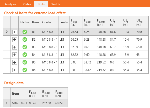
Utilizzo in trazione [%]:
\[ Ut_t = \frac{F_{t,Ed}}{\min (F_{t,Rd},\, B_{p,Rd})} \]
Utilizzo a taglio [%]:
\[ Ut_s = \frac{F_{v,Ed}}{\min (F_{v,Rd},\, F_{b,Rd})} \]
Interazione al taglio e trazione [%]:
\[ Ut_{ts}=\frac{F_{v,Ed}}{F_{v,Rd}}+\frac{F_{t,Ed}}{1.4 F_{t,Rd}} \]
dove:
- As – area del bullone sollecitata a trazione
- fub – resistenza ultima del bullone a trazione
- dm – media delle distanze piane tra i punti e le larghezze della testa del bullone o del dado, a seconda della più piccola
- d – diametro del bullone
- tp – spessore della piastra sotto la testa del bullone/dado
- fu – resistenza ultima dell'acciaio
- αv = 0.6 per classi 4.6, 5.6, 8.8 e 0.5 per classi 4.8, 5.8, 6.8, 10.9
- \( k_1 = \min \left \{2.8 \frac{e_2}{d_0}-1.7, \, 1.4 \frac{p_2}{d_0}-1.7, \, 2.5 \right \} \) – coefficiente indicato nella Tabella 3.4
- \(\alpha_b = 1.0\) se la verifica in bearing con \(\alpha_b\) è disattivata in Impostazione codice; se la verifica è attiva, il valore di αb è determinato secondo la EN 1993-1-8 – Tabella 3.4: \( \alpha_b = \min \left \{ \alpha_d, \, \frac{f_{ub}}{f_u}, \, 1.0 \right \} \)
- \(\alpha_d = \min \left \{ \frac{e_1}{3 d_0}, \, \frac{p_1}{3 d_0}-\frac{1}{4} \right \} \)
- e1, e2 – distanze dal bordo nella direzione del carico e perpendicolari al carico
- p1, p2 – passi dei bulloni nella direzione del carico e perpendicolari al carico
- Ft,Ed – forza di progetto a trazione nel bullone
- Fv,Ed – forza di taglio di progetto nel bullone
- γM2 – coefficiente di sicurezza (EN 1993-1-8 – Tabella 2.1; modificabile in Impostazione codice)
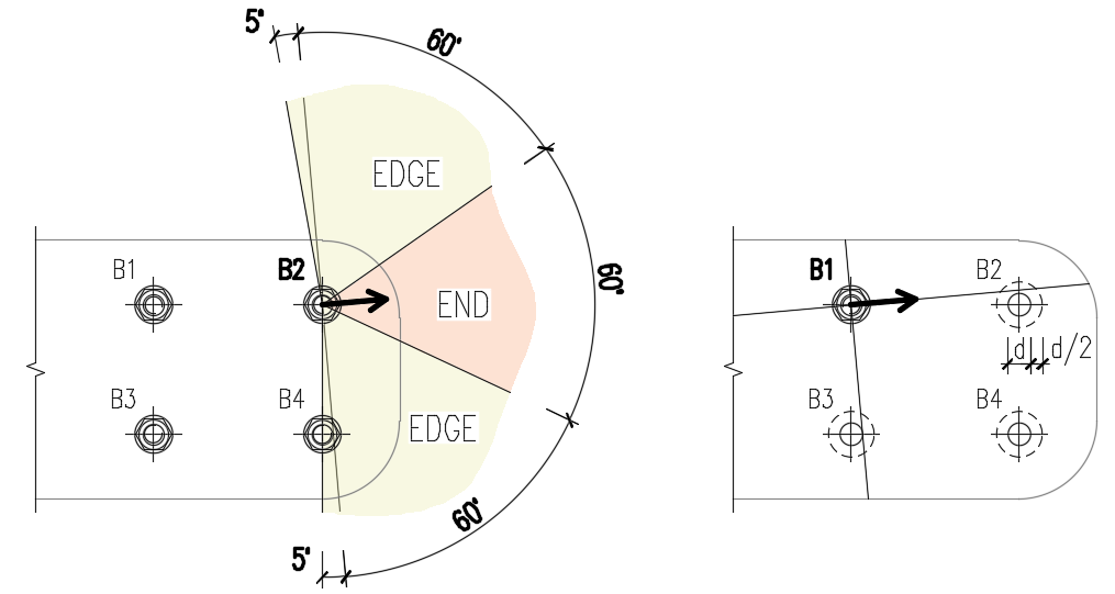
Le distanze dai bordi utilizzate per la resistenza (bearing resistance) dei bulloni devono essere rilevante per le geometrie generali delle piastre, per le piastre con aperture, per le sagome, ecc.
L'algoritmo legge la direzione reale del vettore della forza di taglio risultante in un dato bullone e, successivamente, calcola le distanze necessarie per la verifica (bearing check).
Le distanze dall'estremità (e1) e dal bordo (e2) sono determinate dividendo il contorno della piastra in tre segmenti. Il segmento di estremità è indicato da un angolo di 60° nella direzione del vettore della forza. I segmenti di bordo sono definiti da due angoli di 65° perpendicolari al vettore di forza. La distanza più breve tra un bullone e un segmento rilevante è considerata, quindi, come una distanza di estremità o di bordo.
Le distanze tra i fori dei bulloni (p1; p2) sono determinate allargando virtualmente i fori dei bulloni circostanti per metà del loro diametro e, successivamente, tracciando due linee, una parallela e una perpendicolare, al vettore della forza di taglio. Le distanze dai fori dei bulloni allargati che sono intersecati da queste linee sono quindi considerate nel calcolo come p1 e p2.
Bulloni che collegano piastre sottili
Per i bulloni che collegano piastre di spessore inferiore a 3 mm, si applicano invece le disposizioni della norma EN 1993-1-3, Tabella 8.4.
Resistenza di progetto a rifollamento della piastra
\[F_{b,Rd}=2.5\cdot \alpha_b \cdot k_t \cdot f_u \cdot d \cdot t /\gamma_{M2}\]
dove:
- \( \alpha_b=\min \left \{ 1.0, e_1/(3d) \right \} \)
- \(k_t = (0.8 t+1.5)/2.5 \) for 0.75 mm \(\le t \le\) 1.25 mm; \( k_t=1.0 \) for \(t>1.25\) mm
- \(f_u\) – resistenza ultima della piastra collegata
- \(d\) – diametro del bullone
- \(t\) – spessore della piastra collegata
- \(\gamma_{M2}\) – coefficiente di sicurezza parziale per i collegamenti, editabile in Impostazione codice; valore predefinito \(\gamma_{M2}=1.25\)
La resistenza a taglio, la resistenza a trazione, l'interazione di trazione e di taglio e la resistenza a taglio mediante rifollamento sono determinate in base alla norma EN 1993-1-8 - ugualmente ai bulloni che collegano piastre con uno spessore superiore a 3 mm.
Intervallo di validità:
\[e_1 \ge 1.0 d_0 \]
\[p_1 \ge 3 d_0 \]
\[e_2 \ge 1.5 d_0 \]
\[p_2 \ge 3 d_0 \]
\[ f_u \le 550 \textrm{ MPa} \]
\[3 \textrm{ mm} > t \ge 0.75 \textrm{ mm} \]
Dimensione minima dei bulloni: M6 – verificata come \(d \ge 6\) mm
Classe di resistenza dei bulloni: 4.6 – 10.9 – verificata come \(f_u \le 1000\) MPa
I bulloni saranno contrassegnati come non verificati se non rientreranno nell'intervallo di validità.
Bulloni precaricati
Resistenza di progetto a scorrimento per bulloni di classe 8.8 o 10.9 (EN 1993-1-8, Cl. 3.9 - Equazione 3.8):
\[ F_{s,Rd} =\frac{k_s n \mu (F_{p,C} - 0.8 F_{t,Ed})}{\gamma_{M3}} \]
Il precarico (EN 1993-1-8 – Equazione 3.7)
Fp,C = 0.7 fub As
Il fattore di precarico 0,7 può essere modificato in Impostazione codice.
Utilizzo [%]:
\[ Ut_s = \frac{V}{F_{s,Rd}} \]
dove:
- As – area del bullone sollecitata a trazione
- fub – resistenza ultima a trazione
- ks – coefficiente (EN 1993-1-8 – Tabella 3.6; ks = 1 per i fori tondi normali, ks = 0.63 per i fori asolati)
- μ – coefficiente di scorrimento modificabile in Impostazione codice (EN 1993-1-8 – Tabella 3.7)
- n – numero delle superfici di attrito. La verifica è calcolata separatamente per ogni superficie di attrito.
- γM3 – coefficiente di sicurezza (EN 1993-1-8 - Tabella 2.1; editabile in Impostazione codice - i valori raccomandati di progetto sono 1,25 per lo stato limite ultimo e 1,1 per lo stato limite di esercizio)
- V – forza di taglio di progetto nel bullone
- Ft,Ed – forza di trazione di progetto nel bullone
Se lo scorrimento dei bulloni precaricati viene verificato per lo stato limite di esercizio, questi devono essere successivamente commutati in "interazione trazione/taglio" e verificati per lo stato limite ultimo.
Resistenza di progetto al fuoco
Si presume che i bulloni precaricati slittino, per cui le verifiche dei bulloni portanti e dei bulloni precaricati sono le stesse.
Sono eseguite sia verifiche al fuoco sia a temperatura ambiente e il valore minimo viene scelto come resistenza al carico di progetto.
A temperatura elevata, i bulloni sono verificati secondo la norma EN 1993-1-2, Allegato D. Si noti che l'area ridotta dalla filettatura è sempre utilizzata per la verifica a taglio secondo il punto D1.1.1.
Dettagli
Le verifiche dei dettagli dei bulloni sono eseguiti se l'opzione è selezionata in impostazione codice. Sono verificate le distanze dal centro del bullone ai bordi della piastra e tra i bulloni. Le distanze raccomandate dai bordi e = 1,2 e tra i bulloni p = 2,2 sono indicate nella Tabella 3.3 secondo la norma EN 1993-1-8. L'utente può modificare entrambi i valori in Impostazione codice.
È controllato lo spessore minimo delle piastre collegate da bulloni. Lo spessore delle piastre deve essere superiore a 0,75 mm in conformità alla norma EN 1993-1-3 - Tabella 8.4.
Le informazioni sono fornite quando i requisiti di duttilità e di capacità di rotazione per il collegamento bullonato in trazione non sono soddisfatti, in conformità alla norma EN 1993-1-8 - 6.4.2. Se il bullone è caricato prevalentemente in trazione, la piastra collegata più sottile dovrebbe soddisfare tali requisiti:
\[t \le 0,36d \sqrt{\frac{f_{ub}}{f_y}}\]
Le dimensioni predefinite dei gruppi di bulloni sono stabilite in conformità alle norme EN ISO 4014 - Teste di bulloni esagonali; EN ISO 4032 - Dadi esagonali regolari; EN ISO 7089 - Rondelle piane - Serie normale - Grado prodotto A.
Verifica degli ancoraggi secondo Eurocodice (EN)
The Bulloni di ancoraggio resistances are evaluated according to EN 1992-4, Cl. 7.2 for headed and post-installed anchors. Pull-out failure of straight anchors, combined pull-out and concrete failure of bonded anchors, and concrete splitting failure are not checked due to missing information available only for the particular anchor and glue type from the anchor manufacturer.
In the Code setup, settings are available to activate/deactivate concrete cone breakout checks in tension and shear. If the concrete cone breakout check is not activated, it is assumed that the dedicated reinforcement is designed to resist the force. The magnitude of the force is provided in formulas. Furthermore, the concrete can be set as cracked or uncracked. The resistances of uncracked concrete are higher.
Le resistenze dei bulloni di ancoraggio sono valutate in conformità alla norma EN 1992-4, Cl. 7.2 per ancoraggi gettati in opera e post-installati. Il cedimento per estrazione (pull-out) degli ancoraggi dritti, il cedimento combinato per estrazione e degrado del calcestruzzo degli ancoraggi incollati e il cedimento per spacco (splitting) del calcestruzzo non sono stati verificati unicamente a causa della mancanza di informazioni disponibili per i tipi particolari di ancoraggio e di colla utilizzati dal produttore dell'ancoraggio.
In Configurazione codice sono disponibili le impostazioni per attivare/disattivare le verifiche di rottura del cono di calcestruzzo per trazione e taglio. Se la verifica di rottura del cono di calcestruzzo non è attivata, si presume che la relativa armatura sia progettata per resistere a tale forza. L'entità della forza è fornita in formule. Inoltre, il calcestruzzo può essere posto in opera come fessurato o non fessurato. La resistenza del calcestruzzo non fessurato è più elevata.
Resistenza dell'acciaio a trazione (EN 1992-4, Cl. 7.2.1.3):
Tensile steel resistance (EN 1992-4, Cl. 7.2.1.3):
\[ N_{Rd,s} = \frac{N_{Rk,s}}{\gamma_{Ms}} \]
where:
- NRk,s = c ∙ As ∙ fuk – characteristic resistance of a fastener in case of steel failure
- c – decrease in tensile resistance of bolts with cut thread according to EN 1993-1-8 – Cl. 3.6.1. (3) editable in Code setup
- As – anchor bolt tensile stress area
- fuk – anchor bolt characteristic ultimate tensile strength
- \(\gamma_{Ms}=1.2 \cdot \frac{f_{uk}}{f_{yk}} \ge 1.4\) – partial safety factor for steel failure in tension (EN 1992-4, Table 4.1)
- fyk – anchor bolt characteristic yield strength
Concrete cone failure resistance of anchor or group of anchors (EN 1992-4, Cl. 7.2.1.4):
\[ N_{Rd,c} = \frac{N_{Rk,c}}{\gamma_{Mc}} \]
where:
- \(N_{Rk,c}=N_{Rk,c}^0 \cdot \frac{A_{c,N}}{A_{c,N}^0} \cdot \psi_{s,N} \cdot \psi_{re,N} \cdot \psi_{ec,N} \cdot \psi_{M,N}\) – characteristic resistance of a fastener, a group of fasteners and the tensioned fasteners of a group of fasteners in case of concrete cone failure
- \(N_{Rk,c}^0 = k_1 \sqrt{f_{ck}} h_{ef}^{1.5}\) – characteristic resistance of a single fastener placed in concrete and not influenced by adjacent fasteners or edges of the concrete member
- k1 – factor taking into account concrete condition and anchor type; for cast-in headed anchors (with washer plates) k1 = 8.9 for cracked concrete and k1 = 12.7 for non-cracked concrete; for post-installed fasteners (straight anchors) k1 = 7.7 for cracked concrete and k1 = 11.0 for non-cracked concrete
- fck – characteristic concrete compressive cylinder strength
- hef – embedment depth of the anchor in concrete; for three or more close edges, EN 1992-4, Cl. 7.2.1.4 (8) applies and effective \(h'_{ef} = \max \left \{ \frac{c_{max}}{c_{cr,N}} \cdot h_{ef}, \, \frac{s_{max}}{s_{cr,N}} \cdot h_{ef} \right \}\) is used instead in formulas for NRk,c0, ccr,N, scr,N, Ac,N, Ac,N0, ψs,N, and ψec,N
- Ac,N – actual projected area, limited by overlapping concrete cones of adjacent fasteners as well as by edges of the concrete member
- Ac,N0 = scr,N2 – reference projected area, i.e. area of concrete of an individual anchor with large spacing and edge distance at the concrete surface
- \(\psi_{s,N}=0.7+0.3 \cdot \frac{c}{c_{cr,N}} \le 1\) – factor taking into account disturbance of the distribution of stresses in the concrete due to the proximity of an edge of the concrete member
- c – smallest edge distance
- ccr,N = 1.5 ∙ hef – characteristic edge distance for ensuring the transmission of the characteristic resistance of an anchor in case of concrete break-out under tension loading
- \(\psi_{re,N}=0.5+\frac{h_{ef}}{200} \le 1\) – shell spalling factor
- \(\psi_{ec,N}=\frac{1}{1+2 \cdot (e_N / s_{cr,N})} \le 1\) – factor taking into account group effect when different tension loads are acting on the individual fasteners of a group; ψec,N is determined separately for each direction and the product of both factors is used
- eN – eccentricity of resultant tension force of tensioned fasteners in respect to the center of gravity of the tensioned fasteners
- scr,N = 2 ∙ ccr,N – characteristic spacing of anchors to ensure the characteristic resistance of the anchors in case of concrete cone failure under tension load
- \(\psi_{M,N} = 2- \frac{z}{1.5 \cdot h_{ef}} \ge 1\) – factor taking into account effect of a compression force between fixture and concrete in cases of bending moments with or without axial force; this parameter is equal to 1 if c < 1.5 hef or the ratio of the compressive force (including the compression due to bending) to the sum of tensile forces in anchors is smaller than 0.8 or z / hef ≥ 1.5
- z – internal lever arm of a fastening
- γMc = γc ∙ γinst – partial safety factor (EN 1992-4, Table 4.1)
- γc – partial safety factor for concrete (editable in Code setup)
- γinst – partial safety factor taking account of the installation safety of an anchor system (editable in Code setup)
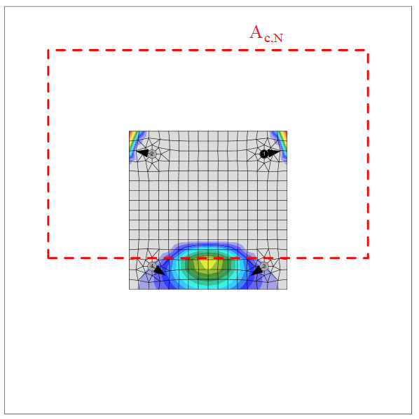
The concrete breakout cone area for a group of anchors loaded by tension that creates a common concrete cone, Ac,N, is shown by the red dashed line.
Pull-out resistance (EN 1992-4, Cl. 7.2.1.5)
Pull-out resistance is checked for anchors with washer plates according to EN 1992-4, Cl. 7.2.1.5:
\[ N_{Rd,p}=\frac{N_{Rk,p}}{\gamma_{Mc}} \]
where:
- NRk,p = k2 ∙ Ah ∙ fck – characteristic resistance in case of pull-out failure
- k2 – coefficient dependent on concrete condition, k2 = 7.5 for cracked concrete, k2 = 10.5 for non-cracked concrete
- Ah – bearing area of head of anchor; for circular washer plate \(A_h = \frac{\pi}{4} \left ( d_h^2 - d^2 \right )\), for rectangular washer plate \(A_h = a_{wp}^2 - \frac{\pi}{4} d^2\)
- dh ≤ 6 th + d – diameter of the head of the fastener
- th – thickness of the head of the headed fastener
- d – diameter of the shank of the fastener
- fck – characteristic concrete compressive cylinder strength
- γMc = γc ∙ γinst – partial safety factor (EN 1992-4, Table 4.1)
- γc – partial safety factor for concrete (editable in Code setup)
- γinst – partial safety factor taking account of the installation safety of an anchor system (editable in Code setup)
The pullout resistance of other types of anchors is not checked and must be guaranteed by the manufacturer.
Concrete blowout resistance (EN 1992-4, Cl. 7.2.1.8)
Blow-out failure is checked for headed anchors (Anchor type – washer) with edge distance c ≤ 0.5 hef according to EN 1992-4, Cl. 7.2.1.8. Anchors are treated as a group if their spacing near the edge is s ≤ 4 c1. Undercut anchors can be checked the same way but the value of Ah is unknown in the software. The blow-out failure of undercut anchors can be determined by selecting a washer plate with the corresponding dimension.
\[N_{Rd,cb} = \frac{N_{Rk,cb}}{\gamma_{Mc}}\]
where:
- \(N_{Rk,cb} = N_{Rk,cb}^0 \cdot \frac{A_{c,Nb}}{A_{c,Nb}^0} \cdot \psi_{s,Nb} \cdot \psi_{g,Nb} \cdot \psi_{ec,Nb}\) – characteristic resistance in case of concrete blow-out failure
- \(N_{Rk,cb}^0 = k_5 \cdot c_1 \cdot \sqrt{A_h} \cdot \sqrt{f_{ck}}\) – characteristic resistance of a single fastener, not influenced by adjacent fasteners or further edges
- Ac,Nb – actual projected area, limited by overlapping concrete break-out bodies of adjacent fasteners as well as by proximity of edges of the concrete member or the member thickness
- Ac,Nb0 = (4 c1)2 – reference projected area of a single fastener with an edge distance equal to c1
- \(\psi_{s,Nb} = 0.7+0.3 \frac{c_2}{2 c_1} \le 1\) – factor taking into account the disturbance of the distribution of stresses in the concrete due to the proximity of a corner of the concrete member
- \( \psi_{g,Nb} = \sqrt{n} + (1-\sqrt{n}) \frac{s_2}{4c_1} \ge 1 \) – factor taking into account group effect
- \(\psi_{ec,Nb} = \frac{1}{1+2 e_N / s_{cr,Nb}} \le 1\) – factor taking into account group effect, when different loads are acting on the individual fasteners of a group
- k5 – parameter related to the state of the concrete; for cracked concrete k5 = 8.7, for uncracked concrete k5 = 12.2
- c1 – edge distance of fastener in direction 1 towards the closest edge
- c2 – edge distance of fastener perpendicular to direction 1 that is the smallest edge distance in a narrow member with multiple edge distances
- Ah – area of the load-bearing head of the fastener; for circular washer plate \(A_h = \frac{\pi}{4} \left ( d_h^2 - d^2 \right )\), for rectangular washer plate \(A_h = a_{wp}^2 - \frac{\pi}{4} d^2\)
- d – anchor nominal diameter
- dh – circular washer plate diameter
- awp – side size of squared washer plate
- fck – characteristic compressive cylinder strength of concrete
- n – number of fasteners in a row parallel to the edge of the concrete member
- s2 – spacing of fasteners in a group perpendicular to direction 1
- scr,Nb = 4 c1 – spacing that is required for a fastener to develop its characteristic tensile strength against blow-out failure
Anchor shear steel resistance (EN 1992-4 – Cl. 7.2.2.3)
Anchor shear steel resistance is checked according to EN 1992-4 – Cl. 7.2.2.3. Friction is not taken into account. Shear with and without lever arm is recognized in dependence on base plate manufacturing operation settings.
\[V_{Rd,s} = \frac{V_{Rk,s}}{\gamma_{Ms}}\]
For stand-off: direct, the shear without lever arm is assumed (EN 1992-4 – Cl. 7.2.2.3.1):
VRk,s = k6 ∙ As ∙ fuk – characteristic resistance of a single fastener in case of steel failure; or fasteners with a ratio hef / dnom < 5 and a concrete compressive strength class < C20/25 the characteristic resistance VRk,s should be multiplied by a factor of 0.8.
For stand-off: mortar joint, the shear with lever arm is assumed (EN 1992-4 – Cl. 7.2.2.3.2):
\[V_{Rk,s}= \frac{\alpha_M \cdot M_{Rk,s}}{l_a}\]
where:
- k6 = 0.6 for anchors with fuk ≤ 500 MPa; k6 = 0.5 otherwise
- As – shear area of anchor; if shear plane in a thread is selected, the area reduced by threads is used; otherwise, full shank area is used
- fuk – anchor bolt ultimate strength
- αM = 2 – full restraint is assumed (EN 1992-4 – Cl. 6.2.2.3)
- \( M_{Rk,s} = M_{Rk,s}^0 \left ( 1 - \frac{N_{Ed}}{N_{Rd,s}} \right ) \) – characteristic bending resistance of the anchor decreased by the tensile force in the anchor
- MRk,s0 = 1.2 Wel fub – characteristic bending resistance of the anchor (ETAG 001, Annex C – Equation (5.5b))
- \( W_{el} = \frac{\pi d^3}{32}\) – section modulus of the anchor
- d – anchor bolt diameter; if the shear plane in a thread is selected, the diameter reduced by threads is used; otherwise, nominal diameter, dnom, is used
- NEd – tensile force in the anchor
- NRd,s – tensile resistance of the anchor
- la = 0.5 dnom + tmortar + 0.5 tbp – lever arm
- tmortar – thickness of mortar (grout)
- tbp – thickness of the base plate
- γMs = 1.0 ∙ fuk / fyk ≥ 1.25 for fuk ≤ 800 MPa and fyk / fuk ≤ 0.8; γMs = 1.5 otherwise – partial safety factor for steel failure (EN 1992-4 – Table 4.1)
Concrete pry-out failure (EN 1992-4 – Cl. 7.2.2.4):
\[ V_{Rd,cp}= \frac{V_{Rk,cp}}{\gamma_{Mc}} \]
where:
- VRk,cp = k8 ∙ NRk,c – characteristic resistance of concrete pry-out failure
- k8 = 1 for hef < 60 mm; k8 = 2 for hef ≥ 60 mm (ETAG 001, Annex C – Cl. 5.2.3.3)
- NRk,c – characteristic resistance of a fastener, a group of fasteners, and the tensioned fasteners of a group of fasteners in case of concrete cone failure; all anchors are assumed to be in tension
- γMc = γc – partial safety factor (EN 1992-4 – Table 4.1, γinst = 1.0 for shear loading)
- γc – partial safety factor for concrete (editable in Code setup)
Concrete edge failure (EN 1992-4 – Cl. 7.2.2.5):
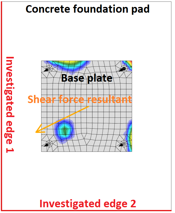
Concrete edge failure is a brittle failure, and the worst possible case is checked, i.e. only the anchors located near the edge transfer the full shear load acting on a whole base plate. If anchors are positioned in a rectangular pattern, the row of anchors at the investigated edge transfers the shear load. If anchors are positioned irregularly, the two anchors nearest to the investigated edge transfer the shear load. Two edges in the direction of the shear load are investigated, and the worst case is shown in the results.
Investigated edges in dependence on the direction of the shear force resultant
\[ V_{Rd,c} = \frac{V_{Rk,c}}{\gamma_{Mc}} \]
where:
- \( V_{Rk,c}= V_{Rk,c}^0 \cdot \frac{A_{c,V}}{A_{c,V}^0} \cdot \psi_{s,V} \cdot \psi_{h,V} \cdot \psi_{ec,V} \cdot \psi_{\alpha,V} \cdot \psi_{re,V} \) – characteristic resistance of a fastener or a group of fasteners loaded towards the edge
- \( V_{Rk,c}^0 = k_9 \cdot d_{nom}^\alpha \cdot l_f^\beta \cdot f_{ck}^{0.5} \cdot c_1^{1.5}\) – initial value of the characteristic resistance of a fastener loaded perpendicular to the edge
- k9 – factor taking into account concrete condition; k9 = 1.7 for cracked concrete, k9 = 2.4 for non-cracked concrete
- \( \alpha = 0.1 \left ( \frac{l_f}{c_1} \right ) ^{0.5} \)
- \( \beta = 0.1 \left ( \frac{d_{nom}}{c_1} \right ) ^{0.2} \)
- lf = min (hef, 12 dnom) for dnom ≤ 24 mm; lf = min [hef, max (8 dnom, 300 mm)] for dnom > 24 mm – effective length of the anchor in shear
- hef – embedment depth of the anchor in concrete
- c1 – distance from the anchor to the investigated edge; for fastenings in a narrow, thin member, the effective distance \( c'_1=\max \left \{ \frac{c_{2,max}}{1.5}, \, \frac{h}{1.5}, \, \frac{s_{2,max}}{3} \right \} \) is used instead
- c2 – smaller distance to the concrete edge perpendicular to the distance c1
- dnom – nominal anchor diameter
- Ac,V0 = 4.5 c12 – area of a concrete cone of an individual anchor at the lateral concrete surface not affected by edges
- Ac,V – actual area of the concrete cone of the anchorage at the lateral concrete surface
- \(\psi_{s,V} = 0.7+0.3 \frac{c_2}{1.5 c_1} \le 1.0 \) – factor which takes account of the disturbance of the distribution of stresses in the concrete due to further edges of the concrete member on the shear resistance
- \( \psi_{h,V} = \left ( \frac{1.5 c_1}{h} \right ) ^ {0.5} \ge 1.0 \) – factor which takes account of the fact that the shear resistance does not decrease proportionally to the member thickness as assumed by the ratio Ac,V / Ac,V0
- \( \psi_{ec,V} = \frac{1}{1+2 e_V / (3c_1)} \le 1 \) – factor which takes account of a group effect when different shear loads are acting on the individual anchors of a group
- \( \psi_{\alpha,V} = \sqrt{\frac{1}{(\cos \alpha_V)^2 + (0.5 \sin \alpha_V)^2}} \ge 1 \) – takes account of the angle αV between the load applied, V, and the direction perpendicular to the free edge of the concrete member
- ψre,V = 1.0 – factor takes account of the effect of the type of reinforcement used in cracked concrete
- h – concrete block height
- γMc = γc – partial safety factor (EN 1992-4 – Table 4.1, γinst = 1.0 for shear loading)
- γc – partial safety factor for concrete (editable in Code setup)
Interaction of tension and shear in steel
The interaction of tension and shear is determined separately for steel and concrete failure modes according to Table 7.3. Interaction in steel is checked according to Equation (7.54). The interaction in steel is checked for each other separately.
\[ \left ( \frac{N_{Ed}}{N_{Rd,s}} \right )^2 + \left ( \frac{V_{Ed}}{V_{Rd,s}} \right )^2 \le 1.0 \]
Interaction of tension and shear in concrete
Interaction in concrete is checked according to Equation (7.55).
\[ \left ( \frac{N_{Ed}}{N_{Rd,i}} \right )^{1.5} + \left ( \frac{V_{Ed}}{V_{Rd,i}} \right )^{1.5} \le 1.0 \]
The largest value of \(N_{Ed} / N_{Rd,i} \) and \(V_{Ed} / V_{Rd,i} \) for the different failure modes shall be taken. Note that values of \(N_{Ed}\) and \(N_{Rd,i}\) often belong to a group of anchors.
Anchors with stand-off
An anchor with stand-off is designed as a bar element loaded by shear force, bending moment, and compressive or tensile force. These internal forces are determined by the finite element model. The anchor is fixed on both sides, one side is 0.5×d below the concrete level, and the other side is in the middle of the thickness of the plate. The buckling length is conservatively assumed as twice the length of the bar element. Plastic section modulus is used. The bar element is designed according to EN 1993-1-1. The shear force may decrease the yield strength of the steel according to Cl. 6.2.8 but the minimum length of the anchor to fit the nut under the base plate ensures that the anchor fails in bending before the shear force reaches half the shear resistance. The reduction is therefore not necessary. The interaction of bending moment and compressive or tensile strength is assessed according to Cl. 6.2.1.
Shear resistance (EN 1993-1-1 Cl. 6.2.6):
\[ V_{pl,Rd} = \frac{A_V f_y / \sqrt{3}}{\gamma_{M2}} \]
where:
- AV = 0.844 As – shear area
- As – bolt area reduced by threads
- fy – bolt yield strength
- γM2 – partial safety factor
Tensile resistance (EN 1993-1-8 – Cl. 3.6.1):
\[ F_{t,Rd}=\frac{c k_2 f_{ub} A_s}{\gamma_{M2}} \ge F_t \]
where:
- c – decrease in tensile resistance of bolts with cut thread according to EN 1993-1-8 – Cl. 3.6.1. (3) editable in Code setup
- k2 = 0.9 – factor from Table 3.4 in EN 1993-1-8
- fub – anchor bolt ultimate strength
- As – anchor bolt tensile stress area
- γM2 – safety factor (EN 1993-1-8 – Table 2.1; editable in Code setup)
Compressive resistance (EN 1993-1-1 Cl. 6.3):
\[ F_{c,Rd} = \frac{\chi A_s f_y}{\gamma_{M2}} \]
where:
- \( \chi = \frac{1}{\Phi + \sqrt{\Phi^2 - \bar\lambda^2}} \le 1 \) – buckling reduction factor
- \( \Phi = 0.5 \left [1+ \alpha (\bar\lambda - 0.2) + \bar\lambda^2 \right ] \) – value to determine buckling reduction factor χ
- α = 0.49 – imperfection factor for buckling curve c (belonging to the full circle)
- \( \bar\lambda = \sqrt{\frac{A_s f_y}{N_{cr}}} \) – relative slenderness
- \( N_{cr} = \frac{\pi^2 E I}{L_{cr}^2} \) – Euler's critical force
- \( I = \frac{\pi d_s^4}{64} \) – moment of inertia of the bolt
- Lcr = 2 l – buckling length; it is assumed on the safe side that the bolt is fixed in the concrete and able to rotate at the base plate freely
- l – length of the bolt element equal to half the base plate thickness + gap + half the bolt diameter; it is assumed on the safe side that the washer and a nut are not clamped to the concrete surface (ETAG 001 – Annex C – Cl. 4.2.2.4)
Bending resistance (EN 1993-1-1 Cl. 6.2.5):
\[ M_{pl,Rd} = \frac{W_{pl} f_y}{\gamma_{M2}} \]
- \( W_{pl}= \frac{d_s^3}{6} \) – section modulus of the bolt
- fy – bolt yield strength
- γM2 – partial safety factor
Anchor steel utilization (EN 1993-1-1 Cl. 6.2.1)
\[ \frac{N_{Ed}}{N_{Rd}} + \frac{M_{Ed}}{M_{Rd}} \le 1 \]
where:
- NEd – tensile (positive) or compressive (negative sign) design force
- NRd – tensile (positive, Ft,Rd) or compressive (negative sign, Fc,Rd) design resistance
- MEd – design bending moment
- MRd = Mpl,Rd – design bending resistance
Detailing
A detailing check of anchors is performed if the option is selected in the Code setup. Only minimum spacing between anchors (measured centreline to centreline) is checked. The minimum spacing differs for each anchor type and is given in the European Technical Product Specification. Users can modify limit spacing value in the Code setup as a multiple of anchor bolt diameter.
Edge distances to steel plates follow the rules for bolts, i.e. e = 1.2 is recommended in Table 3.3 in EN 1993-1-8. User can modify this value in Code setup.

