The load resistance of slender components may be determined by a combination of linear buckling analysis and materially nonlinear analysis.
There are five categories of finite element structural analysis with following assumptions:
- Linear material, geometrically linear
- Nonlinear material, geometrically linear
- Linear material, linear loss of stability – buckling
- Linear material, geometrically nonlinear using imperfections
- Nonlinear material, geometrically nonlinear using imperfections
A design procedure which combines approaches 2 and 3 – material nonlinearity and stability analysis – is mentioned in Chapter 8 of EN 1993-1-6. The verification of buckling resistance based on the obtained FEM results is described in Annex B of EN 1993-1-5. This procedure is used for wide range of structures except for very slender shells, where geometrically nonlinear analysis with initial imperfections is more suitable (4 and 5).
The procedure uses load amplifiers α which are obtained as the results of FEM analysis and allows to predict the post-buckling resistance of the joints.
The load coefficient, αult,k, is determined by reaching the plastic capacity without considering the geometrical nonlinearity. The check of plastic capacity and the general automatic determination of αult,k is implemented into the developed software.
The critical buckling factor, αcr, is determined, which is obtained using FEM analysis of linear stability. It is determined automatically in the software using the same FEM model as for calculation of αult,k. It should be noted that the critical point in terms of the plastic resistance is not necessarily assessed in the first critical buckling mode. More buckling modes need to be assessed in a complex joint because they are related to different parts of the joint.
The non-dimensional plate slenderness, \( \bar \lambda_p \), of the examined buckling mode is determined:
\[ \bar \lambda_p = \sqrt{\frac{\alpha_{ult,k}}{\alpha_{cr}}} \]
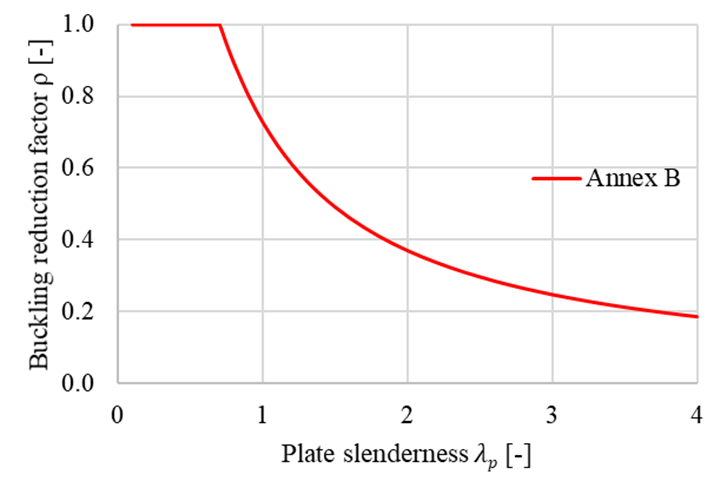
The reduction buckling factor ρ is determined according to Annex B of EN 1993-1-5. The reduction factor depends on the plate slenderness. The used buckling curve shows the influence of reduction factor on the plate slenderness. The provided buckling factor applicable to non-uniform members is based on the buckling curves of a beam. The verification is based on the von Mises yield criterion and the reduced stress method. Buckling resistance is assessed as
\[ \frac{\alpha_{ult,k} \rho}{\gamma_{M2}} \ge 1 \]
Buckling reduction factor ρ according to EN 1993-1-5 Annex B
Although the process seems trivial, it is general, robust and easily automated. The advantage of the procedure is the advanced FEM analysis of the whole joint which can be applied to general geometry. Moreover, it is included in the valid Eurocode standards. The advanced numerical analysis gives a quick overview of the global behaviour of the structure and its critical parts and allows fast stiffening to prevent instabilities.
The limit slenderness, λp, is provided in Annex B of EN 1993-1-5 and sets all cases which must be assessed according to the previous procedure. The resistance is limited by buckling for plate slenderness higher than 0.7. With the decreasing slenderness, the resistance is governed by plastic strain. The limit critical buckling factor for plate slenderness equals to 0.7 and buckling resistance equals to the plastic resistance may be obtained as follows
\[ \alpha_{cr} = \frac{\alpha_{ult,k}}{\bar \lambda_p^2} = \frac{1}{0.7^2} = 2.04 \]
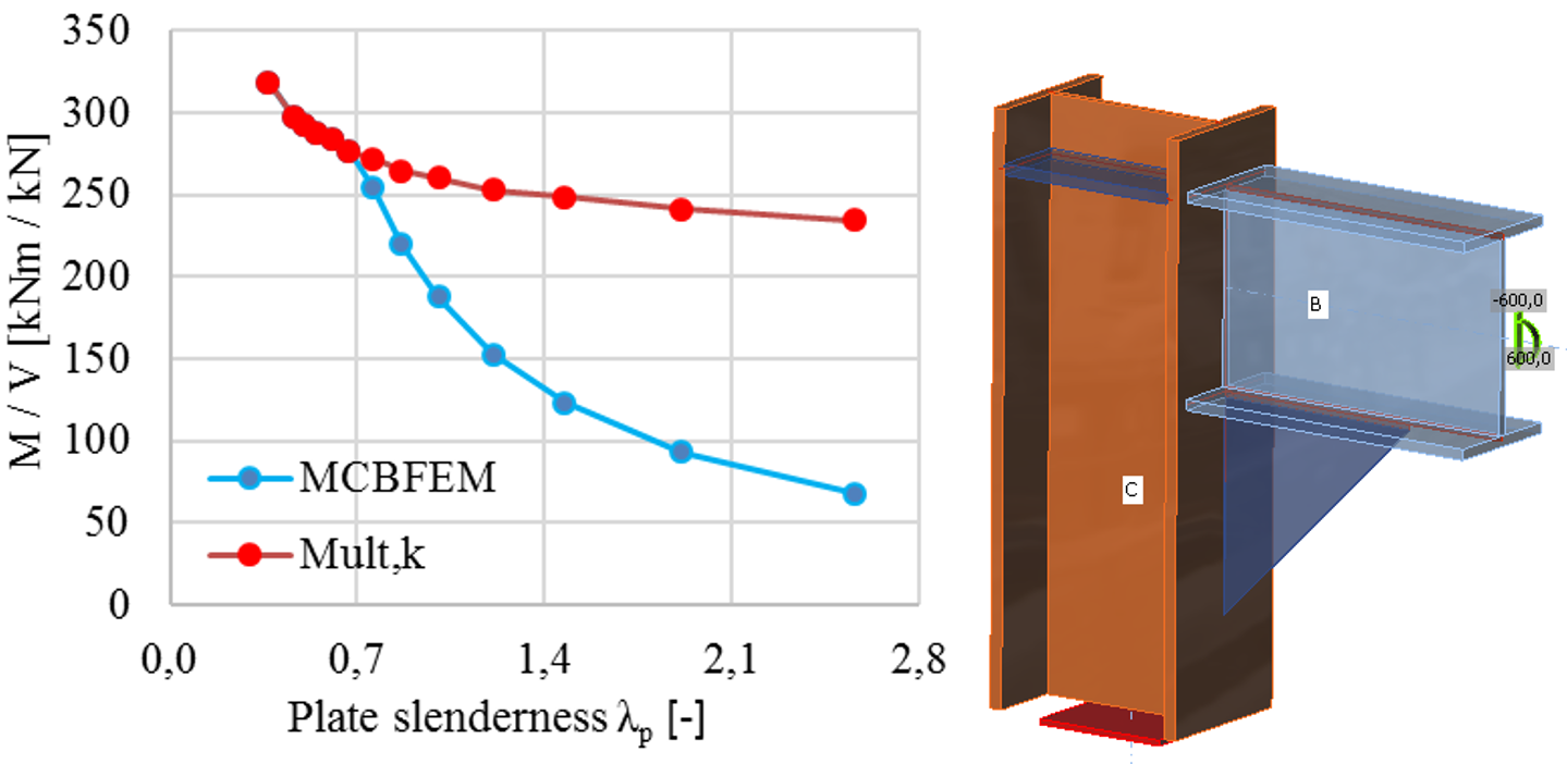
The influence of the plate slenderness on the plastic resistance, Mult,k, and buckling resistance, MCBFEM, is shown in the figure bellow. The diagram shows the results of a numerical study of a triangular stiffener in a portal frame joint.
The influence of plate slenderness on the resistance of portal frame joint with slender stiffener

