
Torsion moment induced by eccentric shear force
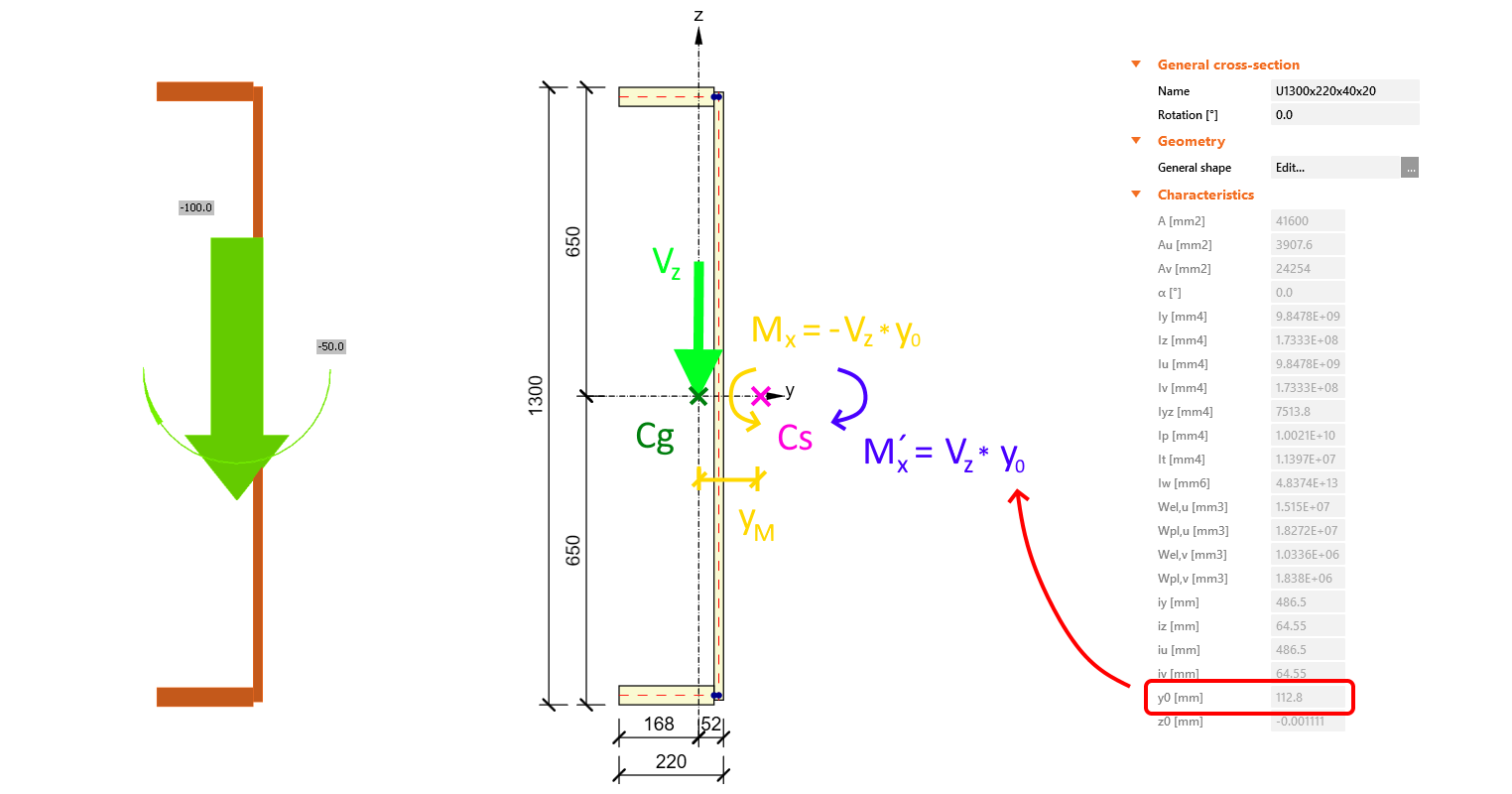
When a member with an asymmetric cross-section is loaded by a shear force, it produces an extra torsion moment Mx as well. This is because the point of action of the shear force in IDEA StatiCa Connection is always in the cross-section’s center of gravity (Cg). If the position of the center of gravity doesn’t match the position of the shear center (Cs), the resulting lever arm causes additional torsion.
This can be completely resolved by using the Lateral-torsional restraint operation to stabilize the member.
If you don't wish to use this approach, your model may show differences in results between versions 20 and 21, while it is more noticeable with the improved CBFEM model in version 21.0 and newer. Read about the version 21 updates in the blog post Condensed superelements - invisible but essential.

There are cases where you might wish to neglect this effect. For example, when the cross-section is prevented from twisting (e.g. by side beams or floor deck). In that case, contra torsion moment M´x has to be calculated and added in the load effects for this member to balance the extra torsion moment Mx.
For example, this beam with U cross-section gets twisted and shows unrealistic stress and deformation trend, and the code-checks are affected. In reality, the beam is prevented from torsion along its whole length so there should not be such an effect.

To correct the model, a contra torsion moment M´x has to be calculated and added in the load effects for this member. In this example, for LE1 the moment M´x = Vz * y0 = 1502 * 0,113 = 170 kNm has to be added extra.
