Seismic analysis in IDEA StatiCa Connection
Introduction
When designing the structure to resist the seismic load case combination, the engineer must choose a concept:
- Low dissipative structural behavior
- q = 1 to 2 (section class 4 → q = 1)
- No special requirements for steel structures
- Ductility class low (DCL)
- Dissipative structural behavior
- q ≤ 4 – Ductility class medium (DCM), section class 1, 2
- q > 4 – Ductility class high (DCH), section class 1
For low dissipative structural behavior, no special requirements are necessary, and usual connection checks are required. However, for high seismic loads, designing a structure resisting remaining in an elastic state is unfeasible, and dissipative structural behavior is necessary. The Member Capacity Design analysis in IDEA StatiCa Connection is meant for such behavior.
Possible structural types of seismic resisting systems allowed in EN 1998-1 are:
- Moment resisting frames (MRF)
- plastic hinges at the ends of beams or in the connections of the beams to columns
- plastic hinges may also be:
- at the column base
- at the top of the column in the upper floor
- Frames with concentric bracings (CBF):
- dissipative zones are located in the diagonals in tension
- Frames with eccentric bracings (EBF):
- dissipative zones in seismic links, mostly in beams
- Inverted pendulum structures
- Steel structures associated with concrete cores or concrete walls
- Dual frames made of moment-resisting frames combined with braced frames
- MRF contributes > 25 % to total strength and stiffness
- Moment-resisting frames combined with reinforced concrete infills
Determination of seismic load cases
Internal forces for seismic load combination may be determined by one of the following methods of structural seismic analysis:
- Lateral force method
- Linear modal response spectrum analysis
- Nonlinear static pushover analysis
- Nonlinear time-history dynamic analysis
Using linear modal response spectrum analysis causes internal forces to “lose signs” due to the method of square root of sum of squares (SRSS). The signs should be reobtained by the lateral force method – the joint in IDEA StatiCa must be in equilibrium. The seismic loads are in the accidental load combination, and the structure is analyzed. The joints are designed using standard Stress, strain analysis (EPS) in IDEA StatiCa Connection.
Furthermore, non-dissipative members must be able to safely, without significant deformations, transfer forces necessary to create the plastic hinges in dissipative members. This additional check is performed in Member Capacity Design analysis (MC).
Capacity design
The objective of capacity design is to confirm a building undergoes controlled ductile behavior in order to avoid collapse in a design-level earthquake. This involves designing the structure to allow ductile failure at key predictable locations within the structure and to prevent other failure types occurring near these locations or elsewhere in the structure.
In other words, in a structure that contains both brittle and ductile elements, capacity design is a method to provide the structure with an overall ductile characteristic.
Some members are considered as dissipative and others non-dissipative. Connections are usually non-dissipative but in some cases may be dissipative. Dissipative elements are expected to undergo significant plastic deformations during seismic load case, the seismic energy may be depleted at these deformations, and the seismic load is therefore significantly lower. On the other hand, dissipative elements must be able to withstand the cyclic strains without any cracks, and all non-dissipative elements must be able to transfer the load induced by dissipative elements. To ensure the formation of plastic hinge in the dissipative member, the probable yield strength is used instead of nominal yield strength, and sometimes, especially for beams in MRFs, also strain-hardening is taken into account. Thus, the strength of dissipative members is taken as:
\(f_{y,max} = \gamma_{sh} \cdot \gamma_{ov} \cdot f_y \) (EN)
\(F_{y,max}= C_{pr} \cdot R_y \cdot F_y \) (AISC)
where:
- γsh – strain-hardening factor, equal to 1.1 in EN 1998-1 and 1.2 in EN 1993-1-8; value 1.2 is recommended in ECCS manuals because it corresponds better to steel grades used for seismic applications; editable at dissipative element function
- γov – overstrength factor, recommended value is 1.25; editable in materials
- \(C_{pr} = \frac{F_y + F_u}{2 \cdot F_y}\) – strain-hardening factor – AISC 358-16 (2.4-2); may be turned on or off at dissipative element function
- Ry – ratio of probable to minimal yield strength – AISC 341-16 – Table A3.1; editable in materials
Ultimate (tensile) strength is also modified for elements selected as dissipative:
\(f_{u,max}= \gamma_ov \cdot f_u \) (EN)
\(F_{u,max} = R_t \cdot F_u \) (AISC)
where:
- γov – overstrength factor, recommended value is 1.25; editable in materials
- Ru – ratio of probable to minimal tensile strength – AISC 341-16 – Table A3.1; editable in materials
All the factors are modifiable allowing user a great degree of freedom. Moreover, multiple overstrength functions may be created with varying properties, but one plate may be selected only once. The strain-hardening factor is typically not used (equal to 1) for the analysis of braced frames. Note that safety (resistance/capacity) factors are not used for dissipative elements (members or plates with applied overstrength function).
Case study: Moment resisting frames
Typically, the beam is a dissipative member, in which plastic hinge is meant to form, and connection and the column are non-dissipative elements, which must remain without significant deformations. The beam is loaded by the load necessary to form plastic hinge in the beam with probable yield strength and by the corresponding shear force:
\[ M_{Ed} = f_{y,max} \cdot W_{pl} \]
\[V_{Ed} = \frac{2M_{Ed}}{L_h} + V_{gravity} \]
where:
- Wpl – plastic section modulus of the beam
- Lh – distance between two plastic hinges on the beam
- Vgravity – shear force due to gravity loading in the seismic combination
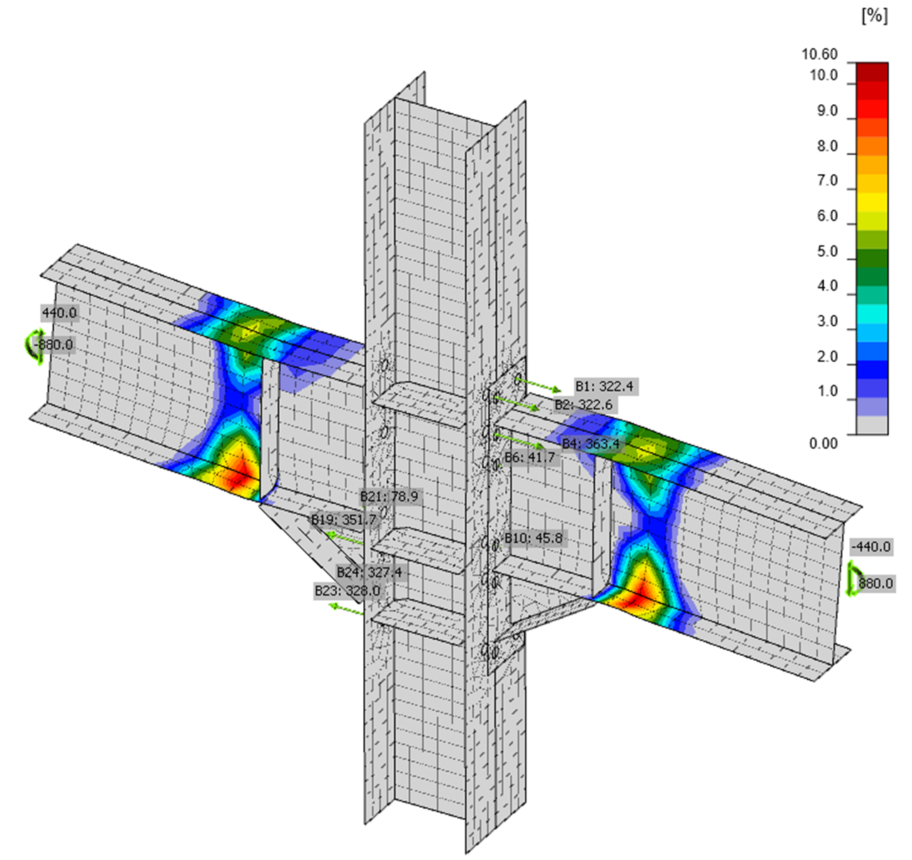
Note that if a double-sided beam-to-column joint is used, the forces must be from the same load case with correct directions, e.g.:
The shear forces are typically applied at the node for rigid joints. But the applied corresponding shear force is decreasing the bending moment at the plastic hinge. The moment at the plastic hinge is calculated as \(M_{Ed} = f_{y,max} \cdot W_{pl}\) and the bending moment My at the node is increased by the shear force Vz to \( M_y = f_{y,max} \cdot W_{pl} + V_z \cdot s_h \) where sh is the distance between the node and the location of the plastic hinge. AISC 358 specifies the value sh but for the distance between the column face and the plastic hinge.
Another option is to set \(M_y = f_{y,max} \cdot W_{pl} \) and set the position of shear force at the location of the intended plastic hinge (Model > Forces in > Position).
There may be other non-dissipative members connected to the joint. Such members should be loaded by gravity loads from the accidental seismic load combination.
Detailing
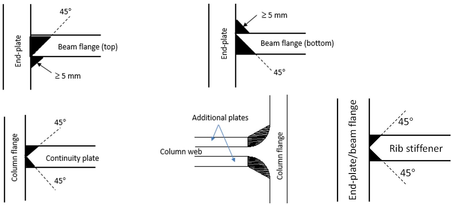
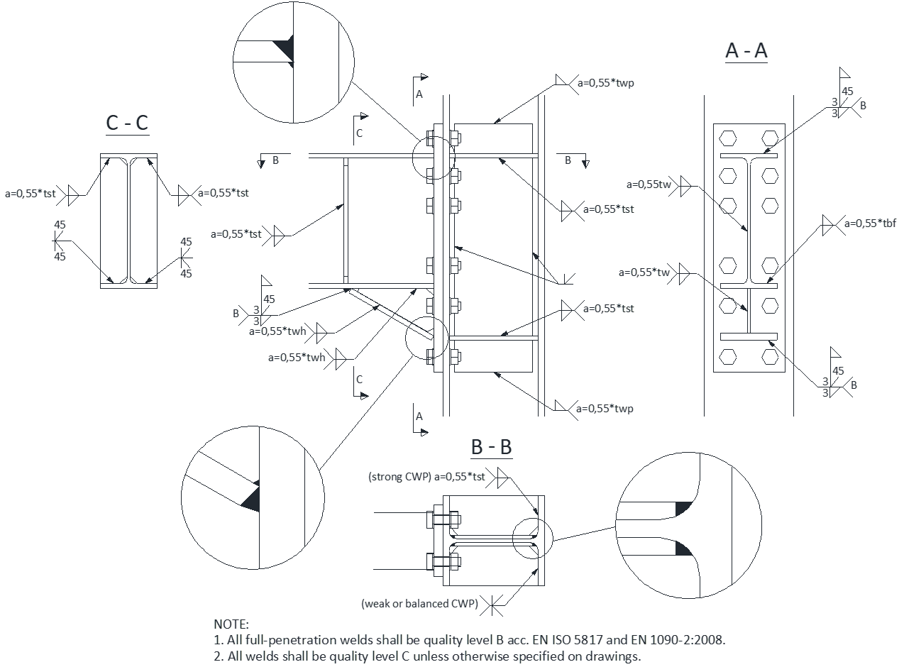
Detailing rules specified in relevant codes are not checked in IDEA StatiCa Connection and must be followed. Resistance against low-cyclic fatigue of many seismic-resistant joints was validated by experimental testing. Especially weld details are prone to fatigue cracking, and only a standard weld check is not enough for connections of dissipative members. Examples of weld details prescribed in project EQUALJOINTS are shown below.
Weld details of the groove full penetration welds of extended stiffened and unstiffened end-plate beam-to-column joints:
Weld details for haunched extended end-plate joints:
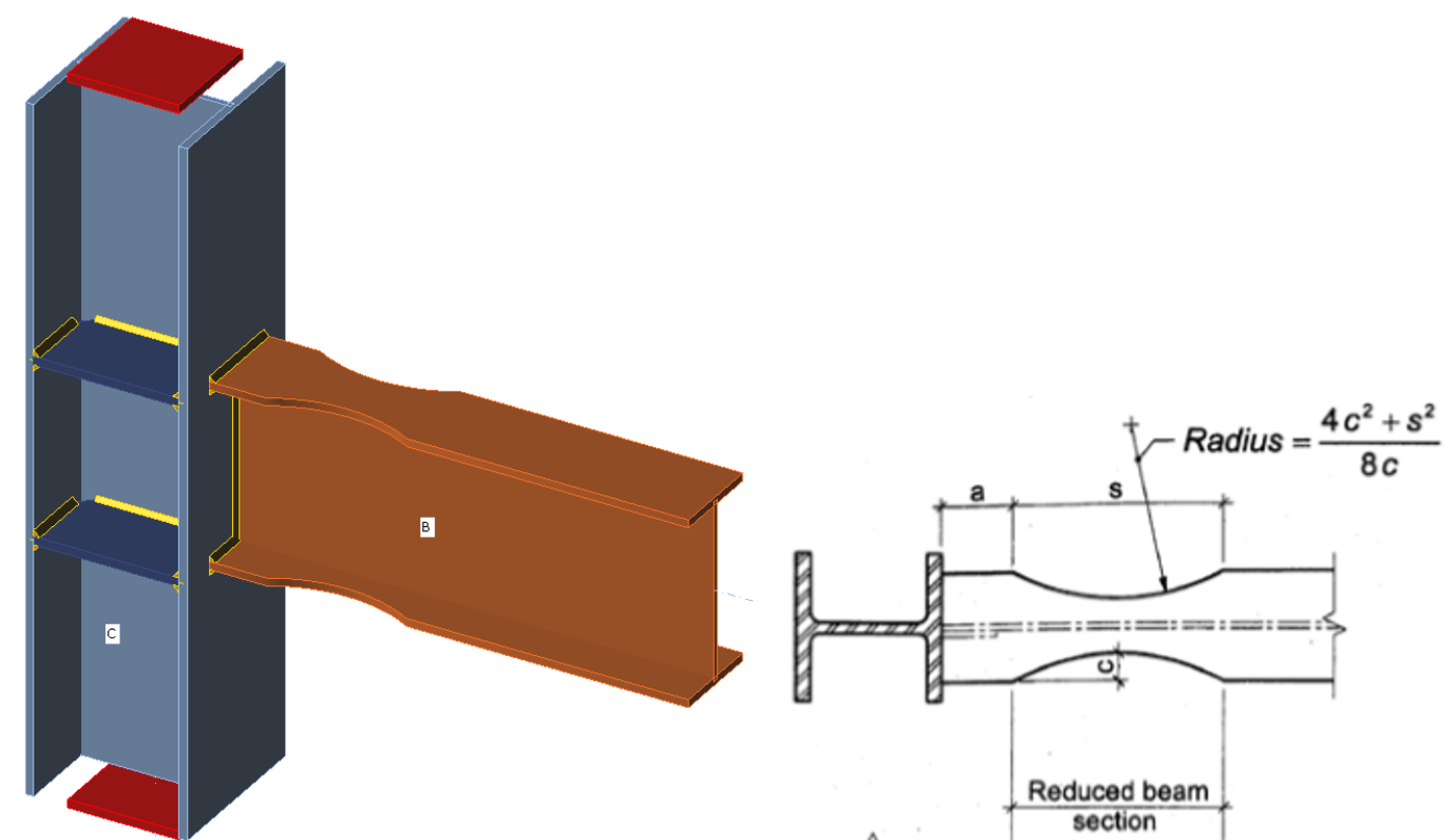
Dog bone
Beam flange width: bf
Beam depth: db
Maximum depth of the flange cut: c = 0.25 bf
Recommended depth of the flange cut: c = 0.20 bf
Distance between column face and beginning of reduced beam section: a = 0.6 bf
Length over which the flange is reduced: s = 0.75 db
The rotational capacity of the connection
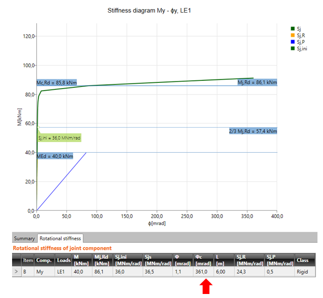
IDEA StatiCa Connection provides Moment-rotation diagrams for any connected member. Stiffness analysis gives (not only) the following results:
- Initial stiffness
- Limit capacity for 5% plastic strain
- Rotational capacity for 15% plastic strain
All of them are important for the proper seismic design of the connection. Rotational capacity (rotation ϕc) is used for the evaluation of the ductility of the connection. The given value can be compared with the values recommended in design codes.
Summary
The joint intended as a part of a seismic resisting system with dissipative structural behavior has to be checked against:
- standard load combinations (EPS analysis)
- accidental seismic load combination (EPS analysis)
- load necessary to form a plastic hinge in the dissipative member (MC analysis)
Code specified detailing rules must be followed.
References:
- EN 1998-1 Chapter 6: Specific rules for steel buildings
- EN 1993-1-8
- ACI 341-16 https://www.aisc.org/globalassets/aisc/publications/standards/seismic-provisions-for-structural-steel-buildings-ansi-aisc-341-16.pdf
- ACI 358-18 https://www.aisc.org/globalassets/aisc/publications/standards/a358-18w.pdf
- ACI 360-16 https://www.aisc.org/globalassets/aisc/publications/standards/a360-16-spec-and-commentary.pdf
- CSA S16-14


