
RFEM BIM link for concrete structure and beam design (EN)
1 How to activate the link
Install the latest version of IDEA StatiCa, get it in the Downloads.
Make sure you are using a supported version of RFEM – updates are published in the BIM section.
IDEA StatiCa automatically integrates the BIM link into your CAD/CAE software during its installation. You can check the status and activate more BIM links for later installed software in the BIM link installer.
Open IDEA StatiCa and navigate to the panel BIM and open the BIM link installer. A notification "Run as administrator" may appear, please confirm with the Yes button.
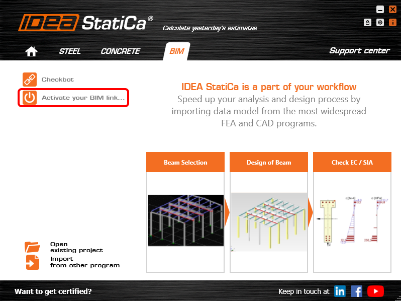
Select the software to integrate the IDEA StatiCa BIM link, click the Install button and check the Installed status.

2 How to use the link
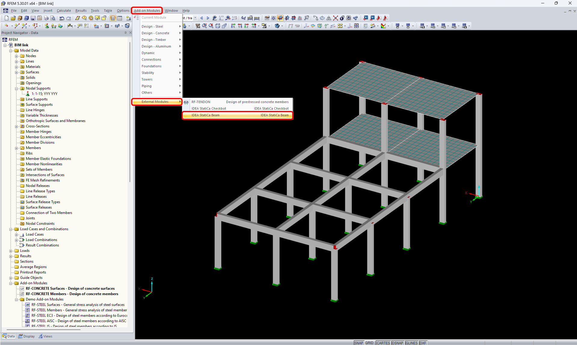
At first, download the source file. Then open it in RFEM and run the Calculation. In RFEM go to menu Add-on Modules then External Modules and run IDEA Beam.
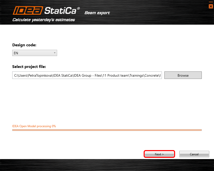
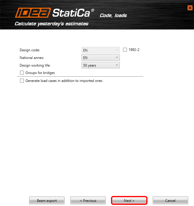
Select the code.

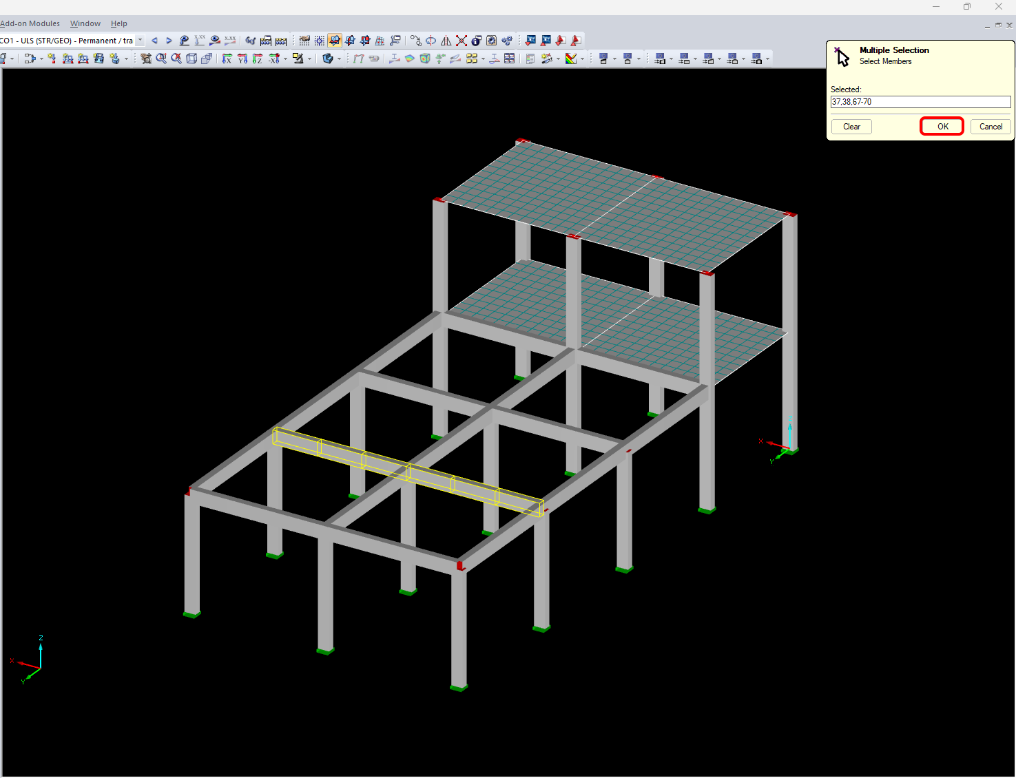
Selected members are 37,38,67,68,69,70. Confirm the selection by using the OK button.
You leave the default path and continue by Next. Notice: Keep the default path in order to further synchronization.
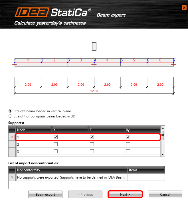
In the next step supports need to be defined. Restrain all translation X, Y and rotation around the global axis Y for node 1. Do the same for node 4 and 7.
Select Cast-in-situ concrete beam and option Reinforced concrete beam.

Leave the next table without any change and continue by Next.
Add all load cases coming from RFEM. The load cases will be inputted as user-defined internal forces.

Automatic data transfer has been started and IDEA StatiCa Beam and the beam with predefined setting is being launched.
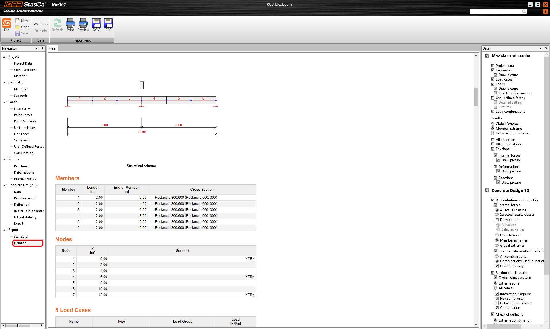
3 Project data
You can see the structural scheme of the designed beam. All predefined data can be changed in the Project data tab. Modify the Beam alignment and Supports position.

4 Load Cases
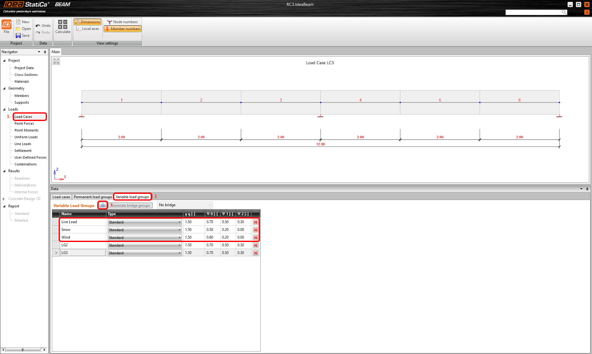
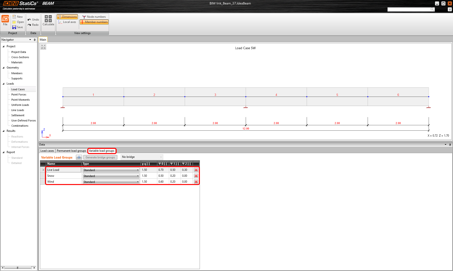
Go to the Load cases tab and select the Variable load groups to add the groups for live load, snow and wind and for the following renumbering of the partial factors.
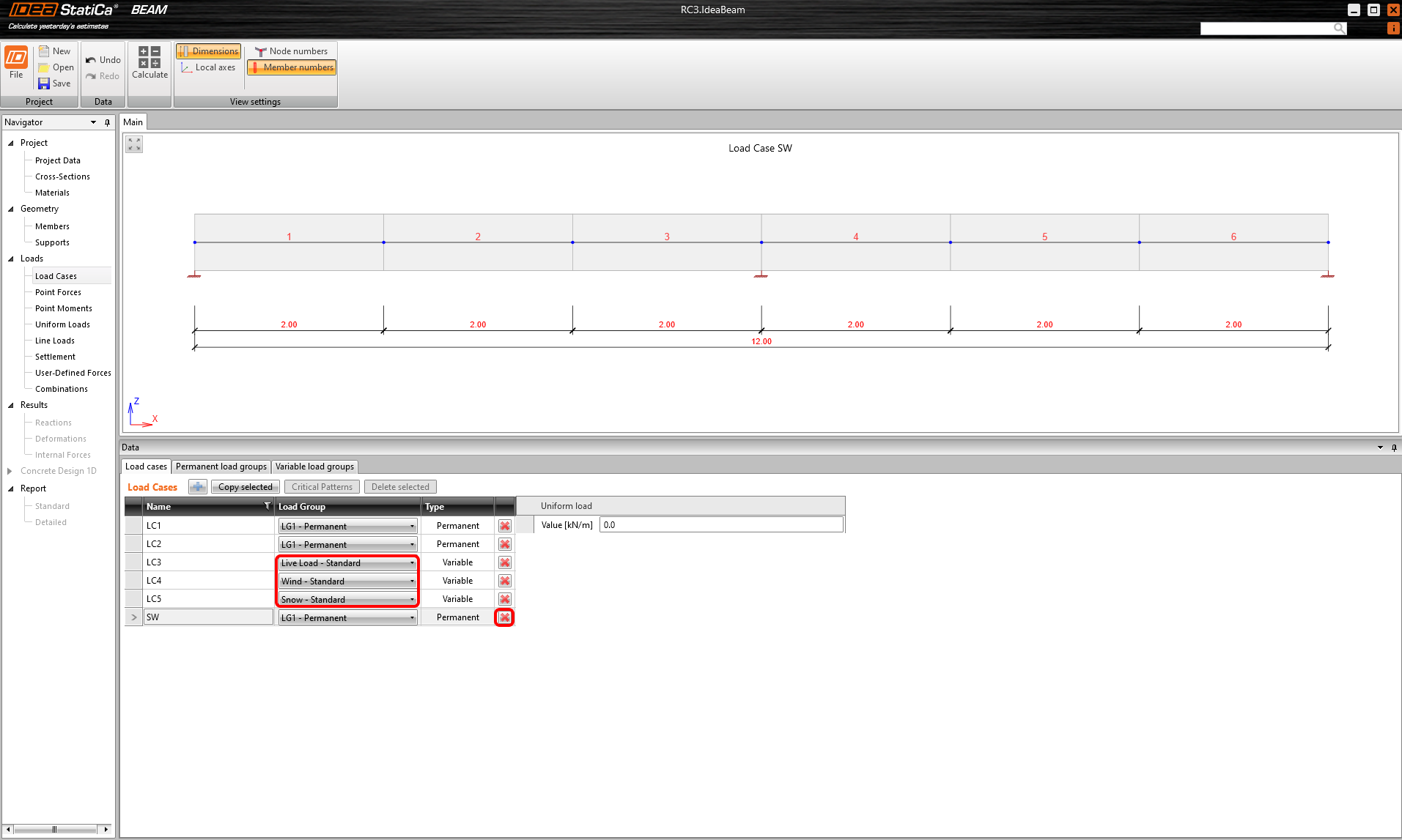
Then go back to the Load cases tab and assign the created load groups to the load cases. Also, delete the SW load case as self weight is already contained in LC1 from RFEM.
You can go back to the Variable load groups and delete groups that are not used to keep only the three you created.
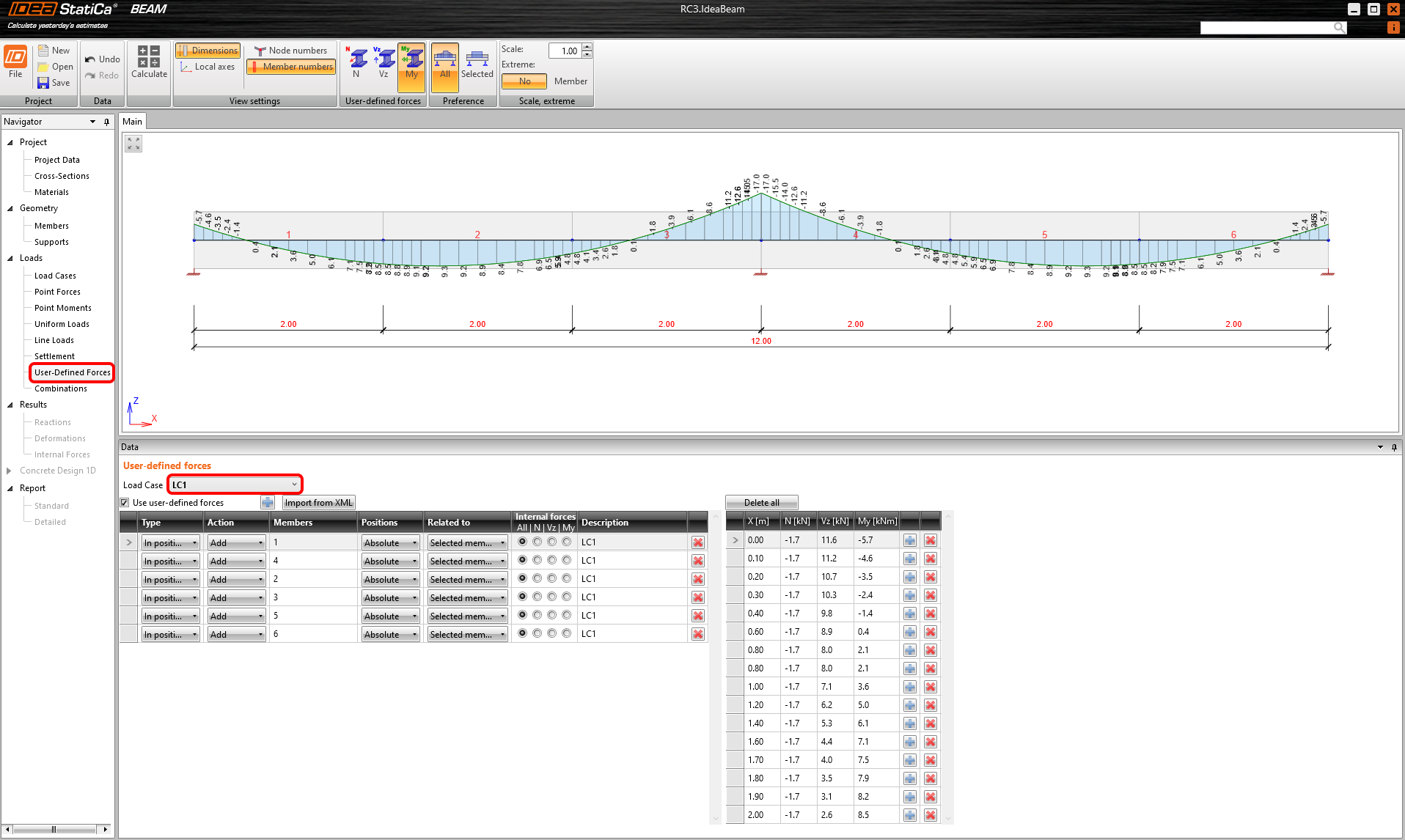
5 User-Defined Forces
How was mentioned the load cases from RFEM were imported as user-defined forces. You can control all internal forces of selected load cases. You can go one by one to compare the imported internal forces with the results in RFEM.
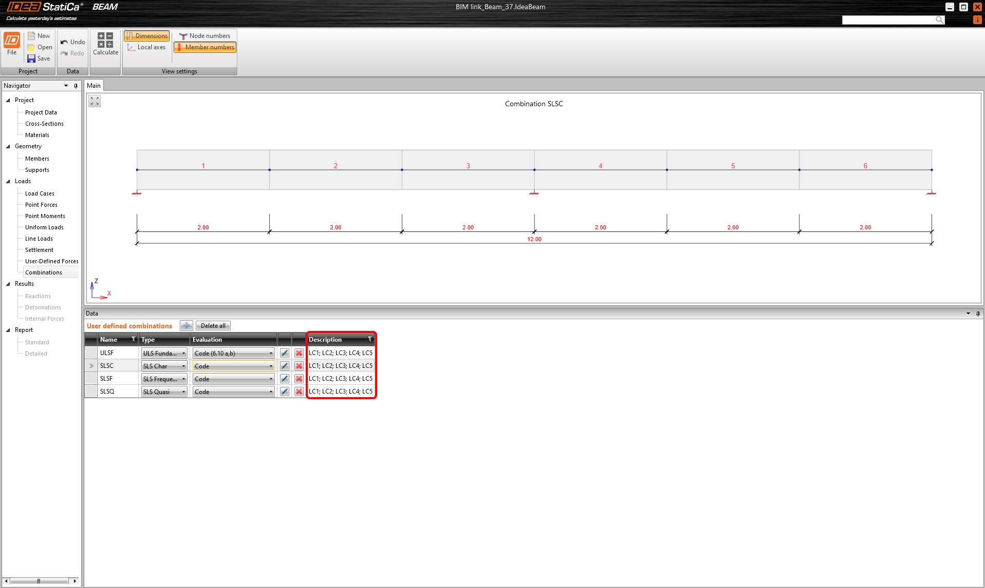
6 Combinations
Click Edit to define the combinations. Add all load cases to the ULS combination and continue with all SLS combinations as well.

The description table should be full of the load cases now.
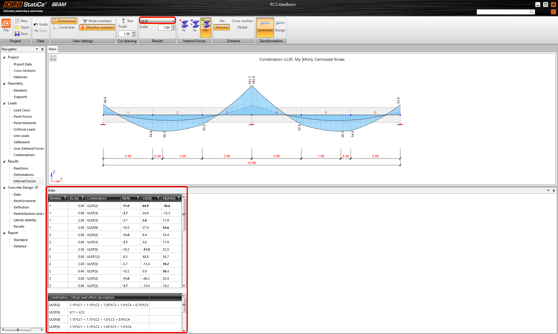
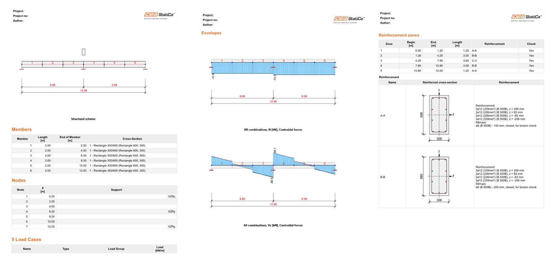
7 Internal Forces
You can check calculated internal forces of all combinations. The prescriptions of envelopes can be seen at the bottom of the window.
8 Concrete Design
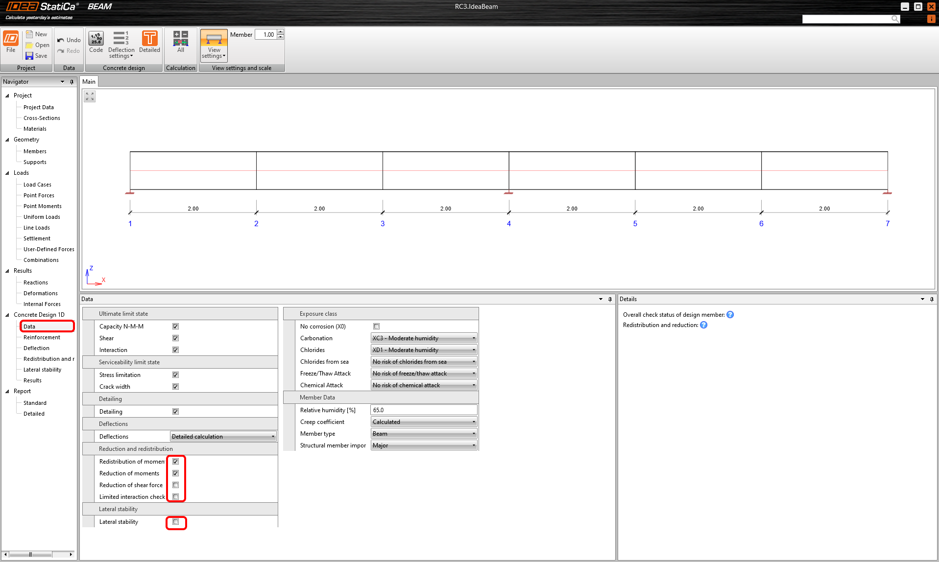
The settings of the checks can be defined in the Data tab. Switch off the checkbox for Lateral Stability and Reduction of shear force and switch on the checkboxes for the Reduction and redistribution of moments.
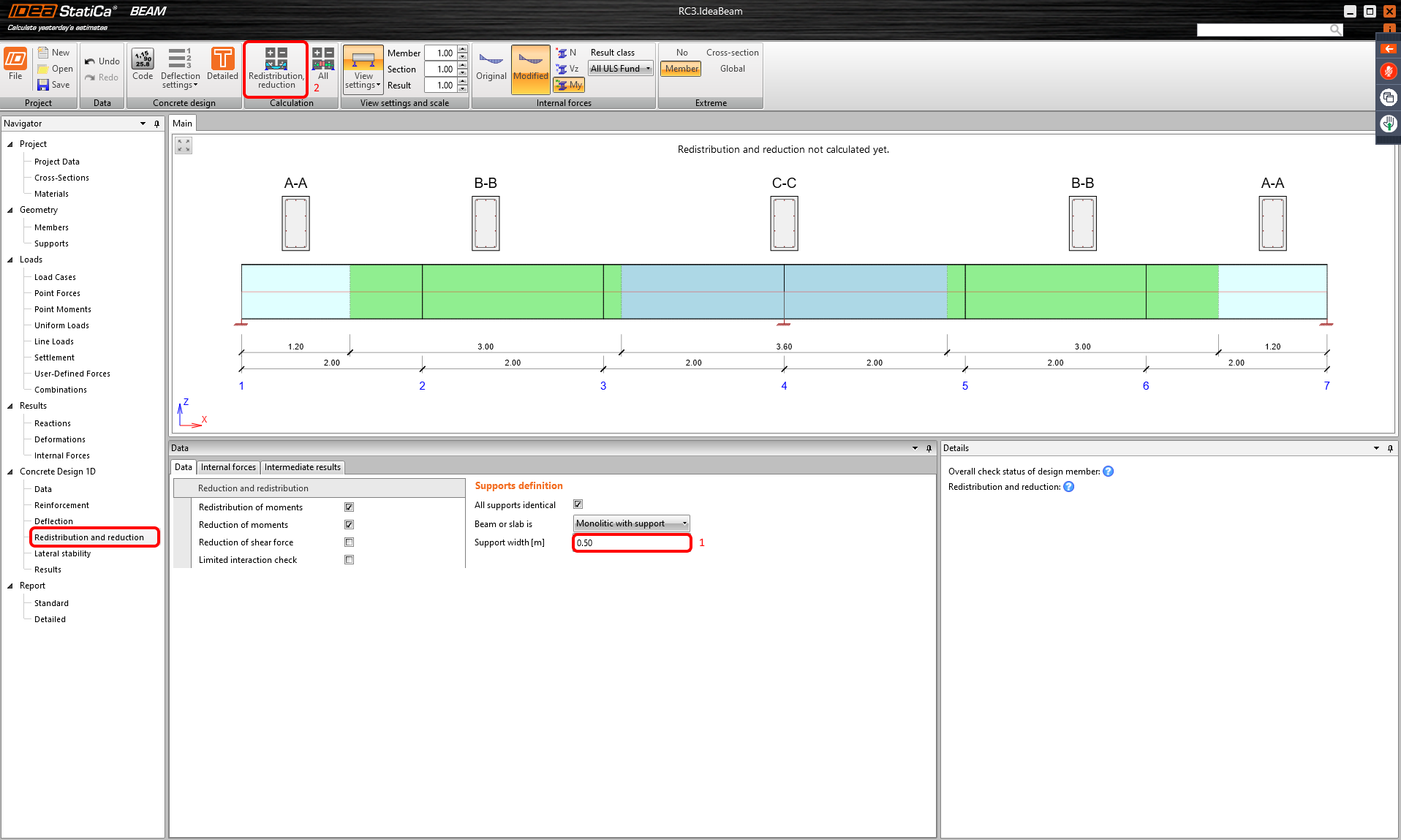
In the Reduction and redistribution tab modify the support width according to the width of columns of the structure. And continue with the calculation button.
9 Reinforcement
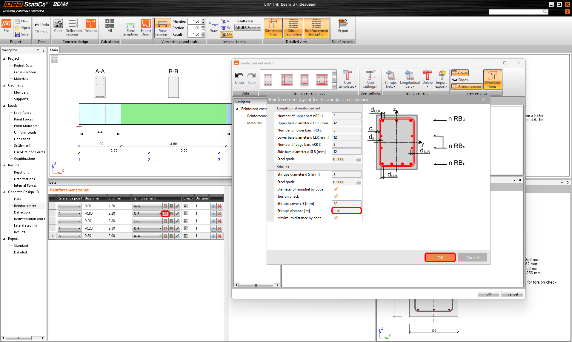
Go to the reinforcement. The option with three zones was automatically created by default according to the geometry. By using Zone templates you can modify the number of zones but for now, keep it as it is. Start with creating new reinforcement for the A-A section. Create the reinforcement by template, modify the input table and confirm by Ok. Continue with the same for section C-C.

Finally, repeat the steps for sections B-B. The program stores the setting of the previous inputs. Let’s change only the distance between stirrups to 0.20 m.
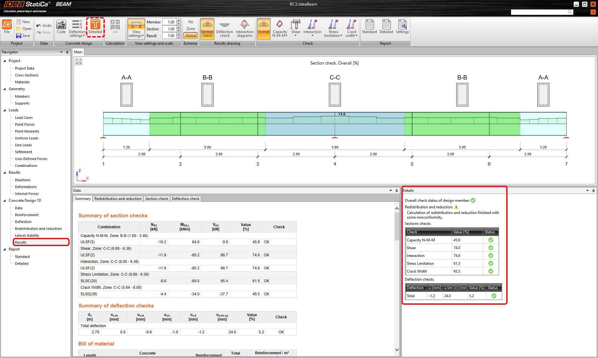
Push the Detailed check for better visualization and understanding of the behavior of the cross-sections in all CS. Or move to tab Results.
10 Results
See the summary of the checks.
11 Detailed Report
At last, go to the tab Report. IDEA StatiCa offers a fully customizable report to print out or save in an editable format.
You have designed, reinforced, and code-checked a prefabricated beam according to Eurocode.
12 Synchronize models

The code-check manager is a BIM tool to export and synchronize models from other programs. It is launched directly in the 3rd party applications via a command/icon.
Synchronize
IDEA StatiCa detects changes in geometry, profiles and load cases in the 3rd party application and updates respective IDEA StatiCa Beam projects.
Calculate
Synchronize and calculate the current item and provide a new set of results.
Calculate all
Synchronize and calculate all items and provide a new set of results.
We save the project in IDEA StatiCa and close the application Beam. All beams exported from the RFEM project to IDEA StatiCa are kept on the list inside RFEM.
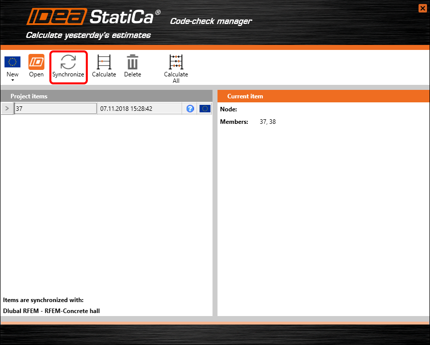
If we modify the project in RFEM (e.g. change the cross-section of any member or add other loads) we can simply update the project in IDEA StatiCa without setting it all again. We select the project item and click Synchronize and follow the export process. IDEA StatiCa opens and we can recalculate the updated project.