Dynamic grouping in Checkbot
Checkbot is optimized to handle models with hundreds of connections, providing tools for bulk operations. The grouping tools allow efficient management of connections by categorizing them based on typology and cross-section arrangement. This functionality simplifies navigation, selection, and enables to perform bulk design of multiple connections.
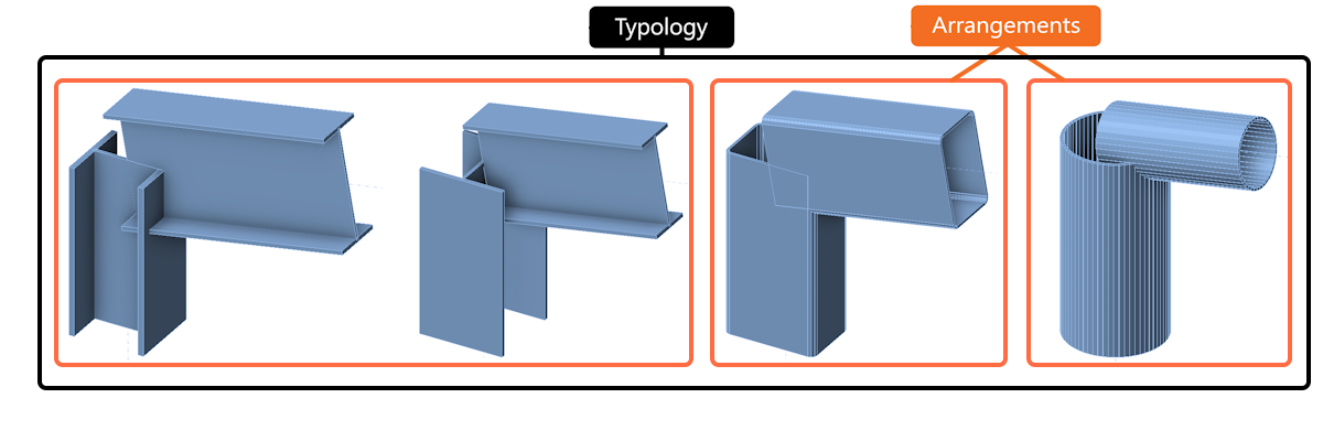
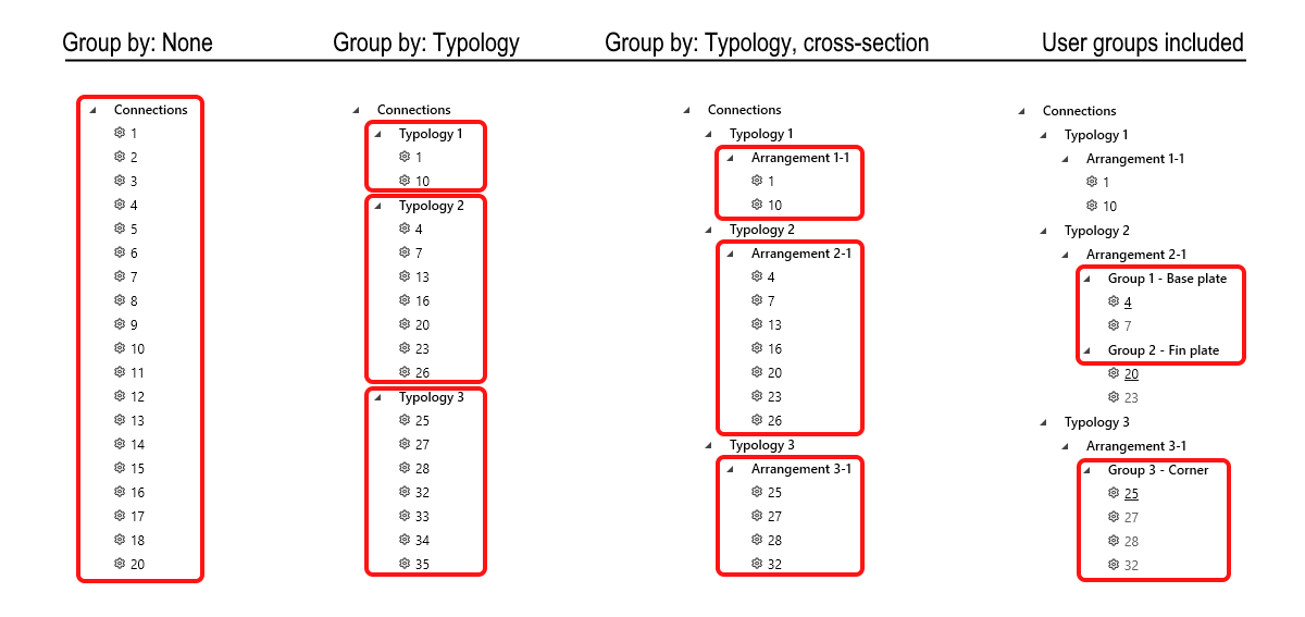
Dynamic Grouping automatically organizes connections in the project tree into two levels based on typology and cross-section:
- Typology – considers the number of members and their relative positions (e.g., beam-to-beam, beam-to-column).
- Typology, cross-section (Arrangement) – within the same typology, connections are further grouped by cross-section type. This is the lowest similarity that is required to enable searching for similar designs in the Connection Library.
The third level of grouping is defined as design groups, which are created and managed by users. These groups allow for further customization, enabling users to organize specific sets of connections based on their project needs. The only condition is that connections within the same design group must share the same typology and cross-section.
The creation of all levels of groups, including dynamic grouping and design groups, is handled by the project tree.
The connection tree can have four different ordering options based on the level of grouping.
Clear Connection tree
The tree and property grid offer users a clearer project overview and faster design management. These improvements enable quicker navigation and more efficient control of design properties, simplifying the process and ensuring critical details are easily accessible.
Sorting connections in the tree is based on the following:
- Node
- Name
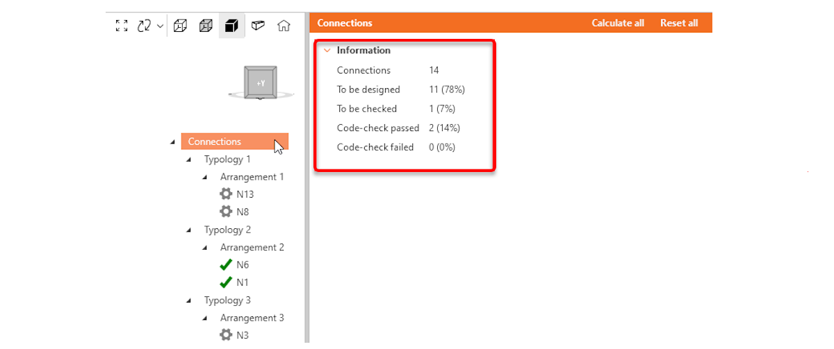
- Status (To be designed, To be checked, Code-check passed, Code-check failed)
Connection groups overview information:
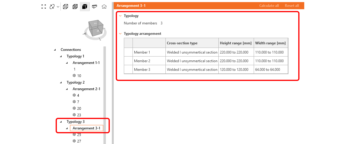
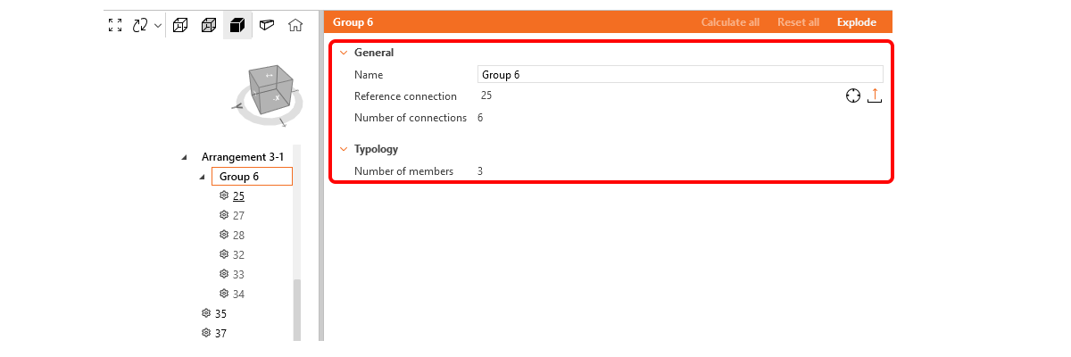
Users can now click the root group in the tree to instantly access an overview of information relevant to the selected group (Connections, Typology, Arrangement, Design group). This feature provides a centralized way to view key project details:
Connections
- Total number of connections
- To be designed
- To be checked (designed)
- Code-check passed
- Code-check failed
Typology and Arrangement
- Number of members
- Cross-section type of members
Design groups
- Name
- Reference connection
- Number of connections in a group
- Number of members in typology
Connection design with design groups
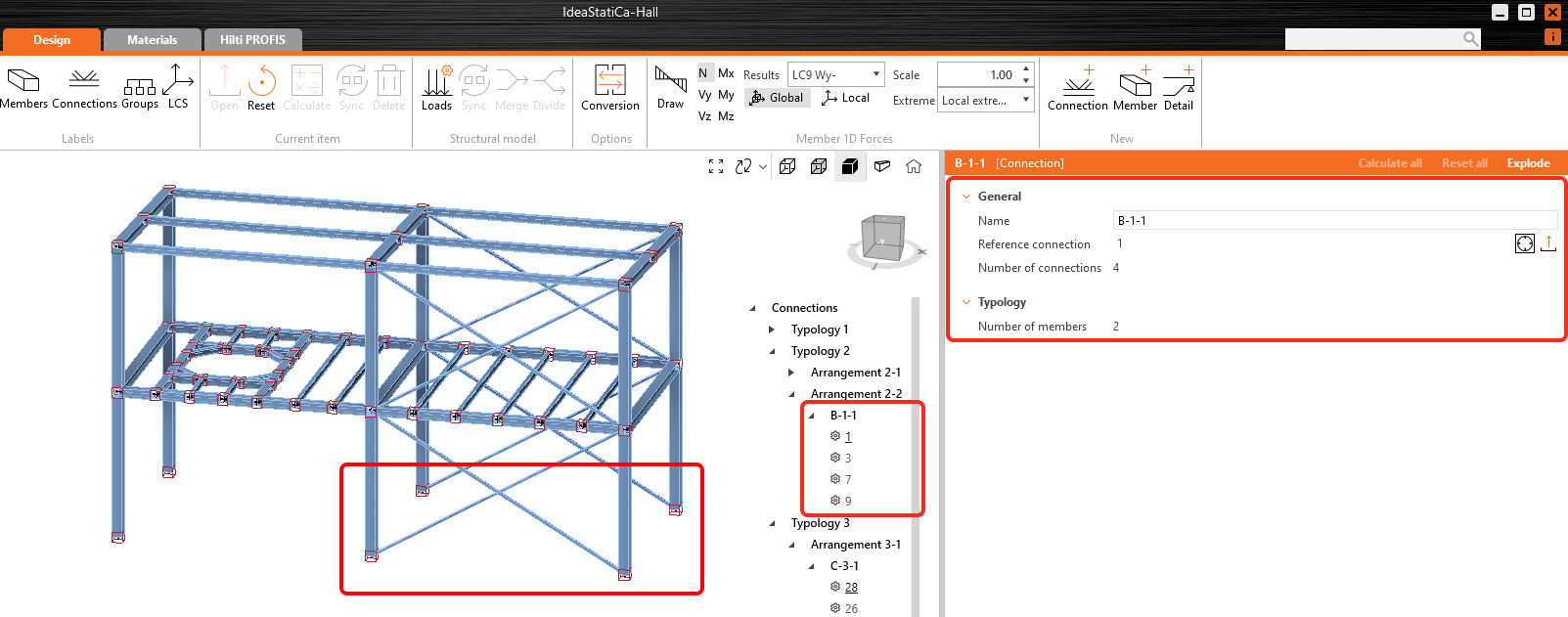
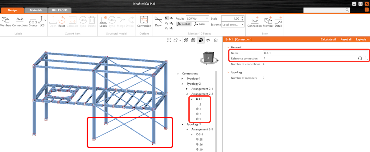
A design group allows a list of connections to be driven from one reference design, meaning the propagation (or templating) of a reference connection to all other connections in the group automatically. Groups are treated as specific objects with properties, and users can assign custom names to them. This saves users significant time when dealing with large sets of connections by automatically propagating design changes and operations to all child connections within the group.
User workflow
Standard group creation is as outlined below:
1. Group creation
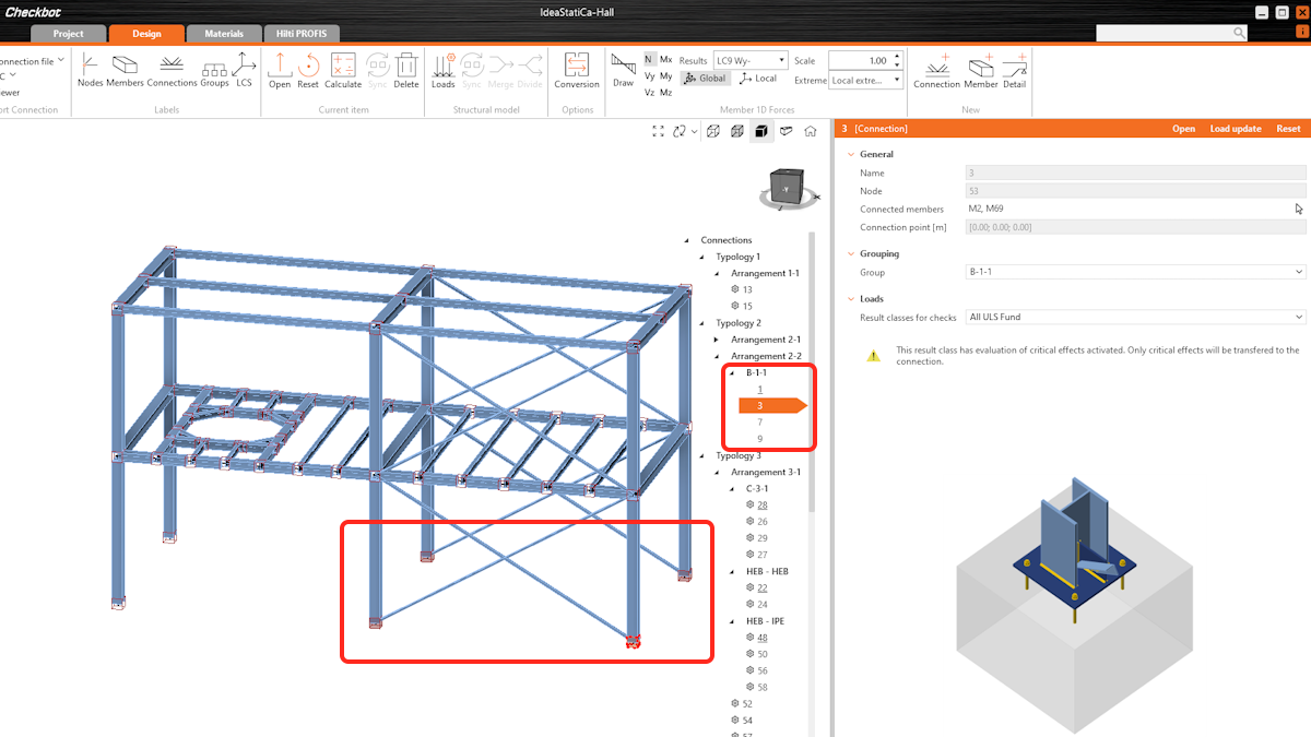
- Users select one or more connections to create a group. Connections must share a minimum similarity rule: the same typology and cross-section.
- The first selected connection automatically becomes the reference connection (the reference connection is underlined in the tree), which drives the design for the group. All other connections are considered child connections.
- The design group name can be defined as desired.
2. Design the reference connection
- The reference connection can either be designed manually or by applying a predefined template in the Connection app. To identify the reference connection, use the "sniper" symbol.
- All design operations and parameters from the reference connection are automatically propagated to the child connections, the section views included.
3. Automatic propagation to child connections
- Any changes made to the reference connection will automatically be applied to all child connections in the design group, ensuring uniformity.
4. Group Calculation
- The connections within the design group are calculated collectively.
Synchronization and validation
- When syncing with or updating the structural model, all child connections are validated against the reference connection.
- If any child connection no longer meets the reference connection’s parameters, it is flagged as invalid in the group.
Managing design groups
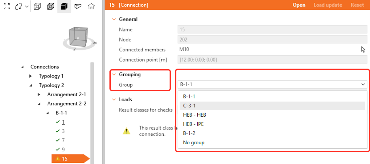
- Users can add, remove, or move child connections between design groups as long as the connections still meet the group’s validation rules (same typology and cross-section).
- A group can be exploded.
- Child connections can be removed from a group without exploding the group.
- Invalid child connections can be removed or corrected, and groups can be reconfigured as necessary.
- Reference connections cannot move between groups, the only way to remove or change the reference connection is to explode the group and re-create it. When a connection is marked as a reference, it cannot be deleted from the structural model.
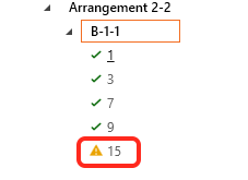
The key of the icons in the connection tree
Known limitations
- The model type of members in the reference connection is not propagated to Child connections.
- The position of forces of members in the reference connection is not propagated to Child connections.
Released in version 24.1

