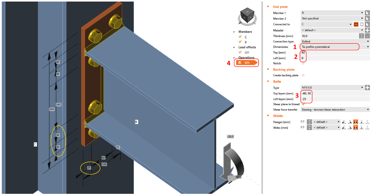
How to set position of bolts
For operations that produce bolts (Bolt grid or contact, End plate, Fin plate, etc.) the input of bolts position and definition of bolt coordinates differ. When you hover your mouse over the text, you can read a tooltip describing the type of input, e.g., for Rows and Positions for the general bolt grid.
Get familiar with the input of bolts for each operation by trying different values. You can always check the produced bolt grid dimensions in the 3D scene.
To display a 2D drawing with dimensions, go to the Editor of the operation and switch to the tab Drawing.
Input bolts position for End plate operation
Add the operation End plate and with the parameter Dimensions set the type end plate and thus bolt input.
Then input the symmetrical bolt positions by filling in the values of the Top layers and Left layers. For this operation, the values represent the distance from the outline of the cross-section toward the outside.
A multiple number of rows and columns of bolts can be specified using delimiters of two types:
Absolute delimiter ";" (a semi-colon) - distance measured from the outline of the cross-section (reference line)
Relative delimiter " " (space) - distance measured from the previous bolt row/column
E.g., the input of "40; 80; 120; 160; 200" is equal to "40 40 40 40 40" and also "4*40". You can also combine all delimiters, e.g., input "40; 80; 120 40 40".
You can check the bolt grid dimensions in the 3D scene.
Move a single bolt within a bolt grid
You can change position or move a single bolt or a row of bolts in a bolt grid in the Editor. Select the manufacturing operation containing the bolt grid, then Explode the bolt group and change the coordinates of any bolt separately.


