Fatigue analysis – Butt welds of I section
Description
Two beams of section IPE 200 from steel grade S355 are welded together by transverse full penetration butt welds. The beams at the position of the investigated detail are loaded by bending moment and normal stress:
| Normal stress N [kN] | Bending moment My [kNm] | |
| Minimum | 100 | 10 |
| Maximum | 300 | 30 |
Determination of nominal stress
Safety factor \(\gamma_{Mf}\) is selected from Table 3.1 (EN 1993-1-9). For this example, let's assume \(\gamma_{Mf} = 1.15\).
| Assessment method | Consequence of failure | |
| Low consequence | High consequence | |
| Damage tolerant | 1 | 1.15 |
| Safe life | 1.15 | 1.35 |
Analytical method
The nominal stress is determined by simple formula:
\[\sigma = \frac{N}{A} + \frac{M_y}{W_y} \]
For minimum normal stress, it is:
\[\sigma_{min} = \frac{100 \cdot 10^3}{2850} + \frac{10 \cdot 10^6}{194000} = 86.6 \, \textrm{MPa}\]
For maximum normal stress, it is:
\[\sigma_{max} = \frac{300 \cdot 10^3}{2850} + \frac{30 \cdot 10^6}{194000} = 259.9 \, \textrm{MPa}\]
The stress range is:
\[\sigma_{max} - \sigma_{min} = 259.9 - 86.6 = 173.3 \, \textrm{MPa} \]
There is no shear stress. Stress concentration factor kf is selected for appropriate detail. For full penetration butt welds across the whole cross-section loaded by normal force, the stress concentration factor is kf = 1.0.
\[\Delta \sigma_R = \gamma_{Mf} \cdot k_f \cdot (\sigma_{max} - \sigma_{min}) = 1.15 \cdot 1.0 \cdot 173.3 = 199.3\,\textrm{MPa} \]
CBFEM analysis
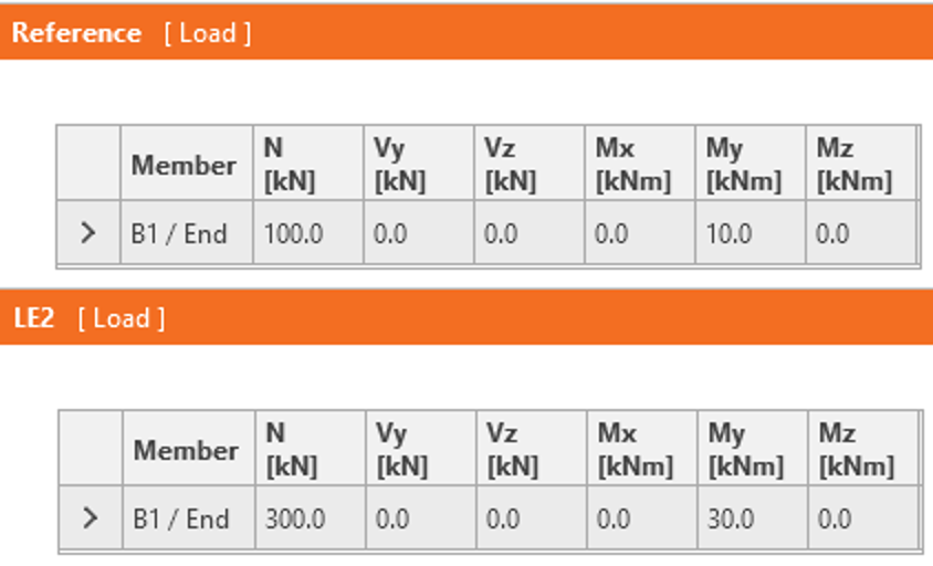
The loads are set as follows:
Reference load is the minimum load and LE2 is the maximal load.
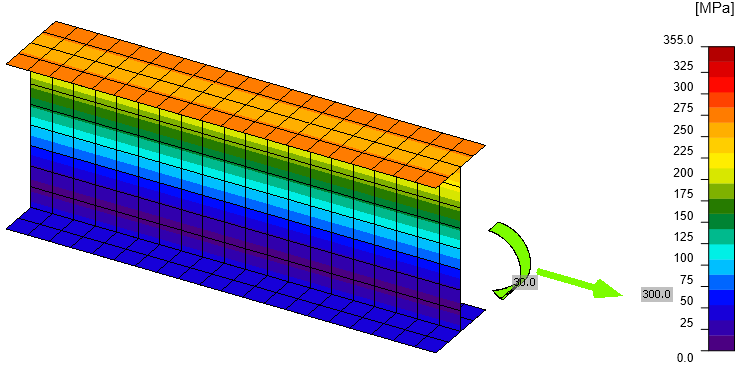
The von Mises stress at maximum load (LE2) shows that no part is yielding.
Planes are automatically generated near the butt welds and the stresses are shown in the check table:
The stress concentration factor kf is taken from finite element method and does not have to be applied again. The safety factor must be used.
\[\Delta \sigma_R = \gamma_{Mf} \cdot \sigma_{max} = 1.15 \cdot 178.1 = 204.8\,\textrm{MPa} \]
Comparison
IDEA StatiCa shows slightly higher normal stress (178.1 MPa) than the analytical approach (173.3 MPa). The only difference is caused by the assumed cross-section in IDEA StatiCa with slightly different cross-sectional parameters:
| Real | IDEA StatiCa | |
| A | 2850 mm2 | 2772 mm2 |
| Wy | 194 000 mm3 | 188 732 mm3 |
Using the cross-sectional properties of simplified cross-section, the same results as IDEA StatiCa are obtained: \(\sigma_{min} = 89.1\,\textrm{MPa}\), \(\sigma_{max} = 267.2\,\textrm{MPa}\), \(\sigma_{max} - \sigma_{min} = 178.1\,\textrm{MPa}\).
Fatigue analysis
An example of fatigue analysis using nominal stress is shown for a design according to EN 1993-1-9:2005.
The Detail category 90 is selected from Table 8.3.
For constant amplitude nominal stress ranges, the number of cycles for fatigue life is taken from Chapter 7.1:
\[N_R = \frac{\Delta \sigma_c^m \cdot 2\cdot 10^6}{\Delta \sigma_R^m}\]
Hand calculation:
\[N_R = \frac{90^3 \cdot 2\cdot 10^6}{199.3^3} = 184\,177\, \textrm{cycles}\]
IDEA Connection:
\[N_R = \frac{90^3 \cdot 2\cdot 10^6}{204.8^3} = 169\,734 \, \textrm{cycles}\]
The number of cycles that the joint can endure is slightly lower in IDEA Connection due to the simplification of the cross-section.
Benchmark case
Inputs
Members: B1, B2 - IPE200
Steel grade: S 355
Load effects:
- Reference: N = 100 kN, My = 10 kNm
- LE2: N = 300 kN, My = 30 kNm
Manufacturing operations: Cut by Mitre cut, Butt welds
Outputs
Maximum normal stress range: 178.1 MPa at top flange
Shear stress range: 0 MPa


