Equilibrium and supporting member
Ended and continuous member
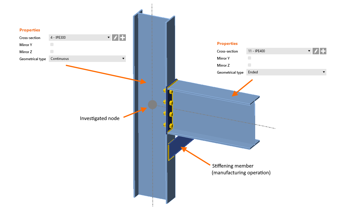
Each member of the connection model is either defined as Continuous or Ended in the Geometrical type field.
The continuous member is considered to continue further to opposite nodes on both sides, there is no "connected" end at the investigated node and both ends of the continuous member can be loaded.
The ended type is considered to end at the investigated node: there is one connected end and the member can be loaded on the opposite side only (the "free end" which in fact continues further in the global model).
Note: If you need to define a member that is cut on both ends and does not continue further to the structure, use the Stiffening member operation.
Bearing member
One member of the joint is always "bearing" (or supporting) and all the others are "connected". The bearing member is underlined in the list of members in the scene and red squares are depicted at the "continuous" ends of the member (as a symbol of support). The bearing member can be chosen by the designer if needed.
For other symbols of the boundary conditions see the article about the Model type.
Equilibrium of load
The internal forces in each node of the frame must be in equilibrium. Especially in the case of a continuous member, we need to carefully input internal forces to all members so the equilibrium is kept in the node.
In the definition of Loads, two options can be chosen regarding the equilibrium.
- Simplified – for this mode, the bearing member is supported (continuous member on both ends) and the load is not defined on the bearing member
- Advanced (default) – the bearing member is supported on one end only, the loads are applied to all members and the equilibrium of forces has to be found
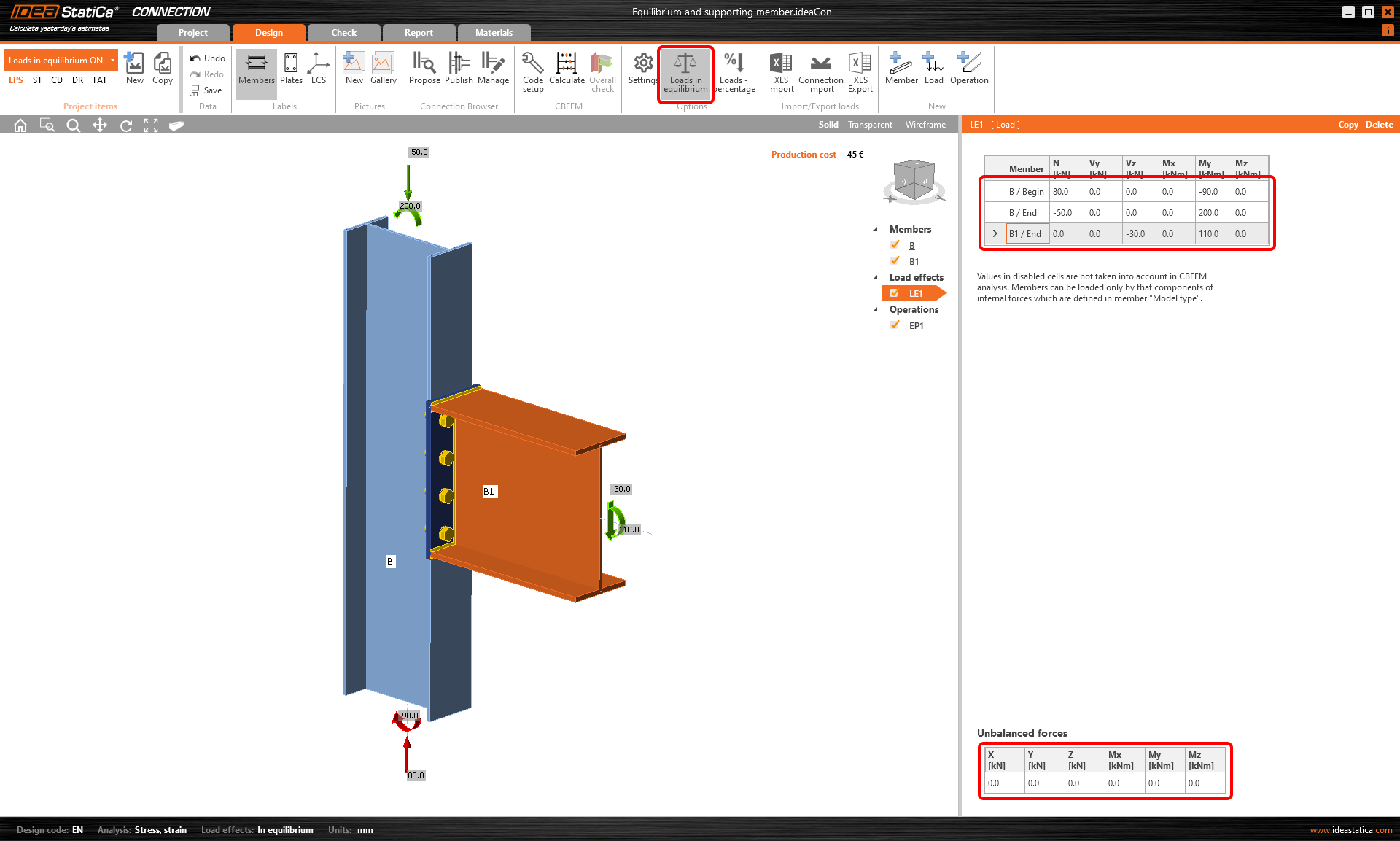
The mode can be switched in the top ribbon by Loads in equilibrium button.
By default, the Loads in equilibrium option is switched on (since version 22.0 of IDEA StatiCa, see the section of Release notes 22.0). In this case, the table of unbalanced forces is displayed and the user is responsible for keeping the loads in equilibrium). Any unbalanced forces are applied to the supports.
It is important to realize that disrupting the equilibrium condition may lead to false and unsafe results. Also, using the simplified load method (with Loads in equilibrium off) does not take the full picture of the stress of the connection into account and may lead to false results.
Example
Let's demonstrate the difference in the following example:
The attached connection of a loaded beam (B1) to a continuous column (C) has the Loads in equilibrium option deactivated.
After we Calculate the project, the results are provided in the 3D scene. All performed checks are satisfactory.
Now, we will copy the project and activate Loads in equilibrium. The table with Unbalanced forces appears. We can input internal forces on both ends of column C and check the equilibrium of input nodal forces.
Again, we Calculate the CON2 project, and we see that the welds did not pass the code check. The reason is the correct load action that added to stresses in the column flange that we considered this time.
Simplified method
The equilibrium requirement is correct. Nevertheless, it is not necessary to design some simple joints. If only a part of the connection is checked (simple ones, e.g. a beam to column connection) and we are not interested in the interaction with the load on the supported member, there is an option to switch off the equilibrium condition. Please do it after careful consideration only.
Webinar recording
See the recordings of our webinars where the Bearing member and Equilibrium are discussed live.
Attached Downloads
- Equilibrium and supporting member.ideaCon (IDEACON, 61 kB)


