Code-check of welds according to Australian standards
Fillet welds are checked according to AS 4100 - Chapter 9.6. The strength of CJP groove welds is assumed the same as the base metal and is not checked.
It is possible to set butt welds or fillet welds and along the full edge length, partial welds, or intermittent welds. Butt welds are assumed to have the same strength as the welded member and are not checked. In the case of fillet welds, the weld element is inserted between interpolation links connecting plates to each other. The weld element has a specified elasto-plastic material diagram to redistribute the stress along the weld length so that the long welds, multi-orientation welds or welding to unstiffened flange have similar resistance as according to hand calculation. The most stressed weld element is decisive in the weld check.
A fillet weld subject to a design force per unit length of weld, vw*, is designed according to Cl. 9.6.3.10 and shall satisfy:
\[ v_w^* \le ϕ v_w \]
where:
- ϕ = 0.8 – capacity factor (Chapter 3.4) editable in Code setup
- vw = 0.6 fuw tt – nominal capacity of a fillet weld per unit length
- fuw – nominal tensile strength of weld metal (Table 9.6.3.10 (A))
- tt – design throat thickness
The reduction factor, kr is assumed equal to 1 (weld shorter than 1.7 m).
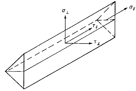
The weld diagrams show stress according to the following formula:
\[ \sigma = \sqrt{ \sigma_{\perp}^2 + \tau_{\perp}^2 + \tau_{\parallel}^2 } \]

