CBFEM validation: Block shear behavior
Block shear resistance is calculated a bit differently in each code. In this example, the block shear resistance by CBFEM is compared to the experimental program described in a detailed report created at the University of Alberta in Canada.
Material and geometry
Plate material: 350W (\(f_y = 350\,\textrm{MPa},\,f_u = 450\,\textrm{MPa}\))
Steel resistance factor: \(\phi=0.9\)
The real material properties are surprisingly lower than the nominal values (Table is taken from the report). In CBFEM, the nominal values with the resistance factor are used.
Plate thickness: 6.4 mm
Bolts: 1/2 in diameter, grade A325, bolt hole diameter = bolt diameter
The test set-up consists of a reinforced connection (upper part) and a test connection (lower part). In CBFEM, only the test connection is modeled. The figure below is taken from the report.
There were two variants of geometry:
- Bolts close to each other (spacing 51 mm; specimens T1A, T1B and T1C)
- Bolts with larger spacing, 152 mm (specimens T2B and T2C)
Results
The deformation of CBFEM is read from similar locations as in the experiment in a developer mode, where displacements may be visualized. The values are read from the scale so the deformations are not exactly precise.
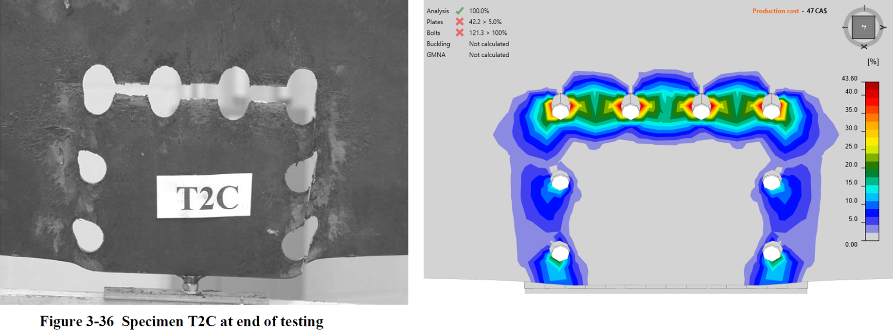
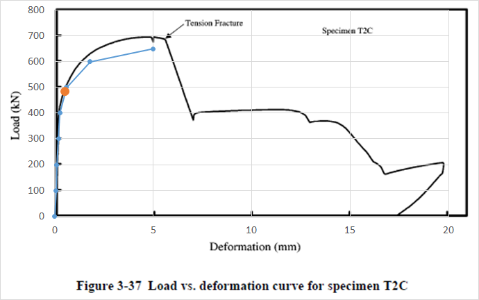
The load-deformation curves correspond quite closely to experimental graphs taken from the report. The differences are in the used nominal values and resistance factor in CBFEM. The model also uses only a bilinear material diagram with insignificant strain-hardening. Furthermore, the deformed shape by CBFEM corresponds well to the experiment, and plastic strain is concentrated around the upper part between bolts hinting that the tensile rupture will occur before shear rupture at sides.
It is important to note that the 5% limit plastic strain (orange dot in the graphs below) is reached at very small deformation and long before any fracture. The tensile fracture occurs at 45% and 42% plastic strain for geometry T1 and T2B/C, respectively. The shear planes are even more ductile but the load resistance is already decreased significantly.
Conclusion
In CBFEM, block shear resistance of a group of bolts is determined by finite element analysis and is checked by 5% limit plastic strain. This comparison to experimental results from the research report shows that the load-deformation diagram closely fits even though a relatively coarse mesh and simplified material model are used in CBFEM. Another important finding is that the 5% limit plastic strain is reached at a very small deformation long before any fracture.
CBFEM is intended to determine the design resistance and not the real behavior of connections perfectly. Although 5% limit plastic strain is very safe in these two cases of block shear resistance, users should not increase this limit.
References:
Huns, Bino Baljit Singh, Grondin, Gilbert Y., Driver, Robert G. Block shear behaviour of bolted gusset plates, Structural engineering report SER 248 | SER-ID SER248, University of Alberta, 2002. Available at: https://era.library.ualberta.ca/items/cf9bf338-36ca-4557-9bb2-ee198954bd00


