Tekla Structural Designer BIM link for connection design (EN)
About the BIM Link
New for Service Pack 2 of Tekla Structural Designer 2022 (July 2022) comes an integration (written by Tekla with close cooperation from ourselves) with IDEA StatiCa Checkbot. This update is available for all new and existing customers with valid support contracts. For more information refer to the release notes for this release and in particular this section.
How to use the link
We have created a model for you to use - you can find it here.
Open the model using Tekla Structural Designer 2022.2 or later, calculate all and then save it.
There are two steps in creating nodes with connections.
The first step is to create connections at nodes within Tekla Structural Designer:
Navigate to the Connections window (1) and then right mouse click within it and select Update Connections (2).
This populates the model with viable connections and they will be visible in the Connections window (3) and as connection boxes on each applicable node (4).
The second step, now that we have connections in the model is to export them to IDEA Connection via Checkbot.
There are three ways to do this:
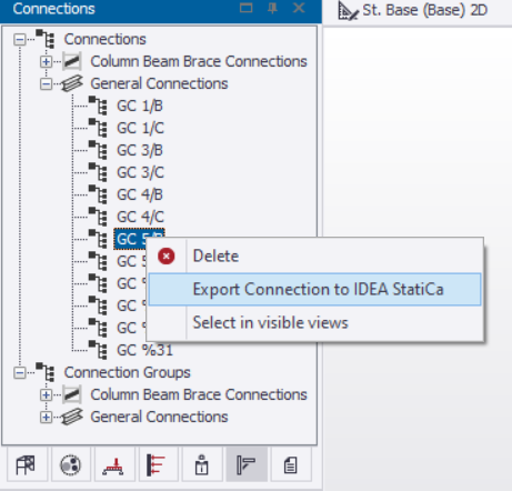
1 - Right mouse click on an item in the Connection window and select Export Connection to IDEA StatiCa;
2 - Right mouse click on the connection box and select Export Connection to IDEA StatiCa;
3 - Navigate to the BIM Integration tab and select IDEA StatiCa.
The last option opens up the Tekla Structural Designer interface to Checkbot.
Geometry
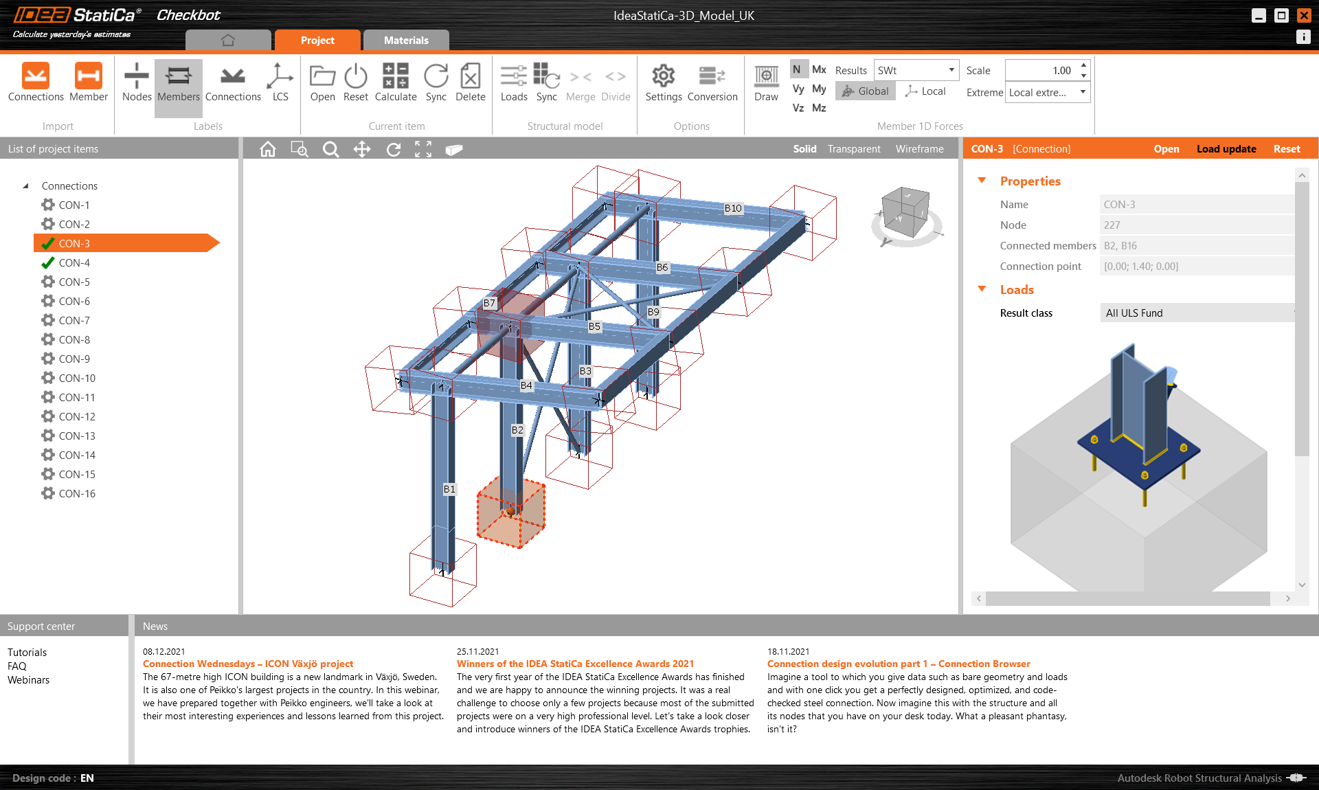
In the list of project items under Connections and with a connection highlighted in Checkbot you can either right-mouse click and select Open or click the ribbon command Open to start designing, code-checking, and reporting.
The settings of members are taken from the original FEA/BIM application. You can, however, change the section size of any member on the main Checkbot screen, but this will break the link with FEA/BIM application in this session unless it's synchronized again.
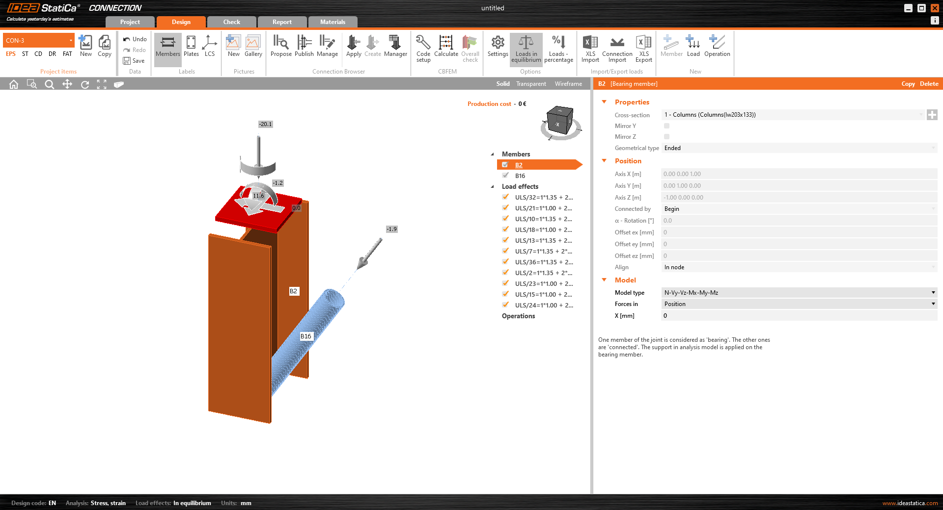
The imported connection is opened in the IDEA StatiCa Connection application.
You may see none or different Load effects from your preferred FEA/BIM* solution depending on how the load case combinations have been defined. By default, IDEA StatiCa will choose the most critical for code-checking purposes. (* Some BIM solutions are not able to store the load case combination results)
For more information on Load effects see here.
Design - Column baseplate
This is the second connection to be designed.
Select Con-3 at the bottom of the first internal column and press Open.
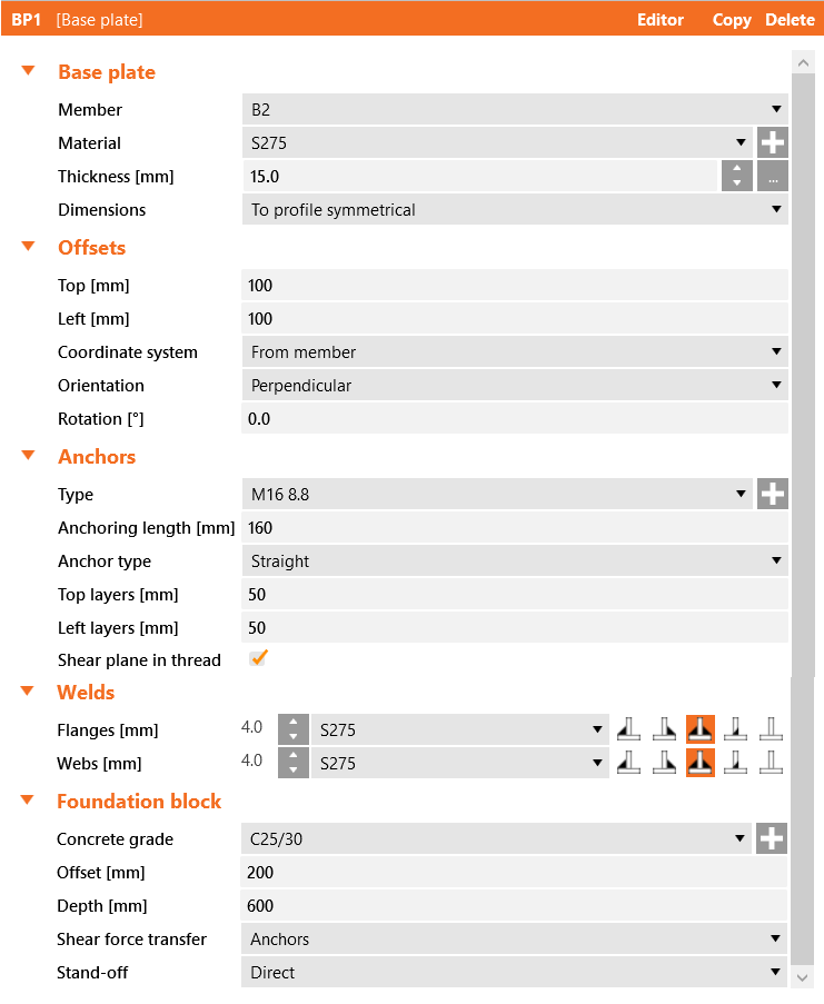
Apply a baseplate operation using the parameters below:
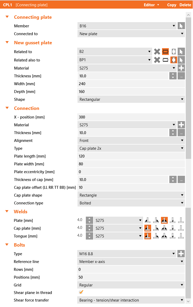
To connect the brace to the baseplate we shall use the Connecting plate operation, connecting this to both the column and the baseplate:
The gusset for the connecting plate should have a rounding on it of 40mm and the tongues 20mm.
That completes the connection for the column baseplate.
Calculate, Save and Exit this connection back to Checkbot.
You will see that there is another green tick next to the connection. This means that the connection is valid and has passed its code checks.
Synchronize connections
Sometimes, there are changes to your FEA/BIM model, such as different member section size or loads. These can be synchronized between Checkbot and the FEA/BIM model.
There are two possible alternatives:
- Synchronize the Current item (if one or more joints are selected)
- Synchronize the whole imported Structural model
To test this feature, you can change a member section size or shape in your FEA/BIM application or amend a load case or combination etc: change columns to a smaller section. Remember to re-analyze the FEA model.
In Checkbot select the designed connections (there may be more than one) and from the Current item panel select Sync.
The Checkbot project will be updated, connection design is preserved, but the results will be invalidated. You can see that the column is now updated - matching the change in the FEA model.
Simply code-check the highlighted connections again by selecting Calculate from the Current item panel. Please remember that bigger changes in the model might require additional validation steps with the affected connections (as above).
If the connections do not give the desired results, then you can open them again to optimize the design (i.e. strengthen if they fail the code-check or lighten if the utilization is too low).
You have successfully linked Tekla Structural Designer with IDEA StatiCa Connection via Checkbot. You have also designed, checked, and reported on a connection before incorporating changes made in the original FEA model back into IDEA StatiCa Connection.


