Test translation project 1
| Developer |
News for Steel
It is with great delight that we bring you the latest installment of IDEA StatiCa: 23.1. It seems like only yesterday when we released version 23.0 and the list of improvements since then is long and interesting. You will see from the list below that some of these changes have been implemented within the 23.0 development cycle and its patches with some brand new enhancements for this release as well.
Our customers are very important to us and we want to make their experience as streamlined as possible. To that end we have implemented several improvements in the area of welds, better reporting of singularities and fire design to name but a few. Of interest to many who use our BIM Links will be a brand new export facility from connection using the IFC format. This format will help bridge the gap between design and fabrication even more.
We invite you to read more.
Improvements for steel connection design and member analysis:
Exporting an IFC file from IDEA StatiCa
One IFC model is worth more than a dozen drawings
As a detailer, modeling a complex, or even standard, connection design according to 2D drawings provided by a structural engineer can get complicated and create room for error. Therefore, it is important to share as much information between the professions as possible. So, why not use a format that is recognized by every BIM software tool of the industry? An IFC provides you with a 3D representation of the connection, which can be linked to Tekla, Revit, etc., and all IFC viewers.
How to export your connection design into IFC format from IDEA StatiCa Connection and Viewer
All it takes is one click!
- Design your steel joint in IDEA StatiCa Connection and click the IFC export button in the Design tab or Report tab.
- A bulk export option is included in the "Report" tab. This feature allows users to export multiple connections included in one ideaconn file to IFC files in a user-specified folder.
You can export connections into IFC even if you don't use the desktop application!
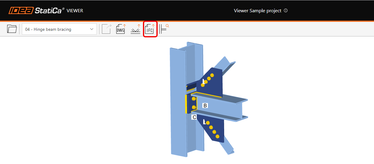
- Just upload the steel joint to our web application IDEA Statica Viewer.
- Click on the icon of IFC file and IFC of your joint will be automatically downloaded.
How to export your connection design into an IFC from IDEA StatiCa Checkbot
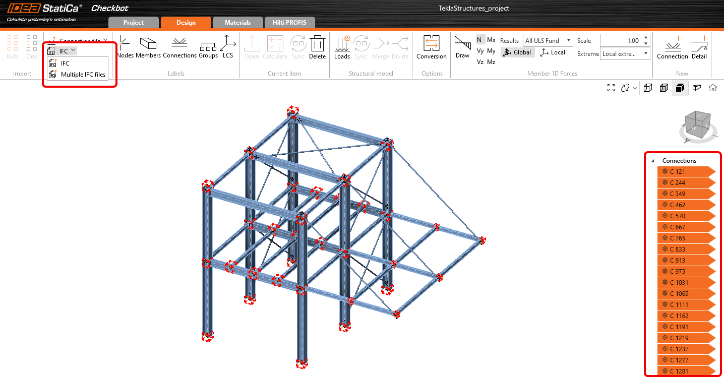
- Design your connections in IDEA StatiCa Connection and export all of them from Checkbot.
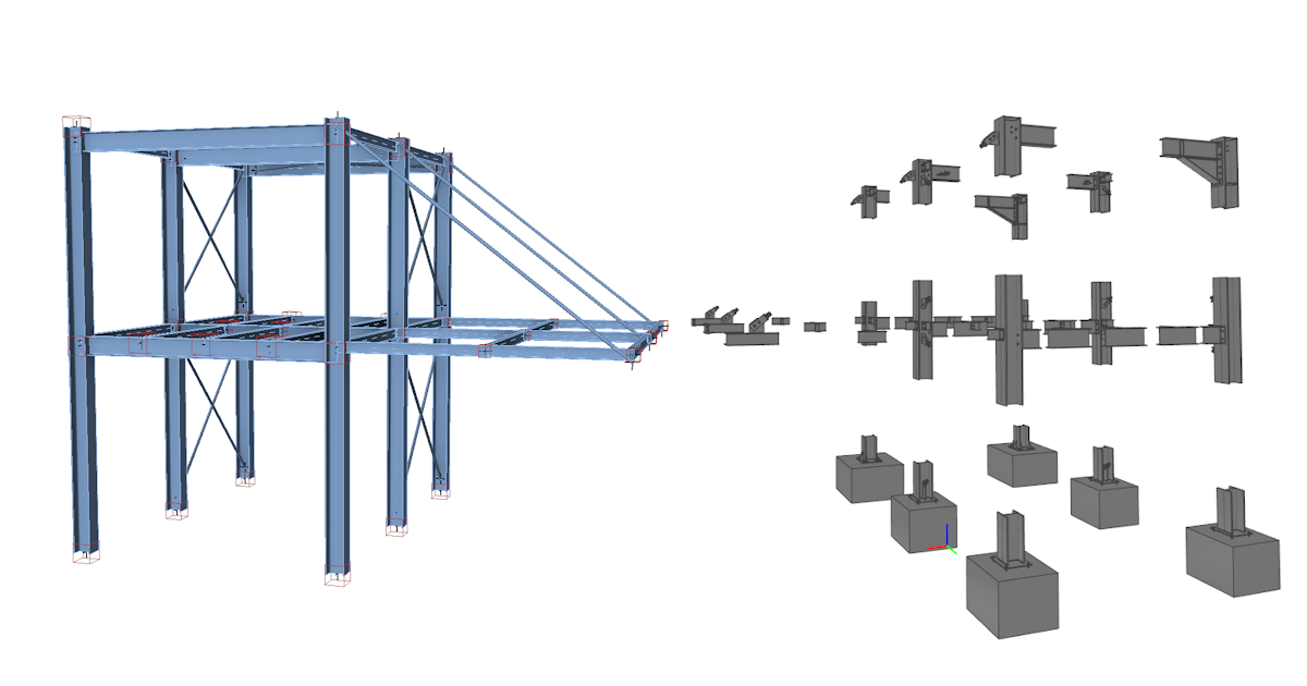
- Export the selected connections into a single file with global coordinates or each connection separately into individual IFC files.
- The Export button is accessible both from the ribbon in the Design tab and by right-clicking selected connections in the tree.
The IFC file includes:
- A geometrically accurate model of the connection, including bolts and welds.
- Basic information about cross-sections, bolts, welds, and materials.
- The model defined as an IFC2x3 coordination view
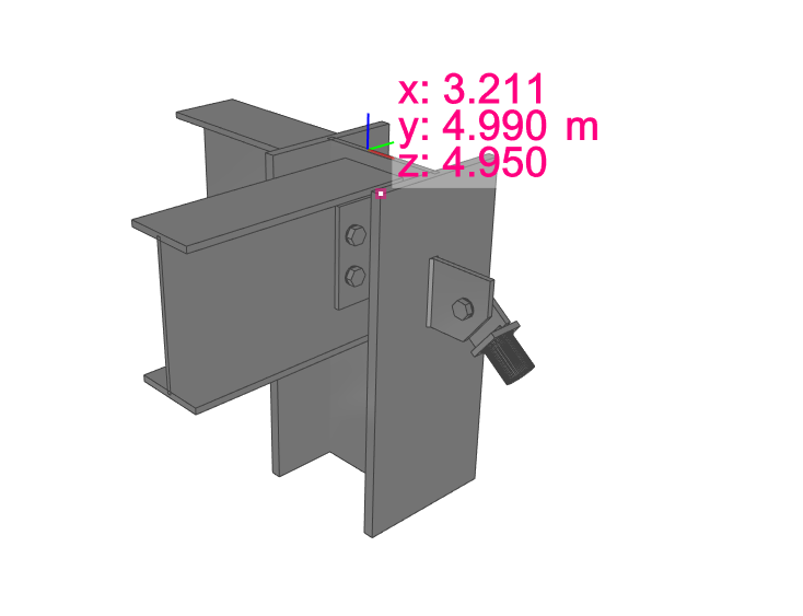
- When generating an IFC file from a connection created or exported through Checkbot, the export contains the global coordinates of the Connection Point – the real location of a connection in a project.
A visual representation of a connection
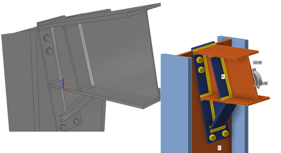
The IFC file can be imported to BIM/CAD tools (such as Tekla Structures, Autodesk Revit, etc.) as a visual representation of the connection model. This provides the detailer with a better understanding of the model. Opening the model in any IFC viewer software brings you a wholesome view and the possibility to create additional section views, cuts, and measurements.
IFC export improvements (since version 23.1.1)
Here you can find listed improvements and details about the IFC export in 23.1.1 patch:
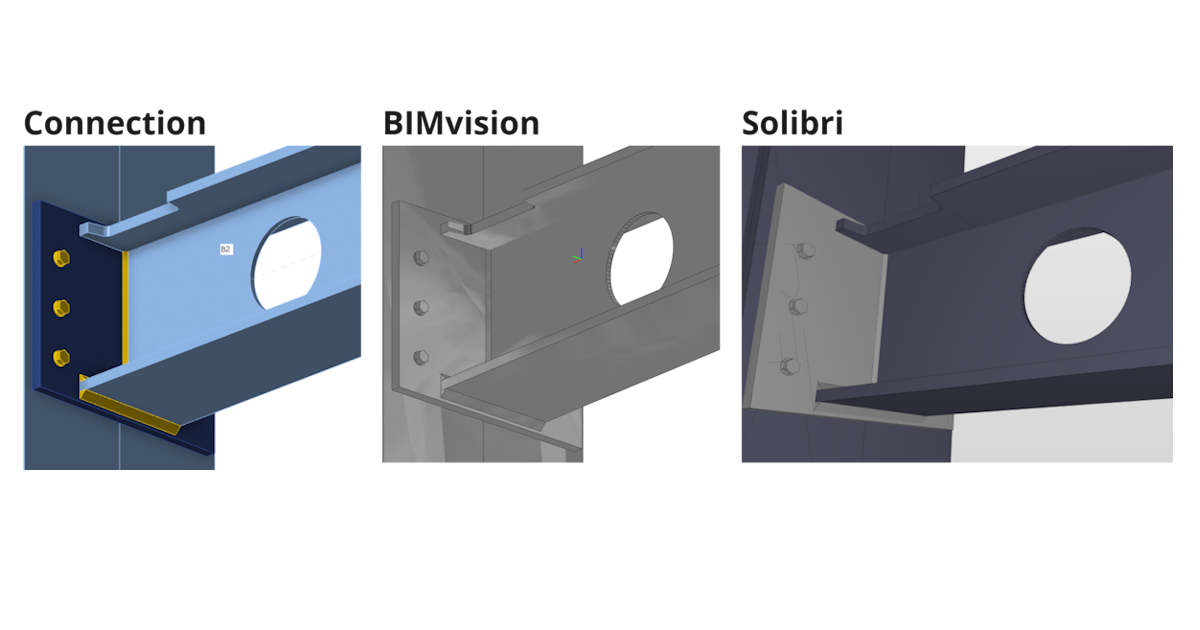
Supported and verified Viewers:
- BIMvision 2.27.3 and later
- Solibri 9.13.5.12 and later
- Autodesk Viewer (https://viewer.autodesk.com/)
Information about Cross sections and Materials
- Information about cross section and materials are contained in custom properties ("IDEA_CrossSection", "IDEA_MaterialSteel*" property sets).
Improved Openings, Notch-cutting
- Notches and Openings operations are supported fully for IFC export and are visualized correctly in IFC viewers (Solibri, BIMvision, and Autodesk viewer checked)
Negative volumes primarily export to IFC
- Negative Volumes with limitations
- In IDEA 23.1.1 added support for "Type" member Limitation - mirroring is not supported (planned for next iteration)
- In IDEA 23.1.1 added support for "Type" plate Limitation - negative plate is exported to IFC and has to be disabled in IFC viewer (planned for next iteration)
Improved bolt positioning during export
Improved IFC export of circular connection plates with unequal meshing
- Circular plates are exported correctly to the IFC
Validated IFC Syntax and Schema of IFC 2x3 by BuildingSmart validation tool
- https://validate.buildingsmart.org/ (note: referencing rules are not satisfied on purpose - referencing welds to multiple edges)
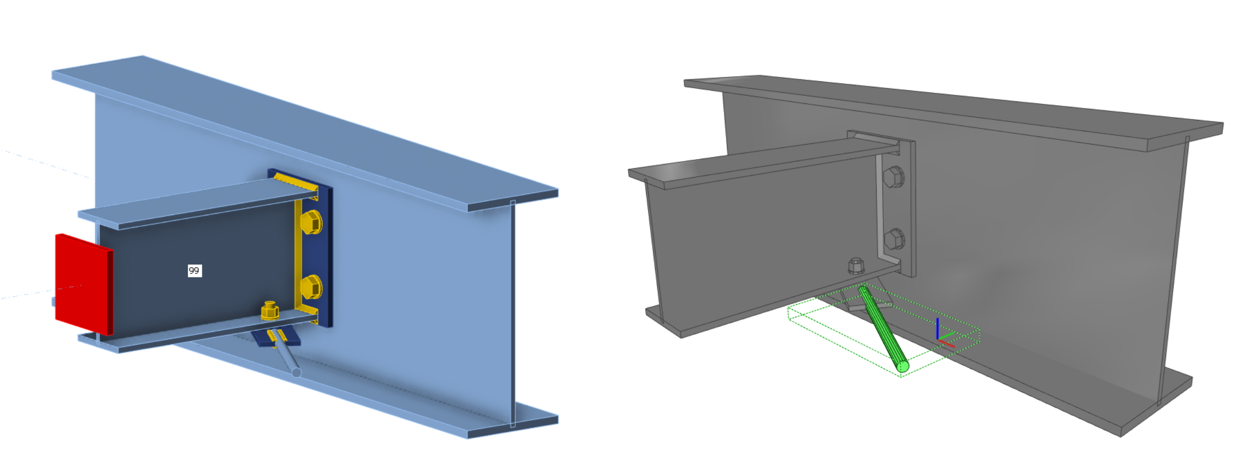
Rods can be exported to IFC from IDEA Statica
- Rods are supported for IFC export
Improved positioning of welds
- Welds are placed on the right edges according to the Connection model
Known limitations
IFC export from IDEA StatiCa Connection app and Viewer is optimized to export 3D geometry with parameters about materials and cross sections of contained objects.
Some software supports importing IFC objects and can even convert IFC objects to native design objects. We want to support this opportunity as much as possible but can’t optimize it for all.
Here, you can see the status of optimization for the following software:
Tekla Structures 2022, 2023
- IDEA IFC model can be imported
- Items can be converted to native objects “as item”
Autodesk Revit 2023, 2024
- IDEA IFC model can be imported as a linked project
Advance Steel 2023, 2024
- IDEA IFC can not be imported into Advance Steel (boundary representation geometry is not supported in Advance Steel)
IFC version
IFC 2x3 as coordination view is exported. (no option for settings)
Beams and plates
Beam and plates are exported as mashed geometry, so they do not act like a dimension object. (Advance Steel import limitation)
Bolt holes
Bolt holes are exported, but not all viewers and tools support viewing them.
Properties
Exported properties are SI units only.
Download the latest version of IDEA StatiCa and try all the features
Fire design – automatic temperature calculation (23.1)
Enhanced fire resistance calculations
We have enhanced the functionality released in version 22.1.
Using this method, the temperature in each plate is calculated separately. Fire is assumed to impact the whole connection model and all its surfaces at once. The temperatures of bolts and welds are safely assumed to be the same as the hottest connected plate.
Fire curve, resistance class, material degradation curves, and fire protection properties are set in the app Connection in Settings. Fire protection can be added uniformly to the whole joint.
Available in IDEA StatiCa Steel and IDEA StatiCa Complete editions.
Download the latest version of IDEA StatiCa and try all the features
- Member - rigid support member (RSM) and construction stages
- Welds - autodesign, input, warnings, visualization (since patch 23.0.2)
- Shear force position input and visualization (since patch 23.0.5)
- Yield strength reduction for high-strength steel hollow sections
- Warning for welds and bolts connecting the same plates (since patch 23.0.4)
- Singularity detection in Member (since patch 23.0.3)
- Filler plate (packing plate) recognition (since patch 23.0.3)
- Detailing improvements for bolts and welds in Eurocode (since patch 23.0.2)
- Limitations to checks of anchors (since patch 23.0.2)
Minor improvements in steel:
- New design of icons in the ribbon of the IDEA StatiCa Connection app
- Update of AISC steel and bolt grade materials for AISC360-22 (since patch 23.0.4)
- Notification of unavailable timber bolts check in results and report (since patch 23.0.1)
Test table
| filler plate | ||
| yield strength | ||
| stress-strain diagram |
News for Concrete and Prestressing
Every year, we introduce significant enhancements to facilitate the work of engineers worldwide. Version 23.1 is distinctive in that it comprises a new application, IDEA StatiCa 3D Detail, rather than being a mere enhancement to existing applications. This novel application enables the design of any spatially stressed area of reinforced concrete through the utilization of volume elements.
The Detail application has undergone a complete user interface refactoring, along with a new icon facelift, positioning it at the zenith of IDEA StatiCa's technological proficiency.
The latest enhancements are in the RCS application, where alterations in stress redistribution and redesign between concrete and concrete reinforcement have been observed in the interaction code-check. These updates are a testament to IDEA StatiCa's continued pursuit of technological innovation.
Highlights
Intuitive ribbon and navigation system for IDEA StatiCa Detail
Work in an attractive, clear, and simple-to-use graphical user interface (GUI) to make your concrete structural design faster!
Application layout
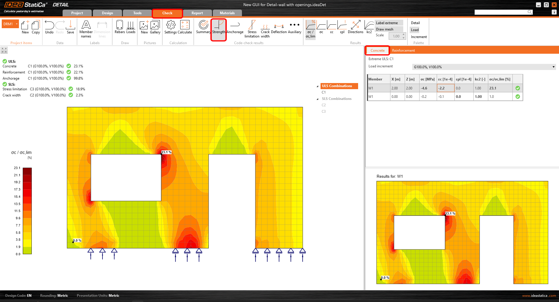
The graphical user interface of the Detail app is clear to understand and simple to use:
- Made up of six ribbon tabs – Project, Design, Tools, Check, Report, and Materials
- Triggering functionality or interacting with dialog boxes is done by command buttons in ribbon groups
- The scene displaying the user's concrete structure design and the navigation tree on the left takes up a lot of screen space as they are the most important components for the user
- The properties of a selected item (entities can be selected in the tree or in the scene) are presented in the Property grid on the right side of the app
- The footer at the bottom part of the app contains basic information about project settings, such as the design code, rounding units, presentation units, and a link to our webpage. By clicking these entities, the dialog window with relevant settings is open, allowing the definition of a selected group of parameters.
The project tab or backstage menu offers:
- Basic commands, such as New, Open, Save, and many more
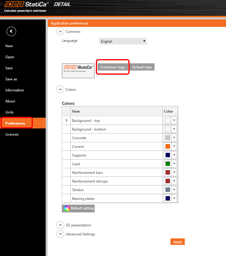
- Users can find application settings such as Units or Preferences here
Adding a new project entity:
- Each project can contain multiple project items
- A new project item is added using commands in the ribbon or in the backstage menu - Information tab
- It is possible to copy an existing item when working on similar structural designs
How to work in the Detail app
The graphical user interface is very intuitive and guides users on how to create their projects efficiently. Just follow the tabs in the ribbon step by step.
New project
- A wizard allows defining a project from a template (or user-defined type of structure) and setting initial material properties
Design
- Serves for designing the structural member, including the load and definition of reinforcement
- The geometry of the structure and reinforcement can be easily imported from the DXF files or added here by relevant buttons
- The tree of entities contains all entities defined in a model. Every entity in the tree has a set of carefully selected commands in the context menu. Entities in the tree can be grouped according to type or as a list of entities ordered sequentially.
- Great functionality that helps to design reinforcement has been developed. By deactivating the command "Draw rebar" in the ribbon, just the selected rebar entity is displayed in the scene and the rest is hidden. This helps with the detailing of a selected rebar without interfering with many other existing rebars.
Tools
- For all engineers struggling with designing a sufficient amount and layout of reinforcement, it allows calculation methods such as topology optimization and linear analysis to determine areas of the structure that require reinforcement
- The tree of entities is reduced and contains all existing rebars only
- The "Draw rebar" button, whose function is described in the section Design, can be used here, too
- For a reduced view on rebars described in the previous section (Design tab,) easy reinforcement design can be used in the Tools tab as well
Check
- The reduced navigation tree contains just combinations active for the code-check
- The type of code-check is selected by clicking the button in the ribbon (group Code-check results)
- Results for each material type are presented separately in the scene. Users can select what results are presented by selecting the tab Concrete, Reinforcement, or Tendon in the property grid
Report
- Several types of reports are supported – a brief report and a detailed one or a bill of materials if needed
- In the detailed report, users can arbitrarily define what results and outputs are presented in the final document, meaning a fully customizable report
- The report can be exported to a DOC or PDF file
Materials
- Check out the stress-strain diagram of each material, concrete, reinforcing, or prestressing steel
- Modify the material properties if necessary
Designing and checking concrete structures in the new GUI for the Detail application is fast and easy. How do we know? Because this user interface has worked very well for millions of customers using the Connection application, which is the basis of the new Detail GUI.
Download the latest version of IDEA StatiCa and try all the features
- Interaction code-check improvements in RCS (since patch 23.0.2)
- 3D Concrete use cases (BETA)
Minor improvements
- Unit unification for support stiffness
- Detail – DXF import improvements
- IOM – Extreme name description
News for BIM links and Cloud tools
BIM links with the major players in the Structural engineering field proved to be a strong tool for reducing the modeling time, decreasing the number of copy-paste errors, and solving the immense issues with data transferring. Because IDEA StatiCa follows the needs and workflows of its users the development continues in extending the functionalities of already working interconnections as well as the list of supported 3rd party logos we can cooperate with. Thanks to cooperating with other vendors we can now proudly introduce our new BIM link with SDS2 by Allplan and IDEA plugin for Rhino Grasshopper tool.
Do structural engineers want to invent the wheel again and again? Generally not. Why not use what already worked? Connection Library is the largest database of steel connections accessible online and can provide inspiration in cases where the designer is out of ideas.
- Connection Library - the largest database of steel connections
- Grasshopper Plugin for Connection API
- New BIM link with SDS2 app
- UX Improvements of Parametric design (since patch 23.0.2)
- BimApi solution for AXIS VM 7, Robot Structural Analysis (since patch 23.0.1)
- New Developer documentation website
If you want to check the compatibility with your particular application, just take a look at our list of actively supported versions in 23.1.
Plus, to help you in your endeavors, we have the newly revamped Campus. This educational resource provides you with an excellent selection of self-paced e-learning courses, each with the option of obtaining professional-level certification.
See the current list of solved incidents reported by our customers.
Full Release notes
Below, you can download the Release notes for IDEA StatiCa v23.1 in PDF.


