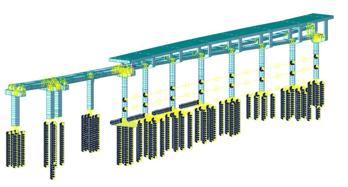
The MRT viaduct at Jurong East Integrated Transport Hub
About the project
This viaduct, also part of the Jurong Region Line (JRL), utilizes the innovative Floating Slab Track (FST) technology. It incorporates a double-pier system with full structural discontinuity to enhance noise and vibration control.
The superstructure includes two distinct types of LTA standard post-tensioned box girders, supported by unsymmetrical and unevenly loaded crossheads which are monolithically incorporated with the viaduct. Access openings are strategically located within these crossheads. The JRL roof columns, designed to withstand derailment loads, uphold the UIC777-2R standards.
An extensive track-structure interaction analysis was conducted adhering to UIC774-3R guidelines, taking the use of FST into account. The design of the viaduct is intricately intertwined with its construction sequence, the JRL roof structure above, and the building structure below. The viaduct's substructure is seamlessly connected to the building structure, with the pile cap forming an integral part of the B2 basement slab and the diaphragm wall of the West Wing structure.
Engineering challenges
One project challenge was designing the concrete crossheads, which included a shared crosshead between two single box girders carrying rails for different directions. The crosshead's two openings altered the typical behavior, necessitating the design of asymmetrical structures that would have been difficult to calculate manually.
The viaduct's design includes a landscape roof with columns supported on the viaduct crosshead, which is supported centrally and laterally. Additionally, it's unevenly loaded with heavy weight on one side and none on the other.
Solutions and results
Ei Sheng Hong's team successfully incorporated actual rebars into IDEA StatiCa Detail, generating valuable reports on their use. The software's automatic topology optimization calculated the strut-and-tie path, eliminating the need for time-consuming trial and error.
The calculation process, including verification, took just a day, a significant reduction from the months it would take manually. This efficiency facilitated the swift completion of the design and production of reinforcement drawings.
Before IDEA StatiCa, the team had to make many assumptions and simplifications in their designs to capture the structural behavior. So, IDEA StatiCa Detail was exactly the software they needed to overcome these limitations.
They were also impressed by the software's ability to perform simple analyses, offering the flexibility to extract necessary results and present them in a tabular format. This included various checks such as fatigue analysis.
Furthermore, because they only needed to model everything once, it saved time. With just a click, the results were displayed. The robust design checks they produced eliminated the need for additional questions or explanations.
About SMEC
For more than 70 years, SMEC has built a reputation as a trusted partner on major transport and energy infrastructure projects around the world. Our design leaders and specialist teams draw on deep expertise and experience delivering projects across a range of diverse environments, from some of the world’s most remote locations to some of the densest urban surroundings.


