Release notes IDEA StatiCa 23.1
Version 23.1 highlights
For steel, we did a lot in error-proofing and reporting – welds, load position, and detailing checks. IDEA StatiCa Member now has an input wizard and the ability to select rigid supports, dramatically speeding up your inputs and limiting errors. The fire design of connections also includes calculating the temperatures automatically.
IDEA StatiCa Connection now generates IFC files, including all bolts, welds, and materials. Structural engineers can share connection designs with detailers. Our cloud app, Connection Library, the world's largest online database of steel connections, allows downloading and reusing connection files in the desktop app.
IDEA StatiCa Detail, our solution for the structural design of concrete walls and details, has undergone a complete user interface refactoring. New facelift of icons and ribbon, new modeling commands, better 3D scene, and more reporting options, all of which make your work much faster.
Steel connection design
Esportazione di un file IFC da IDEA StatiCa Connection
Un modello IFC equivale a più di una dozzina di disegni
In qualità di progettista, la modellazione di un progetto di connessione complesso, o anche semplice, in base ai disegni 2D forniti da un ingegnere strutturale, può diventare complicata e creare spazio per gli errori. Pertanto, è importante condividere il maggior numero di informazioni possibile tra le due professioni. Quindi, perché non utilizzare un formato riconosciuto da tutti i software BIM del settore? Un IFC fornisce una rappresentazione 3D della connessione, che può essere collegata a Tekla, Revit, ecc. e ai visualizzatori IFC.
Come esportare il progetto di connessione in IFC
Basta un clic!
- Progetta il tuo giunto in acciaio in IDEA StatiCa Connection e passa alla scheda Relazione.
- Fai clic sull'icona di esportazione IFC e il gioco è fatto!
Puoi esportare le connessioni in IFC anche se non utilizzi l'applicazione desktop!
- Basta caricare il giunto in acciaio nell'applicazione web IDEA Statica Viewer.
- Clicca sull'icona del file IFC e l'IFC del tuo giunto verrà scaricato automaticamente.
Il file IFC include:
- Un modello geometricamente accurato della connessione, compresi i bulloni e le saldature.
- Informazioni di base su sezioni, bulloni, saldature e materiali.
- Il modello definito come vista di coordinamento IFC2x3.
La rappresentazione grafica di una connessione
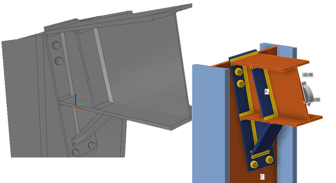
Il file IFC può essere importato in strumenti BIM/CAD (come Tekla Structures, Autodesk Revit, ecc.) come rappresentazione grafica del modello di connessione. Ciò consente al progettista di comprendere meglio il modello. Aprendo il modello in qualsiasi software di visualizzazione IFC si ottiene una visione completa e la possibilità di creare viste di sezione, tagli e misure aggiuntive.
Miglioramenti alle esportazioni IFC
Qui sono elencati i miglioramenti e i dettagli relativi all'esportazione IFC nella patch 23.1.1:
Visualizzatori supportati e verificati:
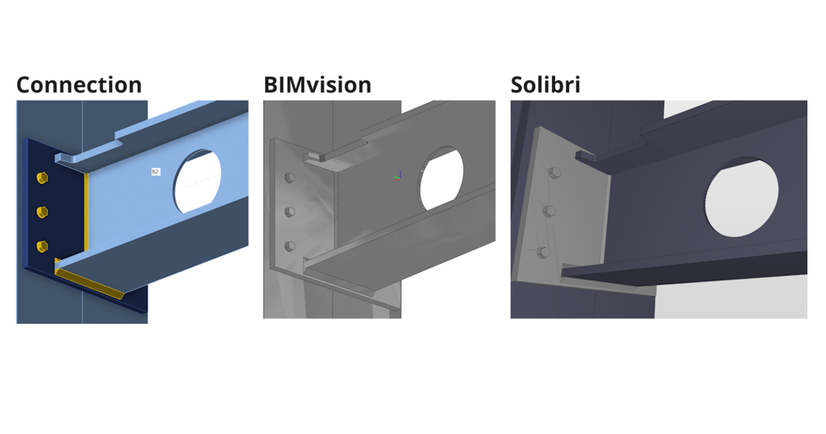
- BIMvision 2.27.3 e versioni successive
- Solibri 9.13.5.12 e successivi
- Autodesk Viewer(https://viewer.autodesk.com/)
Informazioni su sezioni e materiali
- Le informazioni sulla sezione trasversale e sui materiali sono contenute nelle proprietà personalizzate (set di proprietà "IDEA_CrossSection", "IDEA_MaterialSteel*").
Aperture, taglio a intaglio migliorate
- Le operazioni di intaglio e apertura sono pienamente supportate per l'esportazione IFC e vengono visualizzate correttamente nei visualizzatori IFC (Solibri, BIMvision e Autodesk viewer controllati).
I volumi negativi vengono esportati principalmente in IFC
- Volumi negativi con limitazioni
- In IDEA 23.1.1 è stato aggiunto il supporto per il membro "Tipo" Limitazione - il mirroring non è supportato (previsto per la prossima iterazione)
- In IDEA 23.1.1 aggiunto il supporto per la piastra "Tipo" Limitazione - la piastra negativa viene esportata in IFC e deve essere disabilitata nel visualizzatore IFC (prevista per la prossima iterazione)
Miglioramento del posizionamento dei bulloni durante l'esportazione
Migliorata l'esportazione in IFC di piastre di connessione circolari con mesh disuguale
- Le piastre circolari vengono esportate correttamente nell'IFC
Sintassi e schema IFC di IFC 2x3 convalidati dallo strumento di convalida BuildingSmart
- https://validate.buildingsmart.org/ (nota: le regole di riferimento non sono soddisfatte di proposito - riferimento delle saldature a più bordi)
Le aste possono essere esportate in IFC da IDEA Statica
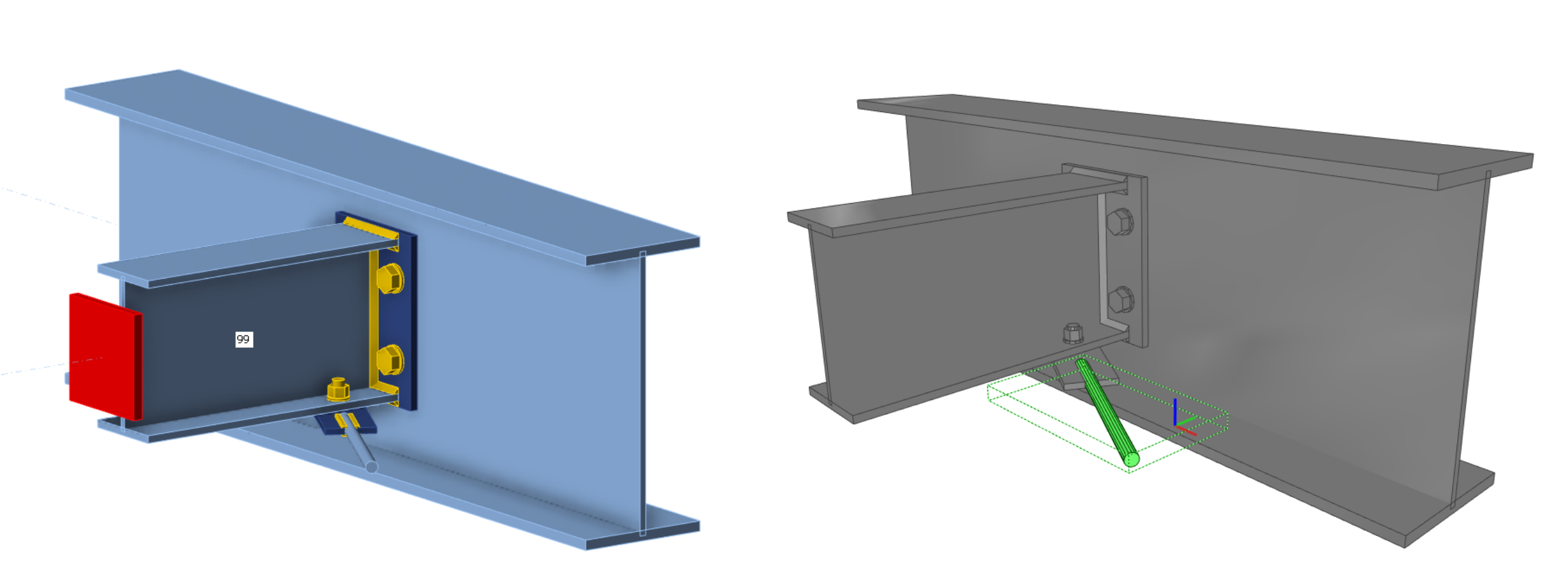
- Le aste con sezione tondo pieno sono supportate per l'esportazione in IFC
Miglioramento del posizionamento delle saldature
- Le saldature sono posizionate sui bordi giusti in base al modello di Connessione
Limitazioni conosciute
L'esportazione IFC dall'applicazione e dal visualizzatore IDEA StatiCa Connection è ottimizzata per esportare la geometria 3D con i parametri relativi ai materiali e alle sezioni trasversali degli oggetti contenuti.
Alcuni software supportano l'importazione di oggetti IFC e possono persino convertire gli oggetti IFC in oggetti di progettazione nativi. Vogliamo supportare il più possibile questa opportunità, ma non possiamo ottimizzarla per tutti.
Qui è possibile vedere lo stato di ottimizzazione per i seguenti software:
Tekla Structures 2022, 2023
- È possibile importare il modello IDEA IFC
- Gli elementi possono essere convertiti in oggetti nativi "come elemento".
Autodesk Revit 2023, 2024
- Il modello IDEA IFC può essere importato come progetto collegato
Advance Steel 2023, 2024
- IDEA IFC non può essere importato in Advance Steel (la geometria di rappresentazione dei confini non è supportata in Advance Steel)
Versione IFC
Viene esportato IFC 2x3 come vista di coordinamento. (nessuna opzione per le impostazioni)
Travi e piastre
Le travi e le piastre vengono esportate come geometria schiacciata, quindi non si comportano come un oggetto di dimensione. (Limitazione all'importazione di Advance Steel)
Fori per bulloni
I fori dei bulloni vengono esportati, ma non tutti i visualizzatori e gli strumenti ne supportano la visualizzazione.
Proprietà
Le proprietà esportate sono solo unità SI.
Scarica e prova le funzionalità di IDEA StatiCa
Progettazione antincendio - calcolo automatico della temperatura (23.1)
Calcoli di resistenza al fuoco migliorati
Abbiamo migliorato la funzionalità rilasciata nella versione 22.1.
Con questo metodo, la temperatura in ogni piastra viene calcolata separatamente. Si presume che il fuoco colpisca l'intero modello di connessione e tutte le sue superfici contemporaneamente. Si presume che le temperature dei bulloni e delle saldature siano uguali a quelle della piastra collegata più calda.
La curva di incendio, la classe di resistenza, le curve di degrado dei materiali e le proprietà di protezione antincendio sono impostate nell'app IDEA Connection nella finestra Impostazioni. La protezione antincendio può essere aggiunta uniformemente all'intero giunto.
Disponibile nelle edizioni IDEA StatiCa Steel e IDEA StatiCa Complete.
Scarica la nuova versione di IDEA StatiCa e prova tutte le funzionalità
Welds – autodesign, input, warnings, visualization
User-defined welding electrodes
Weld material is an editable item in the MPRL (Material and Product Range Library). This means you can define the welding electrodes independently on a steel grade of connected plates.
To add a user-defined welding material, go to the tab Materials, add a Weld material, and Edit its properties.
Also, the correlation factor βw can be modified from the default value of 0.8 to match with values for, e.g., stainless steel requirements (βw = 1.0 for steel weld strength lower than 360 MPa).
You can then assign the welding electrode material in a combo box of any weld of any operation. Alternatively, you can add a new weld material.
Check tables and the report are expanded to always contain information about the welding electrodes and their parameters.
Autodesign of welds to full-strength
This feature allows users to optimize the weld size based on the welded plate strength. This shortens the design time and ensures safe weld size for all welds in the connection project.
You can run the Autodesign weld to full-strength algorithm for all welds within the connection project at once via the right mouse button on Operations in the tree menu.
For the algorithm, the assumptions are that the plate is loaded in tension (more dangerous for weld designs) and the weld length is the same as the connected plate edge length. Plate strength in tension is taken as the weld strength perpendicularly loaded, and the weld size is then derived. The inputs are:
- Thickness of the connected plate by edge (or the thinner plate in edge-to-edge case)
- Yield strength of connected plate material
- Ultimate strength of weld material
- Other weld parameters (factors, coefficients, e.g., βw)
- Partial safety factors for plate material
- Partial safety factors for weld material
Weld throat thickness or leg size value rounding can be set in Settings, Pre-design, and Weld size.
Estimation of a weld's overall capacity
In the results tab for welds, there are two utilization ratios listed. The Ut (stress utilization) shows the utilization value of the most stressed finite element of the whole weld (peak value), while the Utc (weld capacity utilization) shows the utilization of the whole weld and thus gives the user information about the remaining weld capacity.
Since stress distribution in welds in FEM-based models varies uncertainly based on the applied load, it is not simple to determine the remaining capacity as a linear function. With an increment of applied load, the change in weld stress distribution can be very dramatic.
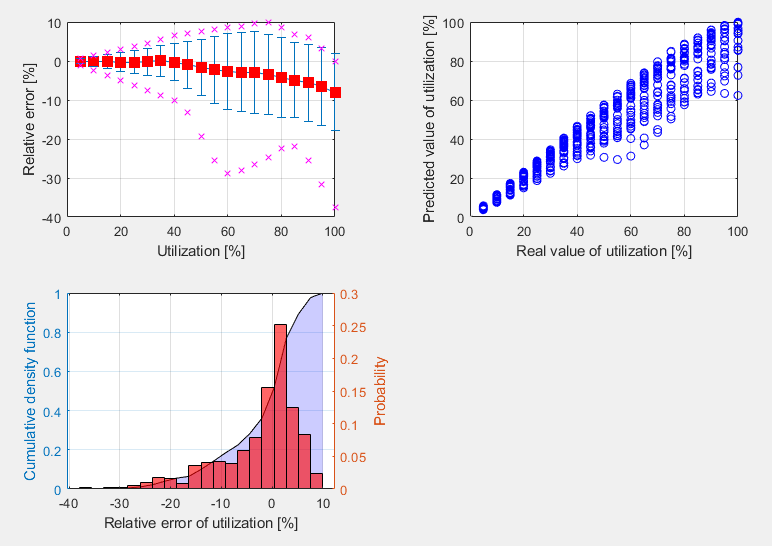
The calculation of Utc uses a machine-learning estimation function. Based on learning from a vast number of welded connection models and various load scenarios, the algorithm can accurately predict the remaining weld capacity. The number is displayed in Check, in the Welds tab in the Utc column.
This functionality is the first successful use of AI and machine learning to determine the capacity of welds. And what's best is that the application can do it within a 10% threshold! Which can be considered an excellent result.
This feature is limited to projects in Eurocode.
General weld highlighted in the 3D scene
There is a simple improvement in the 3D scene of the Connection app for better orientation, especially in bigger connection models imported via BIM links from CAD applications.
When a General weld or contact operation is selected, the weld in the 3D scene is highlighted in orange (by default).
Warning for electrodes stronger than plates
When the Detailing check is activated in the Code setup of the Connection app, users get a warning if a welding electrode material is stronger than the welded plates. This helps to ensure design safety standards.
This applies to Eurocode (EN) and Indian standard (IS), which contain clauses defining that weld strength is determined by the smaller ultimate strength of connected plates and requirements that the added material of welding electrodes must be stronger than the parent material (EN 1993-1-8 – 4.5.3.2 and IS 800:2007 - 10.5.7.1.1).
Butt weld FEM model improvement
The finite element model of butt welds has been updated. The model of butt welds is now similar to the model of fillet welds, which makes it easier for the automatic entity generator to create a butt weld generation under certain conditions, especially for hollow sections.
Improved weld check visualization
Weld checking using a finite element method differs from traditional design calculations. In traditional calculations, small eccentricities, deformations, torsions, and Poisson coefficients, etc., may be neglected.
Stress components are now shown:
- σꓕ
- τꓕ
- τ‖
These stresses are used in all codes for further weld evaluation.
Equivalent stress is colored grey/green/orange/red according to Warning and Optimal check level (editable in Code setup) for higher clarity.
This improved functionality helps engineers understand the stresses in welded connections.
Available in IDEA StatiCa Steel and IDEA StatiCa Complete editions.
Scarica la nuova versione di IDEA StatiCa e prova tutte le funzionalità
The coherent icons and ribbon of IDEA StatiCa Connection
As trends evolve, we ensure the visual style of our applications meet user needs. In IDEA StatiCa Connection, the icons were designed to clearly represent their function, to look coherent, and to navigate easily while working in the application.
A set of icons has been designed specifically for each workflow tab (Design, Check, Report, Materials).
Available in IDEA StatiCa Steel and IDEA StatiCa Complete editions.
Scarica la nuova versione di IDEA StatiCa e prova tutte le funzionalità
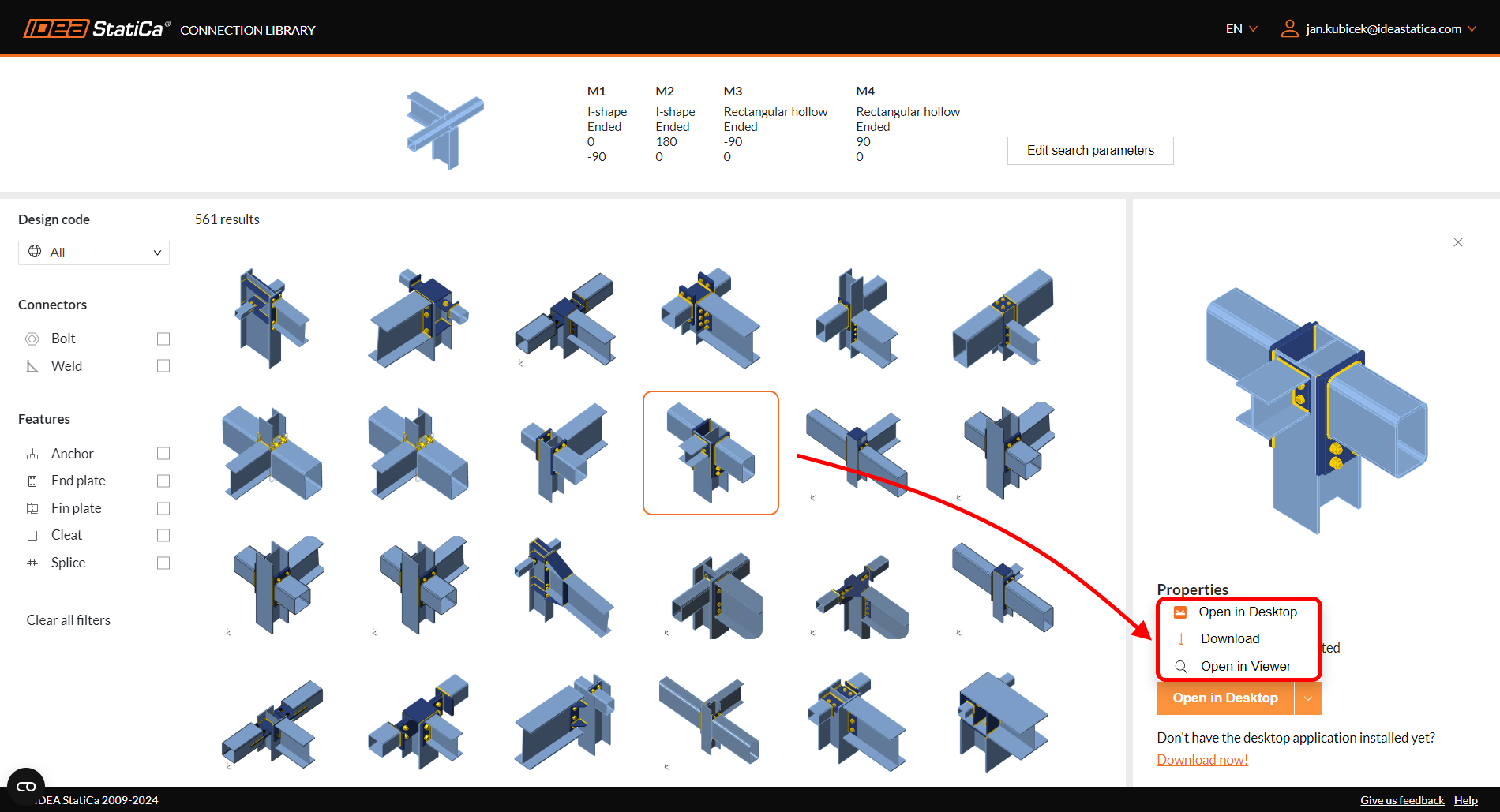
Connection Library - il più grande database di connessioni in acciaio scaricabili
D'ora in poi saprai a chi rivolgerti per trovare ispirazione. Basta cercare la pagina connectionlibrary.ideastatica.com nel browser di Internet.
Con la Connection Library è possibile sfogliare gli esempi con la geometria desiderata e trovare l'ispirazione in pochi secondi! L'utilizzo dell'applicazione è semplice e intuitivo! Il database di base è composto da 700.000 progetti e si amplia ogni giorno.
Come funziona
Connection Library è un'applicazione web che consente agli utenti di trovare ispirazione fornendo loro un database pubblico di migliaia di connessioni disponibili. Gli utenti possono quindi utilizzare le connessioni fornite nell'app Connection o condividere i risultati della ricerca con altri, nonché scaricare le connessioni e utilizzarle come punto di partenza per i loro progetti.
L'applicazione è composta da due pagine: la pagina di input e la pagina dei risultati:
- Nella pagina di input, l'utente può definire la connessione che sta cercando utilizzando i parametri di input disponibili. È disponibile una scena 3D, in modo da rendere chiaro l'aspetto dell'input di ricerca.
- Nella pagina dei risultati, l'utente ha a disposizione tutti i risultati relativi all'input immesso in precedenza. L'utente può esaminare i risultati della ricerca in modo più dettagliato, utilizzare i filtri per restringere la ricerca o tornare alla pagina di immissione e modificare l'immissione.
L'utente può accedere ai dettagli della connessione nella pagina dei risultati dopo aver effettuato l'accesso. Se l'utente non ha ancora un account, è possibile registrarsi. In questo caso, l'utente viene reindirizzato a una pagina in cui può registrarsi e ottenere un account con licenza Basic. Nei dettagli della connessione, l'utente ha la possibilità di scaricare una licenza di prova.
Il design selezionato può essere utilizzato ulteriormente:
- Aprire direttamente nell'applicazione Desktop
- Scaricare il file in formato .ideacon
- Aprire nel Viewer
Le fonti di questo database sono i modelli di connessione creati e condivisi dagli utenti in un'altra applicazione web - IDEA StatiCa Viewer.
Per saperne di più sull'uso e sui vantaggi del database cloud Connection Library, potete consultare questo post del blog dedicato a Come farsi ispirare durante la progettazione di connessioni in acciaio.
Scarica la nuova versione di IDEA StatiCa e prova tutte le funzionalità
Shear force position input and visualization
An option for setting the shear force position in a connection has been implemented to ensure smoother modeling. On top of that, you can see the bending moment diagram due to unit shear force immediately!
Let's have a look at the features one by one.
Shear force position at the member face
In many cases, the shear force position is assumed at the member face. You can face this situation when designing a connection with, e.g., a cleat, a short end plate, a flexible support, etc. We have developed a way of inputting the shear force position so you can become more efficient and get rid of tedious, repetitive work.
You can set the position using the Connected member face functionality. The software will set it automatically according to the connected member's surface. That means no more manual adjusting using coordinates. And with the change of cross-sections, the position is still kept.
How does it work? Simply select the member for which you want to set the force position, and select the Connected member face option in the Forces in section under Model in the property tab. It is recommended to always select the connected member manually.
The method and position are also shown in the report.
A better way of shear force position visualization
The Connection application now shows you the value of the bending moment from the unit shear force Vz=-1 for every modeled connection. The unit is according to the unit setting (e.g., Vz= -1 kN or -1 kip). The bending moment also respects the unit settings (e.g., kNm or kip-ft).
The diagram can be shown in Transparent or Wireframe visualization mode, i.e., select the member for which you want to see the diagram, and use one of these modes.
The real moment diagram using the load effects input is still shown in the Load effects section.
Available in IDEA StatiCa Steel and IDEA StatiCa Complete editions.
Scarica la nuova versione di IDEA StatiCa e prova tutte le funzionalità
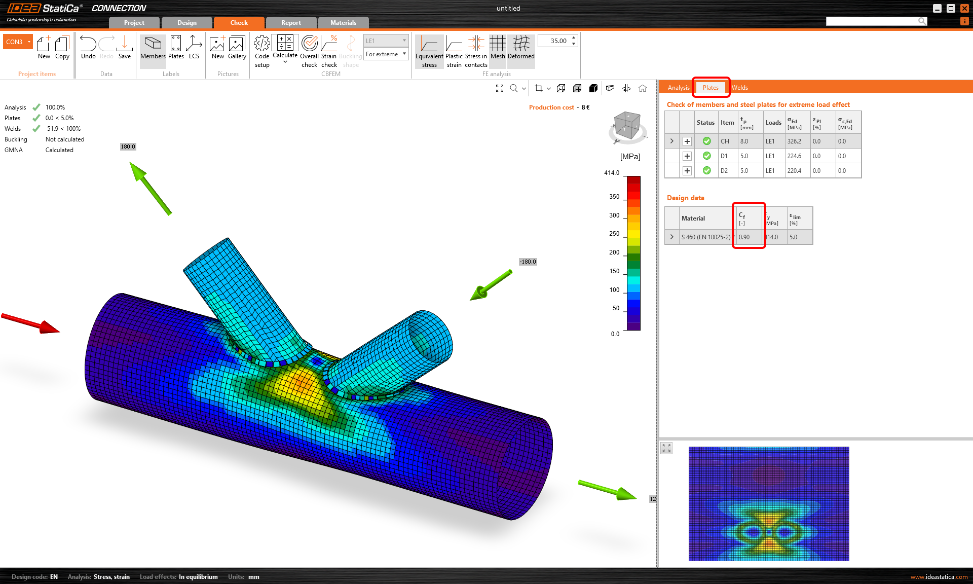
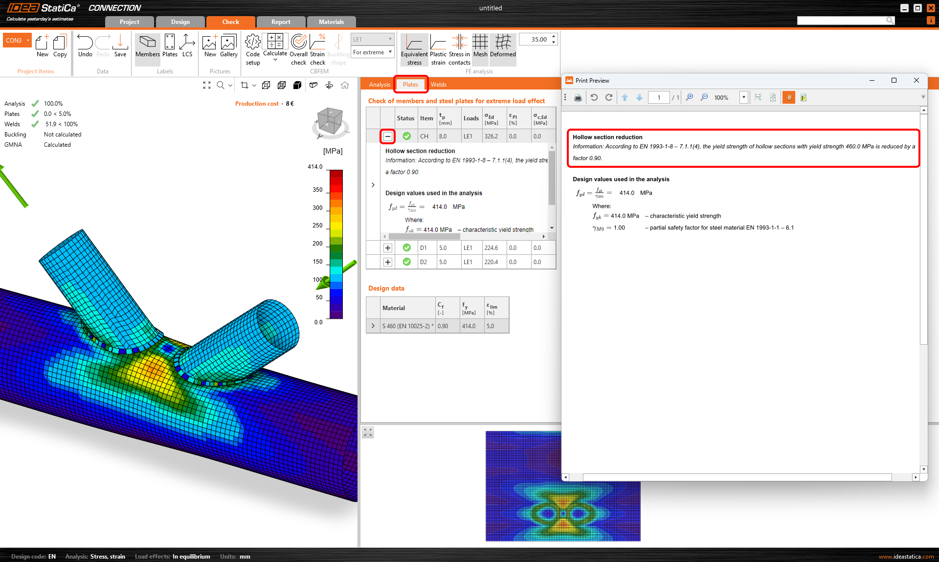
Riduzione della resistenza allo snervamento per sezioni cave in acciaio ad alta resistenza
L'acciaio ad alta resistenza è più fragile dell'acciaio dolce. La resistenza dei modi di rottura dei giunti a sezione cava dovrebbe essere ridotta per gli acciai ad alta resistenza di un fattore corrispondente, secondo la norma EN 1993-1-8, Cl. 7.1.1 (4). Inoltre, lo stesso è indicato nella prEN 1993-1-8:2023 - Tabella 9.1, che è la nuova generazione di codice di progettazione.
In IDEA StatiCa, la resistenza dei giunti a sezione cava è determinata dalla deformazione plastica del 5% delle piastre. Una riduzione affidabile può essere ottenuta diminuendo di conseguenza la resistenza allo snervamento dell'acciaio.
La resistenza allo snervamento dei giunti a sezione cava realizzati in CHS o RHS con acciaio ad alta resistenza viene automaticamente ridotta del fattore di riduzione previsto dal codice. In questo modo si evita di trascurare involontariamente la riduzione, che potrebbe portare a una progettazione non sicura.
Il valore del fattore di riduzione viene visualizzato nella tabella dei dati di progetto nella sezione Verifica e nella descrizione della verifica delle piastre.
Disponibile in IDEA StatiCa Steel e IDEA StatiCa Complete.
Scarica la nuova versione di IDEA StatiCa e prova tutte le funzionalità
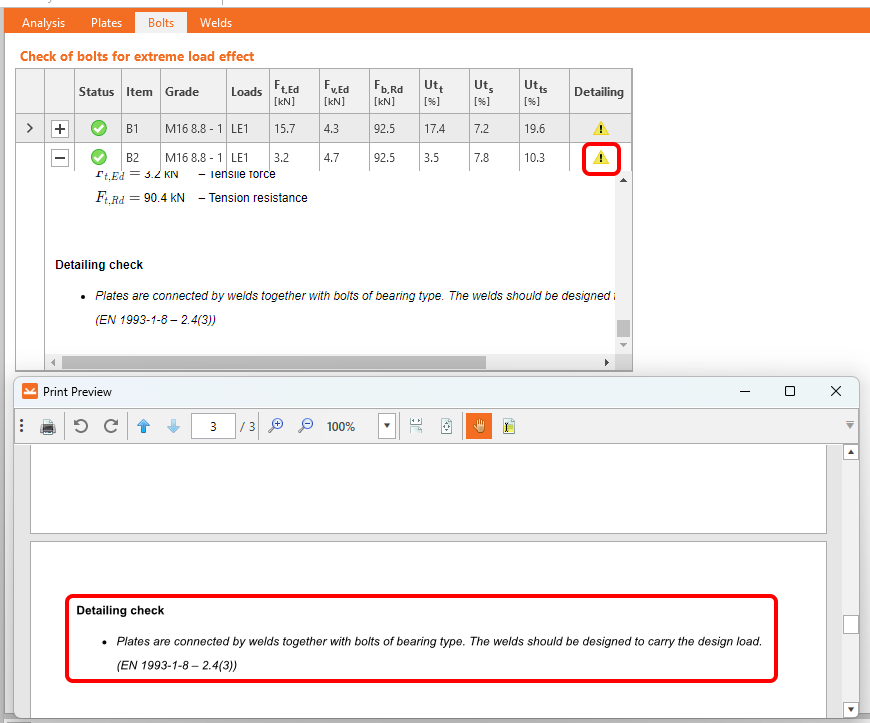
Warnings for welds and bolts connecting the same plates
The detailing check for bolts and welds in the IDEA StatiCa Connection application has been extended by new rules according to all available codes together with references for Eurocode.
Two potential situations for which you receive a warning message in the Detailing check are distinguished:
- The same two plates are connected by both bolts and welds.
- The same two plates are connected by both bolts and preloaded bolts.
1. Bearing bolts and welds
If the same two plates are connected by bolts with shear force transfer set as Bearing – tension/shear interaction and welds, a detailing warning message displays in the Bolts check section.
2. Bearing bolts and preloaded bolts
If the same two plates are connected by bolts with shear force transfer set as Bearing – tension/shear interaction and bolts with shear force transfer set as Friction (preloaded bolts), a detailing warning message displays in the Preloaded bolts check section.
Why pay attention?
Using the above-mentioned approaches in your projects might affect the connection.
The warning message provides you with recommendations. Raised attention to the design is advised but not unconditionally necessary. In other words, the connection won't fail because of the issue, however, you risk an incorrect design.
Moreover, such workflows are not allowed by codes.
Available in IDEA StatiCa Steel and IDEA StatiCa Complete editions.
Scarica la nuova versione di IDEA StatiCa e prova tutte le funzionalità
Filler plate (packing plate) recognition
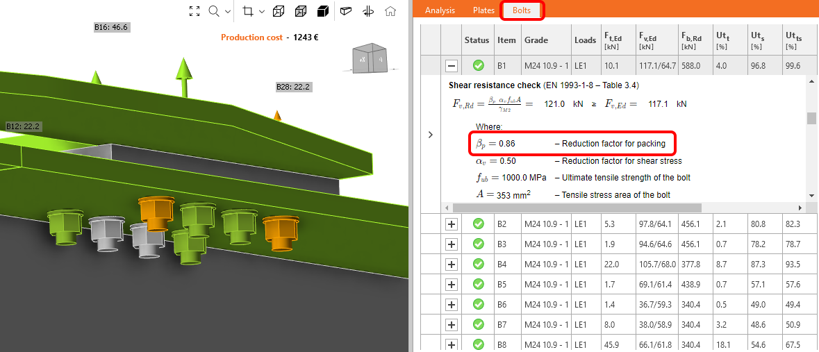
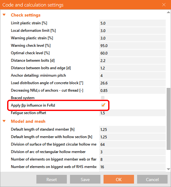
When a filler plate (packing plate) is designed in a bolted connection, the reduction factor βp for the Shear resistance check should be applied using a new algorithm for filler plate recognition.
The reduction factor βp is taken into account and displayed in the check equation by default. It can be turned off in the Code setup.
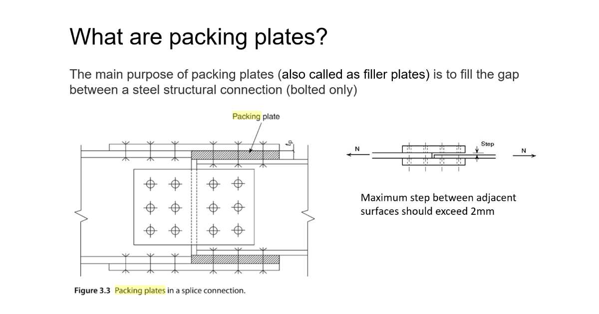
Filler plates (in other terminology, packing plates) are used to fill the gap in bolted connections when aligning connections of plates with different thicknesses.
Available in IDEA StatiCa Steel and IDEA StatiCa Complete editions.
Scarica la nuova versione di IDEA StatiCa e prova tutte le funzionalità
Detailing improvements for bolts and welds in Eurocode
Satisfying detailing checks are essential for a correct and safe design.
The detailing checks for bolts and welds in the IDEA StatiCa Connection application have been extended by new rules according to Eurocode.
Implemented range of validity rules:
Bolts according to EN 1993-1-8 and EN 1993-1-3
- Minimum plate thickness
- Ductility check
Welds according to EN 1993-1-8
- Minimum plate thickness
- Minimum weld throat thickness of fillet welds
- Ductility check
The application distinguishes four types of detailing messages:
- OK - represented by the green tick button
This indicates that the model complied with all necessary matters according to the standard, and the connection is designed safely.
- Error - represented by the red cross icon
Error alerts you to serious non-compliance with the requirements of the standard, and you have to pay attention to the design of the corresponding component.
- Warning - represented by the yellow triangle with an exclamation point icon
Warning message provides you with recommendations, e.g., based on practical experience. Raised attention to the design is advised but not unconditionally necessary.
- Info - represented by the blue info icon
Info message has an informative character about less common issues to check, e.g., ductility.
Individual messages can be seen in detail in corresponding check tables under formulas in the Check section or in the Report.
If there is more than one detailing message of a different type for one item, then the resulting status of messages of the particular item is determined by the message of the highest importance.
The "Error" message has the highest importance, the "Info" message has the lowest one.
The theory, including all corresponding formulas for the above-mentioned checks, is described in part of the theoretical background - Check of steel connection components (EN).
Available in IDEA StatiCa Steel and IDEA StatiCa Complete editions.
Download the new version of IDEA StatiCa and try all the features
Limitations to checks of anchors
Eurocode
Anchor type: Straight
Message:
The following checks of anchors loaded in tension are not provided and should be checked using the information in the relevant European Technical Product Specification:
- Pull-out failure of fastener (for post-installed mechanical anchors) – EN 1992-4, Cl. 7.2.1.5,
- Combined pull-out and concrete failure (for post-installed bonded anchors) – EN 1992-4, Cl. 7.2.1.6,
- Concrete splitting failure – EN 1992-4, Cl. 7.2.1.7.
Concrete blow-out failure is provided only for anchors with washer plates.
Anchor type: Washer plate
Message:
Concrete splitting failure should be determined by EN 1992-4, Cl. 7.2.1.7. The information from relevant European Technical Product Specification is missing.
AISC (LRFD)
Anchor type: Straight
Message:
The following checks of anchors loaded in tension are not provided and should be checked using the information in the relevant Technical Product Specification (based on the 5 % fractile of tests performed and evaluated according to ACI 355.2):
- Pull-out failure of fastener (for post-installed mechanical anchors) – ACI 318-19: 17.6.3,
- Bond strength of adhesive anchor (for post-installed bonded anchors) – ACI 318-19: 17.6.5,
- Concrete splitting failure during installation should be evaluated by ACI 355.2 requirements.
Concrete blow-out failure is provided only for anchors with washer plates.
Anchor type: Washer plate
Message:
Concrete splitting failure during installation is not checked and should be evaluated by ACI 355.2 requirements.
CSA
Anchor type: Straight
Message:
The following checks of anchors loaded in tension are not provided and should be checked using the information in the relevant Technical Product Specification (based on the 5 percent fractile of tests):
- Pull-out failure of fastener (for post-installed mechanical anchors) – CSA A23.3-14: D.6.3,
- Bond strength of adhesive anchor (for post-installed bonded anchors) – CSA A23.3-14: D.6.5.
Concrete blow-out failure is provided only for anchors with washer plates. Anchors shall satisfy the required edge distances, spacings, and thicknesses to preclude splitting failure as required by CSA A23.3-14: D.9.
Anchor type: Washer plate
Message:
Anchors shall satisfy the required edge distances, spacings, and thicknesses to preclude splitting failure as required by CSA A23.3-14: D.9.
AS
Anchor type: Straight
Message:
The following checks of anchors loaded in tension are not provided and should be checked using the information in the relevant Technical Product Specification (testing according to AS 5216:2018: Appendix A):
- Pull-out failure of fastener (for post-installed mechanical anchors) – AS 5216:2018: 6.2.4,
- Combined pull-out and concrete cone failure (for post-installed bonded anchors) – AS 5216:2018: 6.2.5,
- Concrete splitting failure – AS 5216:2018: 6.2.6.
Concrete blow-out failure is provided only for anchors with washer plates.
Anchor type: Washer plate
Message:
Concrete splitting failure should be determined by AS 5216:2018: 6.2.6. The information from relevant Technical Product Specifications (testing according to AS 5216:2018: Appendix A) is missing.
Available in IDEA StatiCa Steel and IDEA StatiCa Complete editions.
Download the new version of IDEA StatiCa and try all the features
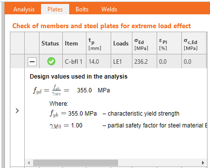
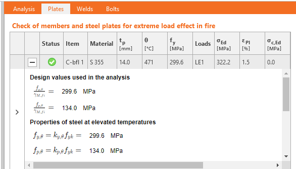
Detailed calculation of connection design material values displayed for plates
For different types of analysis, the design material parameters' values change according to the particular design code's requirements.
If the user wants to display and check the design values going into the analysis calculations, everything can be found in the result table for Plates. Simply click the 'plus' button to display more comprehensive information about the analysis, such as material reduction for hollow sections or specific steel parameters for stress-strain analysis, capacity design, fire design, or horizontal tying analysis.
Available in IDEA StatiCa Steel and IDEA StatiCa Complete editions.
Scarica la nuova versione di IDEA StatiCa e prova tutte le funzionalità
It is also worth mentioning that we have updated steel and bolt grade materials for AISC360-22 in the application. (since patch 23.0.4)
Steel member design
Detailed calculation of connection design material values displayed for plates
For different types of analysis, the design material parameters' values change according to the particular design code's requirements.
If the user wants to display and check the design values going into the analysis calculations, everything can be found in the result table for Plates. Simply click the 'plus' button to display more comprehensive information about the analysis, such as material reduction for hollow sections or specific steel parameters for stress-strain analysis, capacity design, fire design, or horizontal tying analysis.
Available in IDEA StatiCa Steel and IDEA StatiCa Complete editions.
Scarica la nuova versione di IDEA StatiCa e prova tutte le funzionalità
Strengthening of existing steel members
Construction stages and strengthening
Construction stages (known as Preload in the Member application) are used when, say, an engineer needs to check a member based on a new load distribution against an existing load pattern. Using this method, specific and targeted strengthening works can be designed.
Strengthening a building, rather than demolition, can be a complex solution, which is why this method has been introduced. It aims to allow design teams to formulate a strategy that saves buildings and reduces CO2 emissions. There are several examples in engineering where this is required: where solar PV panels are used on existing roofs, leading to increased loading and uplift, or re-modeling of retail premises where stairs and openings are never in the right place.
Define a new Check type of the pre-load to allow the software to introduce additional loading after the required ULS loading checks have been completed. Thanks to this, you can clearly see pass/fail results, including the, e.g., stress in the existing structure, and in the plates of the added strengthening.
Available in IDEA StatiCa Steel and IDEA StatiCa Complete editions.
Scarica la nuova versione di IDEA StatiCa e prova tutte le funzionalità
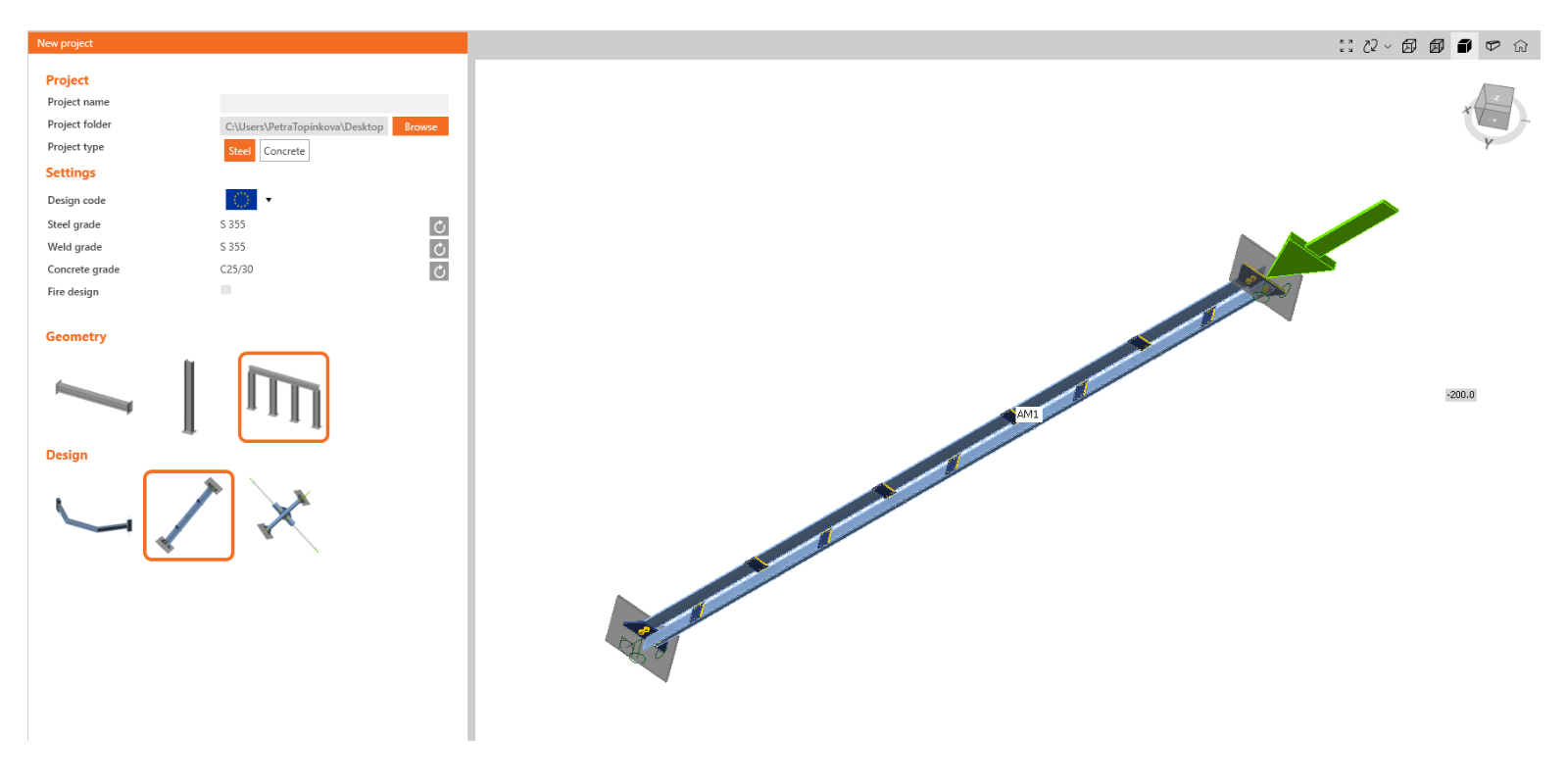
Modeling wizard for typical use-cases in Steel Member
Modeling Wizard
Whether you're unsure of how to properly define elements, boundary conditions, and loads, or you want to create a one-click project, you can use the modeling wizard. Templates exist for the most common use cases. All you need to do is to choose the one that matches your specifications and modify it according to your project's requirements.
The templates are divided into three basic categories based on geometry:
- Beam
- Column
- General
There are then several design options for each category.
Various typical examples are created for a beam, including haunched beams or beams with openings:
For a column, these are mainly isolated elements anchored into the concrete footing with different levels of strengthening:
In the general section, you can find, among other things, examples of bracing diagonals.
As already mentioned, this feature is created based on examples from users as a tool for easier and more efficient work with the application. If you are missing a typical example here, feel free to contact us with your suggestions.
Available in IDEA StatiCa Steel and IDEA StatiCa Complete editions.
Scarica la nuova versione di IDEA StatiCa e prova tutte le funzionalità
Singularity detection in Member
If the model of Member is imperfect in terms of modeling (e.g., a stiffener plate is not welded to the beam or some connection is missing), the singularity message will appear after pushing the Calculate button, and the analysis is stopped.
This was a problem, especially in large Member models where it was difficult to identify which part of the model caused the singularity.
With the new version, the message with the description of the problematic part is shown in the 3D window, and the missing connection can be easily fixed. In case there are more singularities, the first failing part is shown, and after it is fixed, the other is revealed.
Available in IDEA StatiCa Steel.
Download the new version of IDEA StatiCa and try all the features
Design of walls, details, and cross-sections
Ribbon e sistema di navigazione intuitivi per IDEA StatiCa Detail
Lavora con un'interfaccia grafica (GUI) attraente, chiara e semplice da usare per rendere più veloce la progettazione di strutture in calcestruzzo!
Layout dell'applicazione
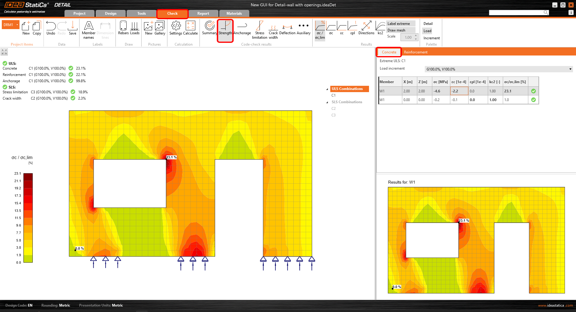
L'interfaccia grafica dell'applicazione Detail è chiara e semplice da usare:
- Sei schede della barra multifunzione: File, Progetto, Strumenti, Verifica, Relazione e Materiali.
- L'attivazione di funzionalità o l'interazione con le finestre di dialogo avviene tramite i pulsanti di comando nei gruppi della barra multifunzione.
- La scena che mostra la struttura in calcestruzzo dell'utente e l'albero di navigazione a sinistra occupa una parte importante di spazio sullo schermo, poiché sono i componenti più importanti per l'utente.
- Le proprietà di un elemento selezionato (le entità possono essere selezionate nell'albero o nella scena) sono presentate nella griglia delle proprietà sul lato destro dell'applicazione.
- La parte inferiore dell'applicazione contiene informazioni di base sulle impostazioni del progetto, come il codice di progettazione, le unità di arrotondamento, le unità di presentazione e un link alla nostra pagina web. Facendo clic su queste entità, si apre la finestra di dialogo con le relative impostazioni, che consente di definire un gruppo selezionato di parametri.
La scheda progetto o il menu laterale (che si apre cliccando sulla scheda File) contengono:
- Comandi di base, come Nuovo, Apri, Salva e molti altri
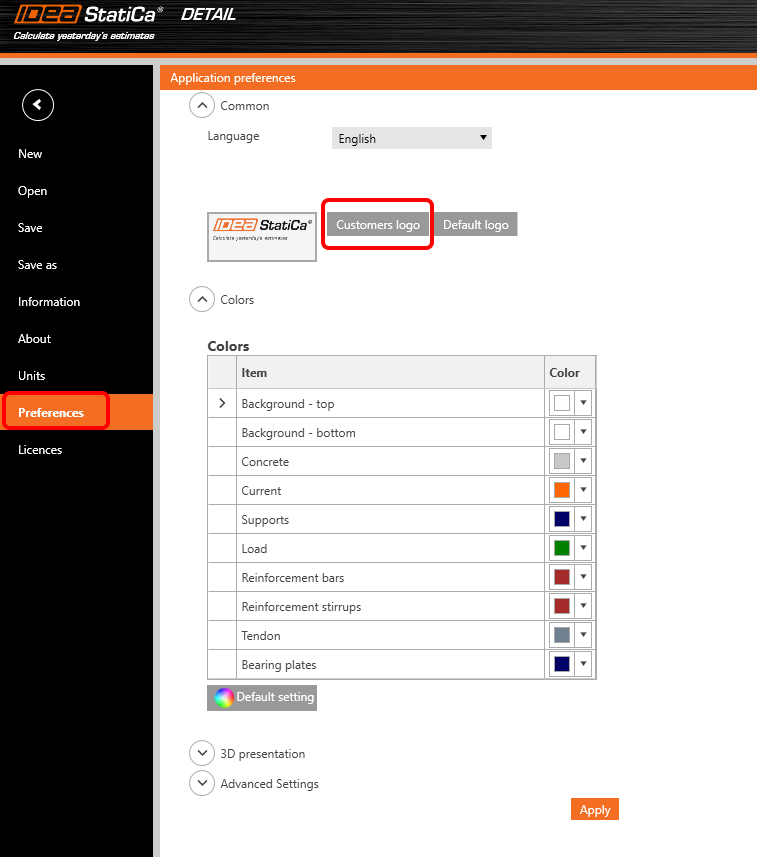
- Le impostazioni dell'applicazione come Unità o Preferenze che possono essere personalizzate dall'utente
Aggiunta di una nuova entità di progetto:
- Ogni progetto può contenere più elementi di progetto
- Un nuovo elemento del progetto viene aggiunto utilizzando i comandi nella barra multifunzione o nel menu laterale (che si apre cliccando sulla scheda File) - sezione Informazioni
- È possibile copiare un elemento esistente quando si lavora su progetti strutturali simili
Come lavorare nell'app Detail
L'interfaccia grafica è molto intuitiva e guida gli utenti su come creare i propri progetti in modo efficiente. Basta seguire passo dopo passo le schede della barra multifunzione.
Nuovo progetto
- Una procedura guidata consente di definire un progetto da un modello (o un tipo di struttura definito dall'utente) e di impostare le proprietà iniziali del materiale
Progetto
- Serve per la progettazione dell'elemento strutturale, compreso il carico e la definizione dell'armatura
- La geometria della struttura e dell'armatura può essere facilmente importata dai file DXF o aggiunta qui tramite appositi pulsanti
- L'albero delle entità contiene tutte le entità definite in un modello. Ogni entità nell'albero ha una serie di comandi accuratamente selezionati nel menu contestuale. Le entità nell'albero possono essere raggruppate in base alla tipologia o come elenco di entità ordinate in sequenza.
- È stata sviluppata una grande funzionalità che aiuta a progettare l'armatura. Disattivando il comando "Disegna armatura" nella barra multifunzione, nella scena viene visualizzata solo l'entità dell'armatura selezionata e il resto viene nascosto. Ciò aiuta con i dettagli di un'armatura selezionata senza interferire con molte altre armature esistenti.
Strumenti
- Per tutti gli ingegneri che hanno difficoltà a progettare la quantità e la disposizione di armatura necessaria, consente metodi di calcolo come l'ottimizzazione della topologia e l'analisi lineare per determinare le aree della struttura che richiedono armatura
- L'albero delle entità è ridotto e contiene solo tutte le armature esistenti
- Anche qui è possibile utilizzare il pulsante "Disegna armatura", la cui funzione è descritta nella sezione Progetto
- Per una visualizzazione ridotta delle armature descritte nella sezione precedente (scheda Progetto), è possibile utilizzare la progettazione semplice dell'armatura anche nella scheda Strumenti
Verifica
- L'albero di navigazione ridotto contiene solo le combinazioni attive per la verifica secondo codice
- Il tipo di verifica viene selezionato facendo clic sul pulsante nella barra multifunzione (gruppo Risultati della verifica normativa)
- I risultati per ciascun tipo di materiale vengono presentati separatamente nella scena. Gli utenti possono selezionare quali risultati presentare selezionando la scheda Calcestruzzo, Armatura o Ancoraggi nella griglia delle proprietà
Relazione
- Sono supportati diversi tipi di relazione di calcolo: una relazione breve e una dettagliata o una distinta dei materiali, se necessario
- Nella relazione dettagliata, gli utenti possono definire arbitrariamente quali risultati e output saranno presentati nel documento finale, il che significa una relazione completamente personalizzabile
- La relazione può essere esportata in un file DOC o PDF
Materiali
- Controlla il diagramma tensione-deformazione di ciascun materiale, calcestruzzo, acciaio dell'armatura o dell'armatura di precompressione
- Se necessario, modificare le proprietà del materiale
Progettare e verificare le strutture in calcestruzzo nella nuova GUI per l'applicazione Detail è semplice e veloce. Come facciamo a saperlo? Perché questa interfaccia utente ha funzionato molto bene per milioni di clienti che utilizzano l'applicazione Connection, che costituisce la base della nuova GUI del Detail.
Scarica la nuova versione di IDEA StatiCa e prova tutte le funzionalità
Interaction code-check advancements in RCS
In the following article, we will explain the approach to the calculation of the longitudinal force caused by shear Ftd,s. This method consists mainly of changing the way the force is applied to the cross-section. We start with the definition of the cross-section subjected by N-My-Mz and then we gradually add the longitudinal force caused by shear and torsion.
Response N-My-Mz
The cross-section is, in the first phase, loaded by a combination of normal force and bending moments N-My-Mz. The results comparison between the software versions provides us with the same results.
If the shear reinforcement is designed in the cross-section, shear can be resisted by a fictitious strut-and-model composed of stirrups, concrete struts, and longitudinal rebars.
Calculated longitudinal force due to shear is applied to the cross-section with all components (concrete and rebars). The initial stress state taken from the N+My+Mz response is already defined for each component.
The equation for the calculation of the longitudinal force due to shear:
\[F_{td,s} = V_{ed}(cot \theta -cot \alpha ) \]
Longitudinal force Ftd,s is, by default, applied to:
- The centroid of the section resisting shear – for the cross-sections where the application is able to define such a section (the red area in the following figure).
- The centroid of the cross-section – for the cross-sections where the application is not able to define such a section.
Interaction N-My-Mz-Vz
The sectional response due to the combination of N+My+Mz+Ftd,s is calculated. We can notice that the stress in concrete and rebars in compression decreased while the stress in tensile reinforcement increased (in comparison with response N+My+Mz). The section is still in equilibrium.
Interaction N-My-Mz-Vz-T
For sections also subjected to torsion, we apply an additional longitudinal tensile force Ftd,t to longitudinal rebars lying inside the stirrup selected for torsion check. The calculation model is slightly different because we assume that the section is composed of longitudinal rebars while neglecting the concrete. The N+My+Mz+Ftd,s response defines each rebar's initial stress state. Consequently, Ftd,t is applied, following the condition of the same strain increment for all rebars resisting torsion.
The assumptions for the calculation mean that in some cases, like sections located above the intermediate support of a continuous beam, different results can be observed. When the stress in tensile reinforcement due to N+My+Mz reached yield stress, other less utilized rebars carried the longitudinal force due to shear (e.g., located in a compression zone).
Available in IDEA StatiCa Concrete and IDEA StatiCa Complete editions.
Scarica la nuova versione di IDEA StatiCa e prova tutte le funzionalità
Importing reinforcements from DXF files in IDEA StatiCa Detail
Reinforcement DXF import improvements in IDEA StatiCa Detail
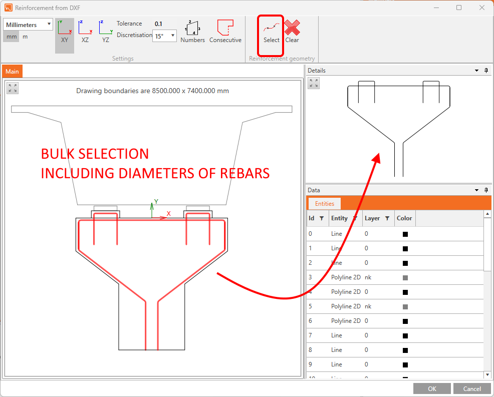
Such functionality has been in the Detail app for a while, and we are constantly improving it according to your needs. Now we are adding the possibility to import all the reinforcement drawn in dxf with respect to its diameter if defined as a global width of a curve. You can import the whole reinforcement layout with various diameters of rebars in one click!
Scarica la nuova versione di IDEA StatiCa e prova tutte le funzionalità
BIM links and education
BIM links reduce modeling time, decrease the number of copy-paste errors, and overcome any issues with data transference. In version 23.1, you can now access our new BIM link with SDS2 by Allplan as well as an IDEA StatiCa plugin for the Rhino Grasshopper tool.
IDEA Grasshopper plugin
About Rhino/Grasshopper
Rhino and Grasshopper is a powerful CAD modeling platform with a large array of plugins available for the architectural and engineering industry. As a parametric modeling tool, Grasshopper has created an extensive and well-maintained ecosystem of third-party plugins, interacting through their powerful geometry engine. Tekla, Revit and all major FEA software have plug-ins for Grasshopper.
How the plugin works
The Grasshopper plugin enables users to interact with IOM and the Connection API using a 'low code' visual programming approach.
Combining Grasshopper with IDEA StatiCa's Open Model and APIs creates an extremely powerful platform for the parametric definition of complex connection geometry plus the automation and optimization of connections.
Linked applications: IDEA Open Model, IDEA StatiCa Connection, IDEA StatiCa Checkbot (Standalone)
The comprehensive description of the IDEA plugin for Grasshopper with 'How to model Examples' is presented on the webpage Rhino to IDEA StatiCa workflow.
Scarica la nuova versione di IDEA StatiCa e prova tutte le funzionalità
BIM link with Allplan SDS2
The Link provides the ability for users to directly transfer fully detailed connections in either a single or bulk selection manner. The user can transfer connection elements such as bolts, welds, stiffeners, and plate cuts modeled in SDS2 detailing tool directly into IDEA StatiCa Checkbot and further into the Connection app.
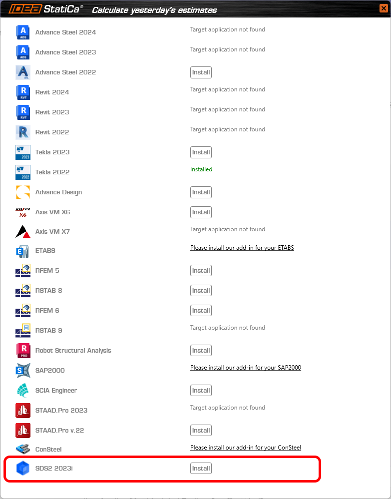
The integration is displayed in the list of fully supported third-party software during the BIM installation process.
A comprehensive description of the IDEA plugin for SDS2 is presented on this webpage.
Scarica la nuova versione di IDEA StatiCa e prova tutte le funzionalità
UX features in parametric design
This makes parameters a usable feature to drive powerful parametric and automated connection modeling.
UX
The UX of the Developer tab has significant features included.
- Parameters and model properties are now split into tabs in the side panel. With Parameters being positioned as the 'primary' element of this functionality.
- It is possible to link parameters to model properties directly from this tab using the add model property link button.
- A Value output column has been included so the user can see the calculated output in real-time.
- A custom Parameter Validation is available to allow template creators to notify others of limitations to their parametric designs.
- The user can select a validation 'type' and choose whether to warn the user or restrict the set to the model.
- If validation is set and passed (=true), a success icon displays.
- If validation is set and not passed (=false), either a warning or error icon displays.
- If no validation is set, no icon displays.
- A unit selection is available to allow users to see the output value in their preferred unit type (set by program settings). Note: all calculations and expression inputs are still to be in basic SI units.
- The Model Property Dialogue works in the following way:
- An Is active column has been added to model properties to show the user if the specific property is visible in the current UI of the program.
- A parameter can now also be edited on a particular added model property.
The IDEA StatiCa development team also looks to take a step further toward parametric templates and the automatic application of standard and simple connections.
Please also see the introduction description in Setting up parametric design with Developer Tab knowledge base article.
Available in IDEA StatiCa Steel and IDEA StatiCa Complete editions.
Download the new version of IDEA StatiCa and try all the features
BimApi solution for AXIS VM 7, Robot Structural Analysis 2024
New BIMapi links
The links to AXIS VM7 and Robot Structural analysis have been available since the patches of 23.0.
This makes it stable, reliable, less prone to create unnecessary errors, and most importantly faster!
When it comes to Robot Structural Analysis we are now able to read eccentricities of 1D elements when importing the model to our Checkbot application. This is a feature that has been loudly asked about by the Robot users. You asked for it, we delivered!
Limitations
Be aware that if you have a project created with BIM link in version 23.0 of IDEA StatiCa and you update to new version of 23.1, you might not be able to read the project due to new BIMapi solution. Therefore, we recommend to finish existing projects with version 23.0.
How to activate the BIM links
Download and install the latest version of IDEA StatiCa. Open IDEA StatiCa and continue to the BIM tab. There, you click Activate your BIM link...
You can find a list of supported FEA/BIM solutions here.
A window pops up asking you "Do you want to allow this app to make changes to your device?" Confirm by selecting Yes.
The BIM links for AXIS VM7 and Robot Structural Analysis 2024 are automatically installed. You can find the status of each BIM link.
Tutorials
You can follow the step-by-step tutorials to learn how to streamline your workflow.
Scarica la nuova versione di IDEA StatiCa e prova tutte le funzionalità
API/Developer documentation website
Where to find it then?
developer.ideastatica.com is the way to go.
This new developer documentation site will give IDEA StatiCa third-party developers and API scripters a single access point for information relating to IDEA StatiCa public services and code.
The site links together static documentation, code documentation, and specific examples for all the personas mentioned in the lead paragraph.
Improvements compared to the previous state
- The public GitHub web page provides a lot of useful information but it may not be that easy to navigate through. Therefore we are going to provide developers with a single access point.
- Breaking change release notes will help to notify developers when and how they need to update their third-party apps.
- Providing a distinction between public WIP developments (should not be used as products) and those that are working products with documentation.
- Wiki provides the ability to create code documentation and tie it to classes and concepts.
- Wiki is automatically updated and maintained.
- Examples are easily accessible from the documentation.
The site is split into 4 distinct sections:
- IDEA Open Model (IOM) - Section relating to the creation and specification of the IOM Data model.
- BIM Links (BIM API) - Section relating to the creation of Checkbot BIM Links using the BIM API framework.
- Design API (API) - Section relating to Design App API's.
- Extensions - Section relating to Extensions created on top of the design app API's.
Download and try features of IDEA StatiCa 23.1
Check the compatibility with your software in the list of supported versions in 23.1
To help you master IDEA StatiCa, we redesigned Campus, which provides you with self-paced e-learning courses, each with the option of obtaining professional-level certification.


