Stiffness analysis of a steel connection (EN)
1 New project
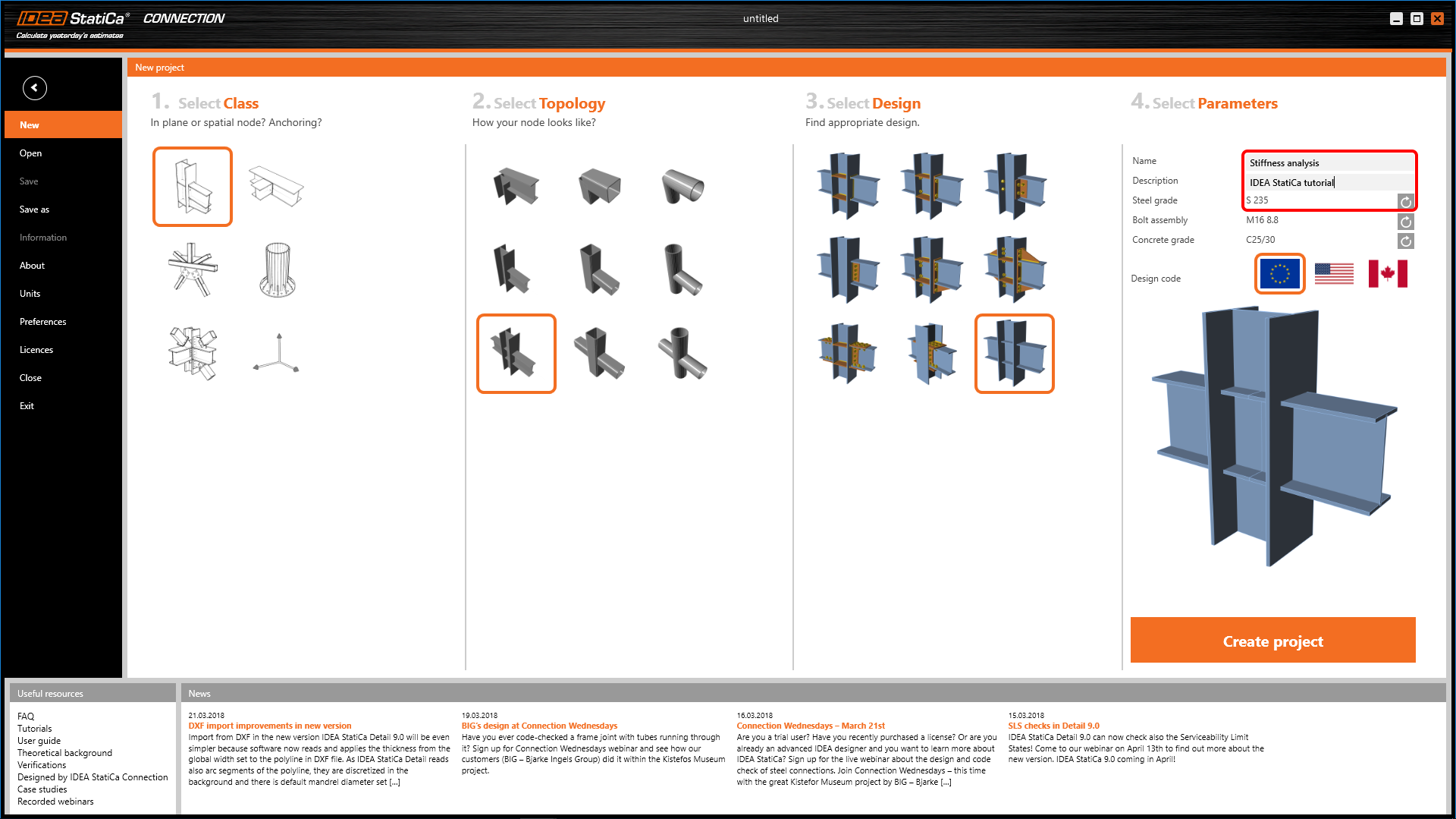
Launch IDEA StatiCa (download the newest version) and select the Connection application.
Create a new project by selecting the starting template closest to the desired design. Fill in the name and choose Eurocode as the design code and the steel grade as S235.
2 Geometry
Three members were automatically created.
3 Load effects
One load effect was automatically generated. Change the values of internal forces in the chart.
4 Design
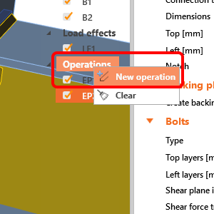
Now define a set of manufacturing operations to model the complete connection. Start with the mouse right-click at the Operations in the tree in the 3D scene. Add a New operation.
In dialog with all available manufacturing operations, choose the End plate operation.
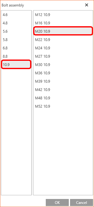
Select the desired bolt grade and size (M20 10.9).
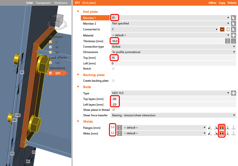
Define the right properties of the created end plate.
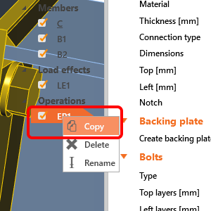
Copy operation EP1: mouse right-click at the EP1 and select Copy.
Change the member related to EP2.
Add the Stiffener operation to the design.
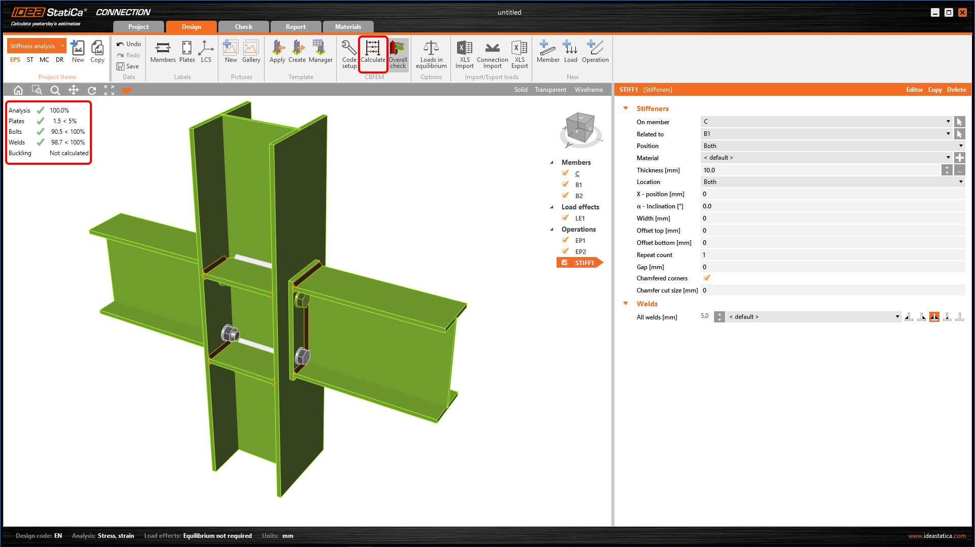
Modify the STIFF1 operation.
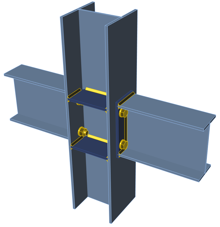
The design is complete.
5 Stress/strain analysis
To have a complete picture of the connection behavior, the stress/strain analysis is run first.
Select Calculate in the ribbon to run the analysis based on the CBFEM method. The numerical model is automatically generated, the calculation is performed, and you can directly see the overall check results in the top-left corner of the scene.
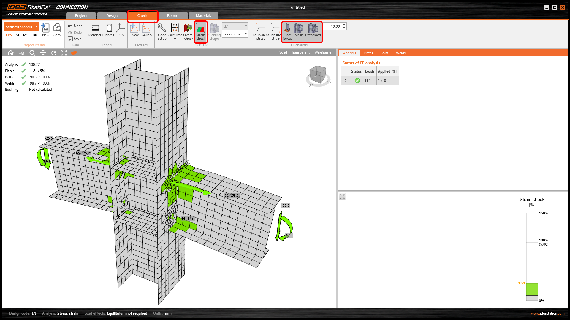
More detailed results can be displayed in the Check tab: activate the Strain check, Bolt forces, Mesh and Deformed shape of the connection in the ribbon to get a full picture of what is happening in the joint.
To keep these results, copy this project item.
6 Stiffness analysis
To keep the stress/strain results, copy this project item.
In the copied project item, change the analysis type to Stiffness (ST) in the top ribbon.
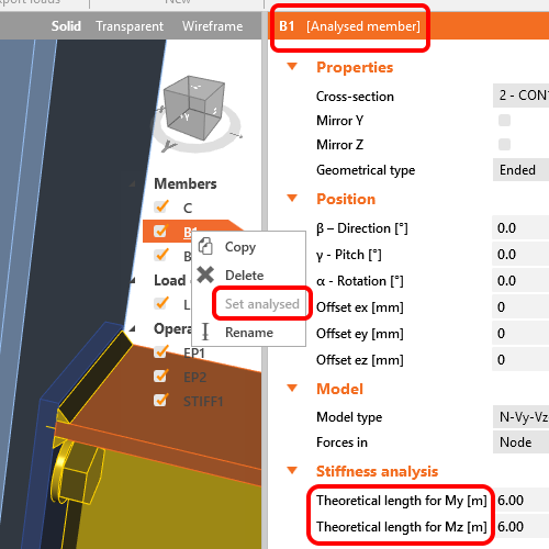
Verify that beam B1 is set as an Analysed member as shown below. (If you want switch Analysed member, you can use right mouse button and set another member as an Analysed member).
The “Theoretical length for My, Mz” can be set for the analyzed member. For more information about the theoretical length, please see Theoretical background and Video – tips for stiffness analysis.
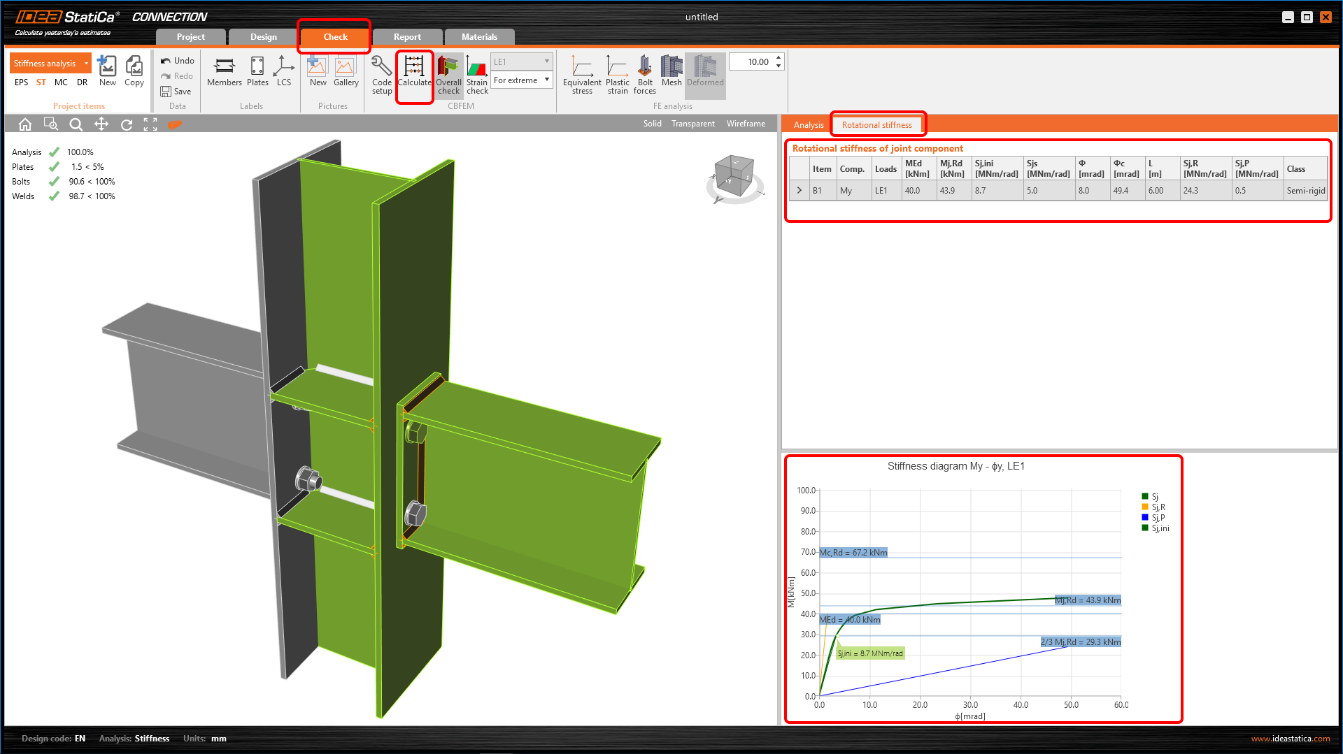
Start the stiffness analysis by the Calculate button in the top ribbon.
The result of the analysis and the load path can be checked in detail in the Rotational stiffness tab. For a better understanding of the results, see the Theoretical Background.
7 Modification of connection
To keep the project CON2, copy it and create CON3.
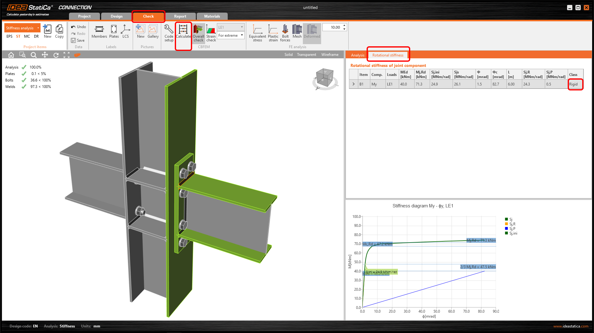
Modify endplate EP1 to increase the rigidity of the connection CON3.
Run the stiffness analysis again. You can notice the change in classification of the connection rigidity from Semi-rigid to Rigid.
For more information on stiffness analysis, please check out our Theoretical background and video.
8 Report
At last, you can review the Report. IDEA StatiCa offers a fully customizable report to print out or save in an editable format.
You have performed a stiffness analysis of a structural steel joint according to Eurocode (EN).
9 More information
Video – introduction to stiffness
Video – tips for stiffness analysis
For more information, please visit our Theoretical background.

