Modeling Grids and Self-weight
Grid for designing new entities
When designing or editing entities in a model that includes a solid block, the grid in the local coordinate system is displayed in the scene, enhancing orientation within the 3D model. This grid is shown for base plates, supports, anchors, surface loads, and result sections.
Users can turn the grid display on or off using the button in the ribbon. The local coordinate system is established through settings in the property grid. The XY plane is defined by the selected surface, while the direction of the X axis is determined by the chosen edge. The grid size is fixed with a step of 0.25 m.
Released in IDEA StatiCa version 24.0.4
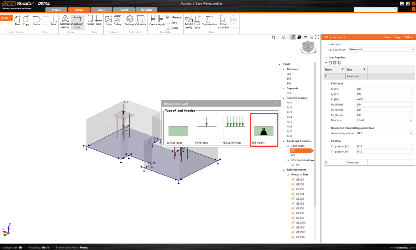
Automatic calculation of self-weight
The Detail app automatically calculates the self-weight of structural elements based on their dimensions and the selected material properties.
Four types of loads can be inserted: Surface Load, Point Load, Group of Forces, and Self-weight.
Other tips and functionality descriptions, not just related to modeling, can be found in the following article: Comprehensive functionality description of 3D Detail
Released in IDEA StatiCa version 24.0.2


